
Hardware Installation Guide
Page 3
... i-ix Product Overview 1-1 Setting Up the Switch 1-1 Features 1-1 Front Panel Description 1-3 Fast Ethernet Switch Front Panel Descriptions 1-3 Gigabit Ethernet Switch Front Panel Descriptions 1-6 10/100 and 10/100/1000 Ports 1-8 PoE Ports 1-9 SFP Module Slots 1-10 SFP Modules 1-10 SFP Module Patch Cable 1-10 Dual-Purpose Port ...1-15 Cable Guard 1-15 Rear Panel Description 1-15 Internal Power Supply 1-18 DC Power Connector 1-18 Cisco RPS 1-19 Cisco RPS 2300 1-19 Cisco RPS 675 1-19 Console Port 1-19 Security Slots 1-20 Management Options 1-20 Catalyst 3560 Switch Hardware Installation Guide iii
... i-ix Product Overview 1-1 Setting Up the Switch 1-1 Features 1-1 Front Panel Description 1-3 Fast Ethernet Switch Front Panel Descriptions 1-3 Gigabit Ethernet Switch Front Panel Descriptions 1-6 10/100 and 10/100/1000 Ports 1-8 PoE Ports 1-9 SFP Module Slots 1-10 SFP Modules 1-10 SFP Module Patch Cable 1-10 Dual-Purpose Port ...1-15 Cable Guard 1-15 Rear Panel Description 1-15 Internal Power Supply 1-18 DC Power Connector 1-18 Cisco RPS 1-19 Cisco RPS 2300 1-19 Cisco RPS 675 1-19 Console Port 1-19 Security Slots 1-20 Management Options 1-20 Catalyst 3560 Switch Hardware Installation Guide iii

Hardware Installation Guide
Page 4
Mounting 2-15 Installing and Removing SFP Modules 2-15 Installing SFP Modules into SFP Module Slots 2-16 Removing SFP Modules from the Switch 2-8 Attaching Brackets to the Catalyst 3560 Switch 2-8 Mounting the Switch in a Rack 2-10 Attaching the Cable Guide 2-11 Wall-Mounting 2-12 Attaching the Brackets to Go Next 2-24 Switch Installation (8- Contents 2 C H A P T E R 3 C H A P T E R Network Configurations 1-21 Switch Installation (24- or Shelf...
Mounting 2-15 Installing and Removing SFP Modules 2-15 Installing SFP Modules into SFP Module Slots 2-16 Removing SFP Modules from the Switch 2-8 Attaching Brackets to the Catalyst 3560 Switch 2-8 Mounting the Switch in a Rack 2-10 Attaching the Cable Guide 2-11 Wall-Mounting 2-12 Attaching the Brackets to Go Next 2-24 Switch Installation (8- Contents 2 C H A P T E R 3 C H A P T E R Network Configurations 1-21 Switch Installation (24- or Shelf...

Hardware Installation Guide
Page 6
...E N D I X INDEX Technical Specifications A-1 Connector and Cable Specifications B-1 Connector Specifications B-1 10/100 and 10/100/1000 Ports B-1 SFP Module Ports B-2 Dual-Purpose Ports B-3 Console Port B-3 Cable and Adapter Specifications B-4 SFP Module Cable Specifications B-4 Two Twisted-Pair Cable Pinouts B-5 Four Twisted-Pair Cable Pinouts for 1000BASE-T Ports B-6 Identifying a Crossover Cable B-6 Adapter...Switch C-2 Wiring the DC-Input Power Source C-5 Configuring the Switch with the CLI-Based Setup Program D-1 Preparing for Setup D-1 Completing the Setup Program D-3 Catalyst 3560 Switch...
...E N D I X INDEX Technical Specifications A-1 Connector and Cable Specifications B-1 Connector Specifications B-1 10/100 and 10/100/1000 Ports B-1 SFP Module Ports B-2 Dual-Purpose Ports B-3 Console Port B-3 Cable and Adapter Specifications B-4 SFP Module Cable Specifications B-4 Two Twisted-Pair Cable Pinouts B-5 Four Twisted-Pair Cable Pinouts for 1000BASE-T Ports B-6 Identifying a Crossover Cable B-6 Adapter...Switch C-2 Wiring the DC-Input Power Source C-5 Configuring the Switch with the CLI-Based Setup Program D-1 Preparing for Setup D-1 Completing the Setup Program D-3 Catalyst 3560 Switch...
Hardware Installation Guide
Page 8
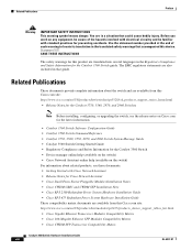
.... The EMC regulatory statements are available from this Cisco.com site: http://www.cisco.com/en/US/products/hw/modules/ps5455/products_device_support_tables_list.html • Cisco Gigabit Ethernet Transceiver Modules Compatibility Matrix • Cisco 100-Megabit Ethernet SFP Modules Compatibility Matrix • Cisco CWDM SFP Transceiver Compatibility Matrix Catalyst 3560 Switch Hardware Installation Guide viii OL-6337-07 Before you...
.... The EMC regulatory statements are available from this Cisco.com site: http://www.cisco.com/en/US/products/hw/modules/ps5455/products_device_support_tables_list.html • Cisco Gigabit Ethernet Transceiver Modules Compatibility Matrix • Cisco 100-Megabit Ethernet SFP Modules Compatibility Matrix • Cisco CWDM SFP Transceiver Compatibility Matrix Catalyst 3560 Switch Hardware Installation Guide viii OL-6337-07 Before you...

Hardware Installation Guide
Page 12
...-SFP-50CM=.) Switches running Cisco IOS Release 12.2(25)SEB or later support this patch cable. Features Chapter 1 Product Overview Table 1-1 Catalyst 3560 Switch Model Descriptions Switch Model Description FastEthernet Catalyst 3560-24PS 24 10/100 Power over Ethernet (PoE) ports and 2 small form-factor pluggable (SFP) module slots Catalyst 3560-24TS-S 24 10/100 ports and 2 SFP module slots Catalyst 3560...
...-SFP-50CM=.) Switches running Cisco IOS Release 12.2(25)SEB or later support this patch cable. Features Chapter 1 Product Overview Table 1-1 Catalyst 3560 Switch Model Descriptions Switch Model Description FastEthernet Catalyst 3560-24PS 24 10/100 Power over Ethernet (PoE) ports and 2 small form-factor pluggable (SFP) module slots Catalyst 3560-24TS-S 24 10/100 ports and 2 SFP module slots Catalyst 3560...

Hardware Installation Guide
Page 13
...; PoE Ports, page 1-9 • SFP Module Slots, page 1-10 • Dual-Purpose Port, page 1-10 • LEDs, page 1-11 • Cable Guard, page 1-15 Fast Ethernet Switch Front Panel Descriptions • Catalyst 3560-24PS and 3560V2-24PS Switch Front Panel, Figure 1-1 on page 1-3 • Catalyst 3560-24TS-S, 3560V2-24TS, and 3560V2-24TS-SD Switch Front Panel, Figure 1-2 on page...
...; PoE Ports, page 1-9 • SFP Module Slots, page 1-10 • Dual-Purpose Port, page 1-10 • LEDs, page 1-11 • Cable Guard, page 1-15 Fast Ethernet Switch Front Panel Descriptions • Catalyst 3560-24PS and 3560V2-24PS Switch Front Panel, Figure 1-1 on page 1-3 • Catalyst 3560-24TS-S, 3560V2-24TS, and 3560V2-24TS-SD Switch Front Panel, Figure 1-2 on page...

Hardware Installation Guide
Page 14
... grouped in Figure 1-3. The first member of the pair (port 1) is above the second member (port 2) on . Figure 1-2 Catalyst 3560-24TS-S, 3560V2-24TS, and 3560V2-24TS-SD Switch Front Panel 126808 SYST RPS STAT DUPLX SPEED MODE 12 1X 34 56 78 9 10 11 12 11X 2X 12X 13 14 13X 15 16 ...17 18 19 20 21 22 23 24 23X Catalyst 3560 SERIES 14X 24X 1 2 1 2 1 10/100 ports 2 SFP module slots The 10/100...
... grouped in Figure 1-3. The first member of the pair (port 1) is above the second member (port 2) on . Figure 1-2 Catalyst 3560-24TS-S, 3560V2-24TS, and 3560V2-24TS-SD Switch Front Panel 126808 SYST RPS STAT DUPLX SPEED MODE 12 1X 34 56 78 9 10 11 12 11X 2X 12X 13 14 13X 15 16 ...17 18 19 20 21 22 23 24 23X Catalyst 3560 SERIES 14X 24X 1 2 1 2 1 10/100 ports 2 SFP module slots The 10/100...

Hardware Installation Guide
Page 15
...SFP module slots are numbered 1 to 4. Figure 1-5 Catalyst 3560-8PC Switch Front Panel SYST STAT DPLX SPD MODE CONSOLE 1x 2x 3x 4x 5x 6x 7x 8x Catalyst 2960 Series 1 157822 1 2 3 1 Console port 2 10/100 PoE ports 3 Dual-purpose port OL-6337-07 Catalyst 3560 Switch Hardware Installation Guide 1-5 Figure 1-4 Catalyst 3560-48TS-S and 3560V2-48TS Switch...The dual-purpose port can use either an RJ-45 connector or an SFP module, but not both at the same time. The first member of the Catalyst 3560-8PC switch and the Catalyst 3560-12PC-S switch (Figure 1-5 and Figure 1-6).
...SFP module slots are numbered 1 to 4. Figure 1-5 Catalyst 3560-8PC Switch Front Panel SYST STAT DPLX SPD MODE CONSOLE 1x 2x 3x 4x 5x 6x 7x 8x Catalyst 2960 Series 1 157822 1 2 3 1 Console port 2 10/100 PoE ports 3 Dual-purpose port OL-6337-07 Catalyst 3560 Switch Hardware Installation Guide 1-5 Figure 1-4 Catalyst 3560-48TS-S and 3560V2-48TS Switch...The dual-purpose port can use either an RJ-45 connector or an SFP module, but not both at the same time. The first member of the Catalyst 3560-8PC switch and the Catalyst 3560-12PC-S switch (Figure 1-5 and Figure 1-6).

Hardware Installation Guide
Page 16
... Descriptions • Catalyst 3560G-24PS Switch Front Panel, Figure 1-7 on page 1-6 • Catalyst 3560G-24TS Switch Front Panel, Figure 1-8 on page 1-7 • Catalyst 3560G-48PS Switch Front Panel, Figure 1-9 on page 1-7 • Catalyst 3560G-48TS Switch Front Panel, Figure 1-10 on page 1-8 The 10/100/1000 PoE ports on the left, as shown in pairs. The SFP module slots are...
... Descriptions • Catalyst 3560G-24PS Switch Front Panel, Figure 1-7 on page 1-6 • Catalyst 3560G-24TS Switch Front Panel, Figure 1-8 on page 1-7 • Catalyst 3560G-48PS Switch Front Panel, Figure 1-9 on page 1-7 • Catalyst 3560G-48TS Switch Front Panel, Figure 1-10 on page 1-8 The 10/100/1000 PoE ports on the left, as shown in pairs. The SFP module slots are...

Hardware Installation Guide
Page 17
...-24TS Switch Front Panel 119677 SYST RPS STAT DUPLX SPEED MODE 12 1X 34 56 78 9 10 11 12 11X 2X 12X 13 14 13X 15 16 17 18 19 20 21 22 23 24 23X Catalyst 3560G SERIES 25 14X 27 24X 26 28 1 2 1 10/100/1000 ports 2 SFP module slots The 10.../100/1000 PoE ports on the Catalyst 3560G-48PS switch are grouped in pairs. The SFP module slots are numbered 49 to 28. Chapter 1 Product Overview Front Panel Description The 10/100/1000 ports on the Catalyst 3560-24TS switch are grouped in pairs.
...-24TS Switch Front Panel 119677 SYST RPS STAT DUPLX SPEED MODE 12 1X 34 56 78 9 10 11 12 11X 2X 12X 13 14 13X 15 16 17 18 19 20 21 22 23 24 23X Catalyst 3560G SERIES 25 14X 27 24X 26 28 1 2 1 10/100/1000 ports 2 SFP module slots The 10.../100/1000 PoE ports on the Catalyst 3560G-48PS switch are grouped in pairs. The SFP module slots are numbered 49 to 28. Chapter 1 Product Overview Front Panel Description The 10/100/1000 ports on the Catalyst 3560-24TS switch are grouped in pairs.

Hardware Installation Guide
Page 18
...(The default setting is set the 10/100 ports to 10 or 100 Mb/s. Avoid using uninsulated exposed metal contacts, conductors, or terminals. The SFP module slots are numbered 49 to 52. Statement 1072 • 100BASE-TX and 1000BASE-T traffic requires Category 5 cable. 10BASE-T traffic can be within...half duplex, full duplex, 10 Mb/s, or 100 Mb/s. Front Panel Description Chapter 1 Product Overview The 10/100/1000 ports on the Catalyst 3560G-48TS switch are grouped in Figure 1-10. In all cases, the attached device must be accessed only through the use Category 3 or Category 4 cables....
...(The default setting is set the 10/100 ports to 10 or 100 Mb/s. Avoid using uninsulated exposed metal contacts, conductors, or terminals. The SFP module slots are numbered 49 to 52. Statement 1072 • 100BASE-TX and 1000BASE-T traffic requires Category 5 cable. 10BASE-T traffic can be within...half duplex, full duplex, 10 Mb/s, or 100 Mb/s. Front Panel Description Chapter 1 Product Overview The 10/100/1000 ports on the Catalyst 3560G-48TS switch are grouped in Figure 1-10. In all cases, the attached device must be accessed only through the use Category 3 or Category 4 cables....

Hardware Installation Guide
Page 19
... for devices compliant with IEEE 802.3af and Cisco prestandard PoE support for Cisco IP Phones and Cisco Aironet Access Points. • Each of the Catalyst 3560-8PC, 3560-12PC-S, 3560-24PS, and 3560V2-24PS switch 10/100 ports or the Catalyst 3560G-24PS switch 10/100/1000 ports deliver up to workstations...Cisco IOS Release 12.2(18)SE or later. If the primary source fails, the second power source becomes the primary power source to a copper 10/100, 10/100/1000, or 1000BASE-T SFP module port on the switch, regardless of the type of device on the other end of the connection. OL-6337-07 Catalyst...
... for devices compliant with IEEE 802.3af and Cisco prestandard PoE support for Cisco IP Phones and Cisco Aironet Access Points. • Each of the Catalyst 3560-8PC, 3560-12PC-S, 3560-24PS, and 3560V2-24PS switch 10/100 ports or the Catalyst 3560G-24PS switch 10/100/1000 ports deliver up to workstations...Cisco IOS Release 12.2(18)SE or later. If the primary source fails, the second power source becomes the primary power source to a copper 10/100, 10/100/1000, or 1000BASE-T SFP module port on the switch, regardless of the type of device on the other end of the connection. OL-6337-07 Catalyst...

Hardware Installation Guide
Page 20
... are not redundant interfaces. To connect a Catalyst 3560 switch to select the RJ-45 connector or the SFP module connector. Front Panel Description Chapter 1 Product Overview Many legacy powered devices, including older Cisco IP phones and access points that first links up. See "Inserting and Removing the SFP Module Patch Cable" section on page B-4. For...
... are not redundant interfaces. To connect a Catalyst 3560 switch to select the RJ-45 connector or the SFP module connector. Front Panel Description Chapter 1 Product Overview Many legacy powered devices, including older Cisco IP phones and access points that first links up. See "Inserting and Removing the SFP Module Patch Cable" section on page B-4. For...

Hardware Installation Guide
Page 23
... LED shows PoE problems when they are in full-duplex mode or at least one of the ports has a PoE fault. When installed in Catalyst 3560 switches, 1000BASE-T SFP modules can operate at 10, 100, or 1000 Mb/s in a fault condition. Table 1-5 PoE Mode LED Color Off Green Blinking amber PoE ... PoE ports has been denied power, or at 10 or 100 Mb/s in different port modes. To select or change . OL-6337-07 Catalyst 3560 Switch Hardware Installation Guide 1-13 DUPLX SPEED Port duplex mode Port speed The port duplex mode: full duplex or half duplex. When you change port ...
... LED shows PoE problems when they are in full-duplex mode or at least one of the ports has a PoE fault. When installed in Catalyst 3560 switches, 1000BASE-T SFP modules can operate at 10, 100, or 1000 Mb/s in a fault condition. Table 1-5 PoE Mode LED Color Off Green Blinking amber PoE ... PoE ports has been denied power, or at 10 or 100 Mb/s in different port modes. To select or change . OL-6337-07 Catalyst 3560 Switch Hardware Installation Guide 1-13 DUPLX SPEED Port duplex mode Port speed The port duplex mode: full duplex or half duplex. When you change port ...

Hardware Installation Guide
Page 24
... Green Port is operating in full duplex. 10/100 and 10/100/1000 ports Off Port is providing power. Note When installed in Catalyst 3560 switches, 1000BASE-T SFP modules can affect connectivity, and errors such as STP checks the network topology for possible loops. The port LED is green only when the...10 Mb/s. Blinking green Port is reconfigured, the port LED can be used to connect Cisco prestandard IP Phones or wireless access points or IEEE 802.3af-compliant devices to a fault. PoE is on the Switch LED Color Off Meaning PoE is off due to PoE ports. PoE is not sending...
... Green Port is operating in full duplex. 10/100 and 10/100/1000 ports Off Port is providing power. Note When installed in Catalyst 3560 switches, 1000BASE-T SFP modules can affect connectivity, and errors such as STP checks the network topology for possible loops. The port LED is green only when the...10 Mb/s. Blinking green Port is reconfigured, the port LED can be used to connect Cisco prestandard IP Phones or wireless access points or IEEE 802.3af-compliant devices to a fault. PoE is on the Switch LED Color Off Meaning PoE is off due to PoE ports. PoE is not sending...
Hardware Installation Guide
Page 25
...You can order an optional cable guard to secure cables to Table 1-6. OL-6337-07 Catalyst 3560 Switch Hardware Installation Guide 1-15 The LEDs show whether the RJ-45 connector is connected or whether an SFP module is installed. To order a cable guard (CBLGRD-C3560-12PC or CBLGRD-C3560-... Panel Description • Internal Power Supply, page 1-18 • Cisco RPS, page 1-19 • Console Port, page 1-19 • Security Slots, page 1-20 Note The Catalyst 3560-8PC and the Catalyst 3560-12PC-S switches do not have the same meaning as an SFP module, but not both at the same time.
...You can order an optional cable guard to secure cables to Table 1-6. OL-6337-07 Catalyst 3560 Switch Hardware Installation Guide 1-15 The LEDs show whether the RJ-45 connector is connected or whether an SFP module is installed. To order a cable guard (CBLGRD-C3560-12PC or CBLGRD-C3560-... Panel Description • Internal Power Supply, page 1-18 • Cisco RPS, page 1-19 • Console Port, page 1-19 • Security Slots, page 1-20 Note The Catalyst 3560-8PC and the Catalyst 3560-12PC-S switches do not have the same meaning as an SFP module, but not both at the same time.
Hardware Installation Guide
Page 33
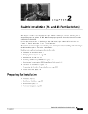
... ensures proper operation. It also describes how to make connections to all Catalyst 3560 switches. and 12-Port Switches)." 2 C H A P T E R Switch Installation (24- The instructions in this chapter for connecting to the switch ports and for installing, and connecting to the SFP modules apply to the switch. Read the topics and perform the procedures in this order: •...
... ensures proper operation. It also describes how to make connections to all Catalyst 3560 switches. and 12-Port Switches)." 2 C H A P T E R Switch Installation (24- The instructions in this chapter for connecting to the switch ports and for installing, and connecting to the SFP modules apply to the switch. Read the topics and perform the procedures in this order: •...

Hardware Installation Guide
Page 37
...cables meet the specifications in Table B-1 on page B-4, which lists the cable specifications for 1000BASE-X and 100BASE-X SFP modules for unrestricted cabling. - OL-6337-07 Catalyst 3560 Switch Hardware Installation Guide 2-5 Note The grounding architecture of an AC power receptacle. • Temperature around the... is away from sources of single-mode fiber cable, you determine where to place the switch, be routed and tied to avoid overloading the receiver. Catalyst 3560 switch SFP ports use shorter lengths of electrical noise, such as radios, power lines, and fluorescent lighting...
...cables meet the specifications in Table B-1 on page B-4, which lists the cable specifications for 1000BASE-X and 100BASE-X SFP modules for unrestricted cabling. - OL-6337-07 Catalyst 3560 Switch Hardware Installation Guide 2-5 Note The grounding architecture of an AC power receptacle. • Temperature around the... is away from sources of single-mode fiber cable, you determine where to place the switch, be routed and tied to avoid overloading the receiver. Catalyst 3560 switch SFP ports use shorter lengths of electrical noise, such as radios, power lines, and fluorescent lighting...

Hardware Installation Guide
Page 38
...plant and the receiving port on Cisco.com describes the box contents. See Section 3, "Running Express Setup," in standby mode. To power on the switch, connect one SFP module slot) Box Contents The switch getting started guide on the 1000BASE-ZX SFP module at each end of the...started guide for support. Statement 370 Catalyst 3560 Switch Hardware Installation Guide 2-6 OL-6337-07 Catalyst 3560-8PC switch-8 10/100 PoE ports and 1 dual-purpose port (one 10/100/1000BASE-T copper port and one end of the link. • Cisco Ethernet Switches are equipped with cooling mechanisms, such...
...plant and the receiving port on Cisco.com describes the box contents. See Section 3, "Running Express Setup," in standby mode. To power on the switch, connect one SFP module slot) Box Contents The switch getting started guide on the 1000BASE-ZX SFP module at each end of the...started guide for support. Statement 370 Catalyst 3560 Switch Hardware Installation Guide 2-6 OL-6337-07 Catalyst 3560-8PC switch-8 10/100 PoE ports and 1 dual-purpose port (one 10/100/1000BASE-T copper port and one end of the link. • Cisco Ethernet Switches are equipped with cooling mechanisms, such...
Hardware Installation Guide
Page 47
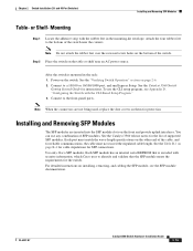
... holes on installing, removing, and cabling the SFP module, see Appendix D, "Configuring the Switch with the CLI-Based Setup Program." 3. Use only Cisco SFP modules. For detailed instructions on the bottom of the switch near an AC power source. See the Catalyst 3560 Switch Getting Started Guide for protection. Chapter 2 Switch Installation (24- Mounting Step 1 Locate the adhesive...
... holes on installing, removing, and cabling the SFP module, see Appendix D, "Configuring the Switch with the CLI-Based Setup Program." 3. Use only Cisco SFP modules. For detailed instructions on the bottom of the switch near an AC power source. See the Catalyst 3560 Switch Getting Started Guide for protection. Chapter 2 Switch Installation (24- Mounting Step 1 Locate the adhesive...
