
Hardware Installation Guide
Page 13
... 15 16 17 18 19 20 21 22 23 24 Catalyst 3560 SERIES PoE-24 23X 14X 24X 1 2 1 2 1 10/100 PoE ports 2 SFP module slots Catalyst 3560 Switch Hardware Installation Guide 1-3 The SFP module slots are autonegotiated....Catalyst 3560-24TS-S, 3560V2-24TS, and 3560V2-24TS-SD Switch Front Panel, Figure 1-2 on page 1-4 • Catalyst 3560-48PS and 3560V2-48PS Switch Front Panel, Figure 1-3 on page 1-4 • Catalyst 3560-48TS-S and 3560V2-48TS Switch Front Panel, Figure 1-4 on page 1-5 • Catalyst 3560-8PC Switch Front Panel, Figure 1-5 on page 1-5 • Catalyst 3560-12PC-S Switch...
... 15 16 17 18 19 20 21 22 23 24 Catalyst 3560 SERIES PoE-24 23X 14X 24X 1 2 1 2 1 10/100 PoE ports 2 SFP module slots Catalyst 3560 Switch Hardware Installation Guide 1-3 The SFP module slots are autonegotiated....Catalyst 3560-24TS-S, 3560V2-24TS, and 3560V2-24TS-SD Switch Front Panel, Figure 1-2 on page 1-4 • Catalyst 3560-48PS and 3560V2-48PS Switch Front Panel, Figure 1-3 on page 1-4 • Catalyst 3560-48TS-S and 3560V2-48TS Switch Front Panel, Figure 1-4 on page 1-5 • Catalyst 3560-8PC Switch Front Panel, Figure 1-5 on page 1-5 • Catalyst 3560-12PC-S Switch...

Hardware Installation Guide
Page 14
...slots are numbered 1 to 4. Front Panel Description Chapter 1 Product Overview The 10/100 ports on the switch are grouped in Figure 1-2. Figure 1-2 Catalyst 3560-24TS-S, 3560V2-24TS, and 3560V2-24TS-SD Switch Front Panel 126808 SYST RPS STAT DUPLX SPEED MODE 12 1X 34 56 78 9 10 11 12 11X ...2X 12X 13 14 13X 15 16 17 18 19 20 21 22 23 24 23X Catalyst 3560 SERIES 14X 24X 1 2 1 2...
...slots are numbered 1 to 4. Front Panel Description Chapter 1 Product Overview The 10/100 ports on the switch are grouped in Figure 1-2. Figure 1-2 Catalyst 3560-24TS-S, 3560V2-24TS, and 3560V2-24TS-SD Switch Front Panel 126808 SYST RPS STAT DUPLX SPEED MODE 12 1X 34 56 78 9 10 11 12 11X ...2X 12X 13 14 13X 15 16 17 18 19 20 21 22 23 24 23X Catalyst 3560 SERIES 14X 24X 1 2 1 2...

Hardware Installation Guide
Page 15
... 31 32 16X 18X 33 31X 33X 34 35 36 37 38 39 40 41 42 43 44 45 46 47 48 47X 32X 34X Catalyst 3560 SERIES 1 3 48X 2 4 1 2 1 10/100 ports 2 SFP module slots The console port, 10/100 PoE ports, and a dual-purpose port are numbered 1 to 4. The SFP module... use either an RJ-45 connector or an SFP module, but not both at the same time. Figure 1-5 Catalyst 3560-8PC Switch Front Panel SYST STAT DPLX SPD MODE CONSOLE 1x 2x 3x 4x 5x 6x 7x 8x Catalyst 2960 Series 1 157822 1 2 3 1 Console port 2 10/100 PoE ports 3 Dual-purpose port OL-6337-07...
... 31 32 16X 18X 33 31X 33X 34 35 36 37 38 39 40 41 42 43 44 45 46 47 48 47X 32X 34X Catalyst 3560 SERIES 1 3 48X 2 4 1 2 1 10/100 ports 2 SFP module slots The console port, 10/100 PoE ports, and a dual-purpose port are numbered 1 to 4. The SFP module... use either an RJ-45 connector or an SFP module, but not both at the same time. Figure 1-5 Catalyst 3560-8PC Switch Front Panel SYST STAT DPLX SPD MODE CONSOLE 1x 2x 3x 4x 5x 6x 7x 8x Catalyst 2960 Series 1 157822 1 2 3 1 Console port 2 10/100 PoE ports 3 Dual-purpose port OL-6337-07...

Hardware Installation Guide
Page 16
... 14 13X 15 16 17 18 19 20 21 22 23 24 Catalyst 3560G SERIES PoE-24 23X 25 14X 27 24X 26 28 1 2 1 10/100/1000 ports 2 SFP module slots Catalyst 3560 Switch Hardware Installation Guide 1-6 OL-6337-07 The SFP module slots are... ports 3 Dual-purpose port Gigabit Ethernet Switch Front Panel Descriptions • Catalyst 3560G-24PS Switch Front Panel, Figure 1-7 on page 1-6 • Catalyst 3560G-24TS Switch Front Panel, Figure 1-8 on page 1-7 • Catalyst 3560G-48PS Switch Front Panel, Figure 1-9 on page 1-7 • Catalyst 3560G-48TS Switch Front Panel, Figure 1-10 on page ...
... 14 13X 15 16 17 18 19 20 21 22 23 24 Catalyst 3560G SERIES PoE-24 23X 25 14X 27 24X 26 28 1 2 1 10/100/1000 ports 2 SFP module slots Catalyst 3560 Switch Hardware Installation Guide 1-6 OL-6337-07 The SFP module slots are... ports 3 Dual-purpose port Gigabit Ethernet Switch Front Panel Descriptions • Catalyst 3560G-24PS Switch Front Panel, Figure 1-7 on page 1-6 • Catalyst 3560G-24TS Switch Front Panel, Figure 1-8 on page 1-7 • Catalyst 3560G-48PS Switch Front Panel, Figure 1-9 on page 1-7 • Catalyst 3560G-48TS Switch Front Panel, Figure 1-10 on page ...

Hardware Installation Guide
Page 17
...14 13X 15 16 17 18 19 20 21 22 23 24 23X Catalyst 3560G SERIES 25 14X 27 24X 26 28 1 2 1 10/100/1000 ports 2 SFP module slots The 10/100/1000 PoE ports on the Catalyst 3560-24TS switch are grouped in pairs. Chapter 1 Product Overview Front Panel Description The 10.../100/1000 ports on the Catalyst 3560G-48PS switch are grouped in pairs. The first ...
...14 13X 15 16 17 18 19 20 21 22 23 24 23X Catalyst 3560G SERIES 25 14X 27 24X 26 28 1 2 1 10/100/1000 ports 2 SFP module slots The 10/100/1000 PoE ports on the Catalyst 3560-24TS switch are grouped in pairs. Chapter 1 Product Overview Front Panel Description The 10.../100/1000 ports on the Catalyst 3560G-48PS switch are grouped in pairs. The first ...

Hardware Installation Guide
Page 18
... 31 32 16X 18X 33 31X 33X 34 35 36 37 38 39 40 41 42 43 44 45 46 47 48 47X 32X 34X Catalyst 3560G SERIES 49 51 48X 50 52 1 2 1 10/100/1000 ports 2 SFP module slots 10/100 and 10/100/1000 Ports • You can use of... restricted access location are numbered 49 to 10 or 100 Mb/s. Front Panel Description Chapter 1 Product Overview The 10/100/1000 ports on the Catalyst 3560G-48TS switch are made aware of the hazard. Port 3 is 1000 Mb/s. • When set the 10/100 ports to half, full, or autonegotiate on Gigabit...
... 31 32 16X 18X 33 31X 33X 34 35 36 37 38 39 40 41 42 43 44 45 46 47 48 47X 32X 34X Catalyst 3560G SERIES 49 51 48X 50 52 1 2 1 10/100/1000 ports 2 SFP module slots 10/100 and 10/100/1000 Ports • You can use of... restricted access location are numbered 49 to 10 or 100 Mb/s. Front Panel Description Chapter 1 Product Overview The 10/100/1000 ports on the Catalyst 3560G-48TS switch are made aware of the hazard. Port 3 is 1000 Mb/s. • When set the 10/100 ports to half, full, or autonegotiate on Gigabit...

Hardware Installation Guide
Page 20
... Description Chapter 1 Product Overview Many legacy powered devices, including older Cisco IP phones and access points that first links up. Use fiber-optic cables with RJ-45 connectors to connect to the switches by a crossover cable. For information about configuring speed and duplex ..., passive cable with dual front ends-an RJ-45 connector and an SFP module connector. To connect a Catalyst 3560 switch to other Catalyst series switches, you can connect only two Catalyst 3560 switches. One shows the status of the RJ-45 port, and one connector of the SFP module port. Dual...
... Description Chapter 1 Product Overview Many legacy powered devices, including older Cisco IP phones and access points that first links up. Use fiber-optic cables with RJ-45 connectors to connect to the switches by a crossover cable. For information about configuring speed and duplex ..., passive cable with dual front ends-an RJ-45 connector and an SFP module connector. To connect a Catalyst 3560 switch to other Catalyst series switches, you can connect only two Catalyst 3560 switches. One shows the status of the RJ-45 port, and one connector of the SFP module port. Dual...
Hardware Installation Guide
Page 39
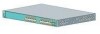
... and then reflect the switch operating status. If a switch fails POST, the System LED turns amber. Call Cisco technical support representative if your safety: • This unit should be mounted at the bottom of the rack if it begins the POST, a series of the rack. &#...can blink during the test. Powering Off the Switch After a successful POST, disconnect the power cord from the switch. and 48-Port Switches) Installing the Switch As the switch powers on page 2-7. POST failures are provided to the Catalyst 3560 Switch, page 2-8 • Mounting the Switch in a Rack, page 2-10 • ...
... and then reflect the switch operating status. If a switch fails POST, the System LED turns amber. Call Cisco technical support representative if your safety: • This unit should be mounted at the bottom of the rack if it begins the POST, a series of the rack. &#...can blink during the test. Powering Off the Switch After a successful POST, disconnect the power cord from the switch. and 48-Port Switches) Installing the Switch As the switch powers on page 2-7. POST failures are provided to the Catalyst 3560 Switch, page 2-8 • Mounting the Switch in a Rack, page 2-10 • ...

Hardware Installation Guide
Page 40
... side of the switch. and 48-Port Switches) Removing Screws from the Switch Before you install the switch in a rack, remove the switch chassis screws (see Figure 2-1.) Figure 2-1 Removing Screws from the Catalyst 3560 Switch 97916 40 41 42 43 44 45 46 47 48 47X Catalyst 3560 SERIES PoE-48 1 3 48X 2 4 Attaching Brackets to a Catalyst 3560 Switch, Front Panel Forward...
... side of the switch. and 48-Port Switches) Removing Screws from the Switch Before you install the switch in a rack, remove the switch chassis screws (see Figure 2-1.) Figure 2-1 Removing Screws from the Catalyst 3560 Switch 97916 40 41 42 43 44 45 46 47 48 47X Catalyst 3560 SERIES PoE-48 1 3 48X 2 4 Attaching Brackets to a Catalyst 3560 Switch, Front Panel Forward...
Hardware Installation Guide
Page 42
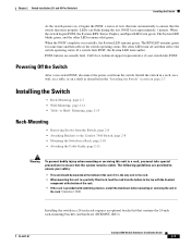
... Catalyst 3560 Switch in Figure 2-8. Installing the Switch Chapter 2 Switch Installation (24- and 48-Port Switches) Figure 2-6 Attaching Brackets for 19-Inch Telco Racks to a Catalyst 3560 Switch 97921 40 41 42 43 44 45 46 47 48 47X Catalyst 3560 SERIES PoE-48 1 3 48X 2 4 1 1 Phillips flat-head screws Figure 2-7 Attaching Brackets for 24-Inch Telco Racks to a Catalyst 3560 Switch...
... Catalyst 3560 Switch in Figure 2-8. Installing the Switch Chapter 2 Switch Installation (24- and 48-Port Switches) Figure 2-6 Attaching Brackets for 19-Inch Telco Racks to a Catalyst 3560 Switch 97921 40 41 42 43 44 45 46 47 48 47X Catalyst 3560 SERIES PoE-48 1 3 48X 2 4 1 1 Phillips flat-head screws Figure 2-7 Attaching Brackets for 24-Inch Telco Racks to a Catalyst 3560 Switch...
Hardware Installation Guide
Page 43
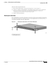
... 18X 33 31X 33X 34 35 36 37 38 39 40 41 42 43 44 45 46 47 48 Catalyst 3560 SERIES PoE-48 47X 32X 34X 1 3 48X 2 4 1 Cable guide screw 97924 OL-6337-07 Catalyst 3560 Switch Hardware Installation Guide 2-11 Use the supplied black screw shown in the rack. Power on the...
... 18X 33 31X 33X 34 35 36 37 38 39 40 41 42 43 44 45 46 47 48 Catalyst 3560 SERIES PoE-48 47X 32X 34X 1 3 48X 2 4 1 Cable guide screw 97924 OL-6337-07 Catalyst 3560 Switch Hardware Installation Guide 2-11 Use the supplied black screw shown in the rack. Power on the...
Hardware Installation Guide
Page 44
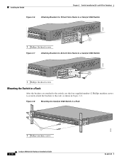
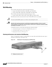
...48 47X Catalyst 3560 SERIES PoE-48 1 3 48X 2 4 1 1 Phillips truss-head screws 2-12 Catalyst 3560 Switch Hardware Installation Guide OL-6337-07 Statement 378 To install the switch on a wall, follow the correct procedures could result in this section show the Catalyst 3560G-48PS switch as an ... wall-mounting the switch. and 48-Port Switches) Wall-Mounting These switches wall-mount only with the front panel facing up: • Catalyst 3560-24PS, 3560-24TS-S, 3560-48PS, and 3560-48TS-S • Catalyst 3560G-24PS, 3560G-24TS, 3560G-48PS, and 3560G-48TS These switches wall-mount with...
...48 47X Catalyst 3560 SERIES PoE-48 1 3 48X 2 4 1 1 Phillips truss-head screws 2-12 Catalyst 3560 Switch Hardware Installation Guide OL-6337-07 Statement 378 To install the switch on a wall, follow the correct procedures could result in this section show the Catalyst 3560G-48PS switch as an ... wall-mounting the switch. and 48-Port Switches) Wall-Mounting These switches wall-mount only with the front panel facing up: • Catalyst 3560-24PS, 3560-24TS-S, 3560-48PS, and 3560-48TS-S • Catalyst 3560G-24PS, 3560G-24TS, 3560G-48PS, and 3560G-48TS These switches wall-mount with...
Hardware Installation Guide
Page 46
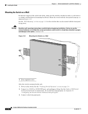
... shown in the rack: 1. Warning Read the wall-mounting instructions carefully before beginning installation. See the "Verifying Switch Operation" section on the switch. Power on page 2-6. 2. Installing the Switch Chapter 2 Switch Installation (24- See the "Wall-Mounting" section on a Wall Catalyst 3750 SERIES 2X 13X 14X 2X 2X MODE STASCPKEDEUDPSLTXAMTASRTPRSSYST 97927 1 1 1 User-supplied screws After the...
... shown in the rack: 1. Warning Read the wall-mounting instructions carefully before beginning installation. See the "Verifying Switch Operation" section on the switch. Power on page 2-6. 2. Installing the Switch Chapter 2 Switch Installation (24- See the "Wall-Mounting" section on a Wall Catalyst 3750 SERIES 2X 13X 14X 2X 2X MODE STASCPKEDEUDPSLTXAMTASRTPRSSYST 97927 1 1 1 User-supplied screws After the...
Hardware Installation Guide
Page 48
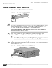
... 2-14.) Figure 2-14 Installing an SFP Module into an SFP Module Slot 40 41 42 43 44 45 46 47 48 47X Catalyst 3560 SERIES PoE-48 1 3 48X 2 4 97928 2-16 Catalyst 3560 Switch Hardware Installation Guide OL-6337-07 Note On some SFP modules, the send and receive (TX and RX) markings might be...
... 2-14.) Figure 2-14 Installing an SFP Module into an SFP Module Slot 40 41 42 43 44 45 46 47 48 47X Catalyst 3560 SERIES PoE-48 1 3 48X 2 4 97928 2-16 Catalyst 3560 Switch Hardware Installation Guide OL-6337-07 Note On some SFP modules, the send and receive (TX and RX) markings might be...

Hardware Installation Guide
Page 49
... a Bale-Clasp Latch SFP Module by Using a Flat-Blade Screwdriver 97929 40 41 42 43 44 45 46 47 48 47X Catalyst 3560 SERIES PoE-48 1 3 1 Bale clasp 48X 2 4 1 Step 4 Grasp the SFP module between your thumb and index finger,... and carefully remove it , carefully use a small, flat-blade screwdriver or other long, narrow instrument to use a twisted four-pair, Category 5 cable. OL-6337-07 Catalyst 3560 Switch Hardware Installation Guide 2-17 and 48-Port Switches...
... a Bale-Clasp Latch SFP Module by Using a Flat-Blade Screwdriver 97929 40 41 42 43 44 45 46 47 48 47X Catalyst 3560 SERIES PoE-48 1 3 1 Bale clasp 48X 2 4 1 Step 4 Grasp the SFP module between your thumb and index finger,... and carefully remove it , carefully use a small, flat-blade screwdriver or other long, narrow instrument to use a twisted four-pair, Category 5 cable. OL-6337-07 Catalyst 3560 Switch Hardware Installation Guide 2-17 and 48-Port Switches...
Hardware Installation Guide
Page 50
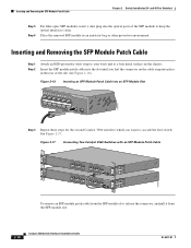
... 13X 15 16 17 18 19 20 21 22 23 24 23X Catalyst 3560 SERIES 14X 24X 1 2 126811 To remove an SFP module patch cable from the SFP module slot, release the connector, and pull it from the SFP module slot. 2-18 Catalyst 3560 Switch Hardware Installation Guide OL-6337-07 and 48-Port... metal surface on the cable snap into an SFP Module Slot 13 14 13X 15 16 17 18 19 20 21 22 23 24 23X Catalyst 3560 SERIES 14X 24X 1 2 126810 Step 3 Repeat these steps for the second Catalyst 3560 switch to which you feel the connector on the chassis. See Figure 2-17.
... 13X 15 16 17 18 19 20 21 22 23 24 23X Catalyst 3560 SERIES 14X 24X 1 2 126811 To remove an SFP module patch cable from the SFP module slot, release the connector, and pull it from the SFP module slot. 2-18 Catalyst 3560 Switch Hardware Installation Guide OL-6337-07 and 48-Port... metal surface on the cable snap into an SFP Module Slot 13 14 13X 15 16 17 18 19 20 21 22 23 24 23X Catalyst 3560 SERIES 14X 24X 1 2 126810 Step 3 Repeat these steps for the second Catalyst 3560 switch to which you feel the connector on the chassis. See Figure 2-17.
Hardware Installation Guide
Page 53
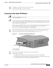
...LED turns green. This process takes about the LC on the SFP module. and 48-Port Switches) Connecting the Switch to a Fiber-Optic SFP Module Port 40 41 42 43 44 45 46 47 48 47X Catalyst 3560 SERIES PoE-48 1 3 48X 2 4 1 97931 1 LC connector Step 3 Step 4 ... and reboot the connected device, if necessary. Step 4 Repeat Steps 1 through 3 to Fiber-Optic SFP Modules Warning Class 1 laser product. Chapter 2 Switch Installation (24- Step 2 Insert one end of the fiber-optic cable into a fiber-optic connector on page 2-5. See Appendix B, "Connector and Cable Specifications...
...LED turns green. This process takes about the LC on the SFP module. and 48-Port Switches) Connecting the Switch to a Fiber-Optic SFP Module Port 40 41 42 43 44 45 46 47 48 47X Catalyst 3560 SERIES PoE-48 1 3 48X 2 4 1 97931 1 LC connector Step 3 Step 4 ... and reboot the connected device, if necessary. Step 4 Repeat Steps 1 through 3 to Fiber-Optic SFP Modules Warning Class 1 laser product. Chapter 2 Switch Installation (24- Step 2 Insert one end of the fiber-optic cable into a fiber-optic connector on page 2-5. See Appendix B, "Connector and Cable Specifications...
Hardware Installation Guide
Page 54
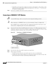
... takes about 30 seconds, and then the port LED turns green. 2-22 Catalyst 3560 Switch Hardware Installation Guide OL-6337-07 Figure 2-20 Connecting to a 1000BASE-T SFP Module 97932 40 41 42 43 44 45 46 47 48 47X Catalyst 3560 SERIES PoE-48 1 3 1 1 RJ-45 connector 48X 2 4 Step 2 Step... 3 Insert the other cable end in the RJ-45 connector. When connecting to cabling problems. If necessary, reconfigure and restart the switch or target device.
... takes about 30 seconds, and then the port LED turns green. 2-22 Catalyst 3560 Switch Hardware Installation Guide OL-6337-07 Figure 2-20 Connecting to a 1000BASE-T SFP Module 97932 40 41 42 43 44 45 46 47 48 47X Catalyst 3560 SERIES PoE-48 1 3 1 1 RJ-45 connector 48X 2 4 Step 2 Step... 3 Insert the other cable end in the RJ-45 connector. When connecting to cabling problems. If necessary, reconfigure and restart the switch or target device.

Hardware Installation Guide
Page 55
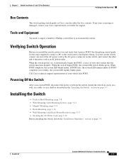
If both ports are connected, the SFP module port has priority. OL-6337-07 Catalyst 3560 Switch Hardware Installation Guide 2-23 Figure 2-21 Connecting to a Dual-Purpose Port 5x 6x 7x 8x 1 2 Catalyst 3560 SERIES PoE-8 1 210093 1 RJ-45 connector 2 LC connector Step 2 Only one port can change this ... device might not be turned on, there might be a cable problem, or there might be active at a time. and 48-Port Switches) Connecting the Switch to Compatible Devices Step 4 • If the LED is connected to the SFP module port, as shown in the target device. You...
If both ports are connected, the SFP module port has priority. OL-6337-07 Catalyst 3560 Switch Hardware Installation Guide 2-23 Figure 2-21 Connecting to a Dual-Purpose Port 5x 6x 7x 8x 1 2 Catalyst 3560 SERIES PoE-8 1 210093 1 RJ-45 connector 2 LC connector Step 2 Only one port can change this ... device might not be turned on, there might be a cable problem, or there might be active at a time. and 48-Port Switches) Connecting the Switch to Compatible Devices Step 4 • If the LED is connected to the SFP module port, as shown in the target device. You...
Hardware Installation Guide
Page 63
... representative if your Cisco representative or reseller for the steps required to connect a PC to the switch and to rack-mount the switch. See the getting started guide for support. When the switch powers on the switch, and connect the other end of tests that verifies that it automatically begins the POST, a series of the power...
... representative if your Cisco representative or reseller for the steps required to connect a PC to the switch and to rack-mount the switch. See the getting started guide for support. When the switch powers on the switch, and connect the other end of tests that verifies that it automatically begins the POST, a series of the power...

