
Hardware Installation Guide
Page 4
...the Switch on a Wall 2-14 Table- Contents 2 C H A P T E R 3 C H A P T E R Network Configurations 1-21 Switch Installation (24- and 48-Port Switches) 2-1 Preparing for Installation 2-1 Warnings 2-2 Installation Guidelines 2-5 Box Contents 2-6 Tools and Equipment 2-6 Verifying Switch Operation 2-6 Powering Off the Switch 2-7 Installing the Switch ... Connecting to a Dual-Purpose Port 2-23 Where to the Switch for Installation 3-1 Warnings 3-2 Installation Guidelines 3-5 Equipment That You Supply 3-6 Catalyst 3560 Switch Hardware Installation Guide iv OL-6337-07 Mounting 2-15 Installing ...
...the Switch on a Wall 2-14 Table- Contents 2 C H A P T E R 3 C H A P T E R Network Configurations 1-21 Switch Installation (24- and 48-Port Switches) 2-1 Preparing for Installation 2-1 Warnings 2-2 Installation Guidelines 2-5 Box Contents 2-6 Tools and Equipment 2-6 Verifying Switch Operation 2-6 Powering Off the Switch 2-7 Installing the Switch ... Connecting to a Dual-Purpose Port 2-23 Where to the Switch for Installation 3-1 Warnings 3-2 Installation Guidelines 3-5 Equipment That You Supply 3-6 Catalyst 3560 Switch Hardware Installation Guide iv OL-6337-07 Mounting 2-15 Installing ...

Hardware Installation Guide
Page 11
... devices like workstations, Cisco Wireless Access Points, Cisco IP Phones, and other network devices such as servers, routers, and other network devices. Features The 24- These topics are hot-swappable. OL-6337-07 Catalyst 3560 Switch Hardware Installation Guide 1-1 Product Overview 1 C H A P T E R The Catalyst 3560 switch-also referred to as the switch-is an Ethernet switch to which you might...
... devices like workstations, Cisco Wireless Access Points, Cisco IP Phones, and other network devices such as servers, routers, and other network devices. Features The 24- These topics are hot-swappable. OL-6337-07 Catalyst 3560 Switch Hardware Installation Guide 1-1 Product Overview 1 C H A P T E R The Catalyst 3560 switch-also referred to as the switch-is an Ethernet switch to which you might...

Hardware Installation Guide
Page 12
...-T (only Catalyst 3560 24- and 12-port switches) • 100BASE-FX • 100BASE-LX (only Catalyst 3560 8- Catalyst 3560 Switch Hardware Installation Guide 1-2 OL-6337-07 Features Chapter 1 Product Overview Table 1-1 Catalyst 3560 Switch Model Descriptions Switch Model Description FastEthernet Catalyst 3560-24PS 24 10/100 Power over Ethernet (PoE) ports and 2 small form-factor pluggable (SFP) module slots Catalyst 3560-24TS-S 24 10...
...-T (only Catalyst 3560 24- and 12-port switches) • 100BASE-FX • 100BASE-LX (only Catalyst 3560 8- Catalyst 3560 Switch Hardware Installation Guide 1-2 OL-6337-07 Features Chapter 1 Product Overview Table 1-1 Catalyst 3560 Switch Model Descriptions Switch Model Description FastEthernet Catalyst 3560-24PS 24 10/100 Power over Ethernet (PoE) ports and 2 small form-factor pluggable (SFP) module slots Catalyst 3560-24TS-S 24 10...

Hardware Installation Guide
Page 13
...13 14 13X 15 16 17 18 19 20 21 22 23 24 Catalyst 3560 SERIES PoE-24 23X 14X 24X 1 2 1 2 1 10/100 PoE ports 2 SFP module slots Catalyst 3560 Switch Hardware Installation Guide 1-3 Port 3 is above port 4, and so...Catalyst 3560-24TS-S, 3560V2-24TS, and 3560V2-24TS-SD Switch Front Panel, Figure 1-2 on page 1-4 • Catalyst 3560-48PS and 3560V2-48PS Switch Front Panel, Figure 1-3 on page 1-4 • Catalyst 3560-48TS-S and 3560V2-48TS Switch Front Panel, Figure 1-4 on page 1-5 • Catalyst 3560-8PC Switch Front Panel, Figure 1-5 on page 1-5 • Catalyst 3560-12PC-S Switch...
...13 14 13X 15 16 17 18 19 20 21 22 23 24 Catalyst 3560 SERIES PoE-24 23X 14X 24X 1 2 1 2 1 10/100 PoE ports 2 SFP module slots Catalyst 3560 Switch Hardware Installation Guide 1-3 Port 3 is above port 4, and so...Catalyst 3560-24TS-S, 3560V2-24TS, and 3560V2-24TS-SD Switch Front Panel, Figure 1-2 on page 1-4 • Catalyst 3560-48PS and 3560V2-48PS Switch Front Panel, Figure 1-3 on page 1-4 • Catalyst 3560-48TS-S and 3560V2-48TS Switch Front Panel, Figure 1-4 on page 1-5 • Catalyst 3560-8PC Switch Front Panel, Figure 1-5 on page 1-5 • Catalyst 3560-12PC-S Switch...

Hardware Installation Guide
Page 14
Figure 1-2 Catalyst 3560-24TS-S, 3560V2-24TS, and 3560V2-24TS-SD Switch Front Panel 126808 SYST RPS STAT DUPLX SPEED MODE 12 1X 34 56 78 9 10 11 12 11X 2X 12X 13 14 13X 15 16 17 18 19 20 21 22 23 24 23X Catalyst 3560 SERIES 14X 24X 1 2 1 2 1 10/100 ports 2 SFP module slots The... 10/100 PoE ports on the switch are numbered 1 and 2. Figure 1-3 Catalyst 3560-48PS and 3560V2-48PS Switch Front Panel 97911 SYST RPS STAT DUPLX SPEED PoE MODE 1 ...
Figure 1-2 Catalyst 3560-24TS-S, 3560V2-24TS, and 3560V2-24TS-SD Switch Front Panel 126808 SYST RPS STAT DUPLX SPEED MODE 12 1X 34 56 78 9 10 11 12 11X 2X 12X 13 14 13X 15 16 17 18 19 20 21 22 23 24 23X Catalyst 3560 SERIES 14X 24X 1 2 1 2 1 10/100 ports 2 SFP module slots The... 10/100 PoE ports on the switch are numbered 1 and 2. Figure 1-3 Catalyst 3560-48PS and 3560V2-48PS Switch Front Panel 97911 SYST RPS STAT DUPLX SPEED PoE MODE 1 ...

Hardware Installation Guide
Page 15
... module, but not both at the same time. Port 3 is above port 4, and so on the left, as shown in pairs. Figure 1-4 Catalyst 3560-48TS-S and 3560V2-48TS Switch Front Panel 126807 SYST RPS STAT DUPLX SPEED MODE 1 1X 2X 23 45 67 8 9 10 11 12 13 14 15 16 17 15X... 17X 18 19 20 21 22 23 24 25 26 27 28 29 30 31 32 16X 18X 33 31X 33X 34 35 36 37 38 39 40 41 42 43 44 45 46 47 48 47X 32X 34X Catalyst 3560 SERIES 1 3 48X 2 4 1 2 1 10/100 ports 2 SFP module slots...
... module, but not both at the same time. Port 3 is above port 4, and so on the left, as shown in pairs. Figure 1-4 Catalyst 3560-48TS-S and 3560V2-48TS Switch Front Panel 126807 SYST RPS STAT DUPLX SPEED MODE 1 1X 2X 23 45 67 8 9 10 11 12 13 14 15 16 17 15X... 17X 18 19 20 21 22 23 24 25 26 27 28 29 30 31 32 16X 18X 33 31X 33X 34 35 36 37 38 39 40 41 42 43 44 45 46 47 48 47X 32X 34X Catalyst 3560 SERIES 1 3 48X 2 4 1 2 1 10/100 ports 2 SFP module slots...

Hardware Installation Guide
Page 16
... 14 13X 15 16 17 18 19 20 21 22 23 24 Catalyst 3560G SERIES PoE-24 23X 25 14X 27 24X 26 28 1 2 1 10/100/1000 ports 2 SFP module slots Catalyst 3560 Switch Hardware Installation Guide 1-6 OL-6337-07 The first member of ...ports 3 Dual-purpose port Gigabit Ethernet Switch Front Panel Descriptions • Catalyst 3560G-24PS Switch Front Panel, Figure 1-7 on page 1-6 • Catalyst 3560G-24TS Switch Front Panel, Figure 1-8 on page 1-7 • Catalyst 3560G-48PS Switch Front Panel, Figure 1-9 on page 1-7 • Catalyst 3560G-48TS Switch Front Panel, Figure 1-10 on page...
... 14 13X 15 16 17 18 19 20 21 22 23 24 Catalyst 3560G SERIES PoE-24 23X 25 14X 27 24X 26 28 1 2 1 10/100/1000 ports 2 SFP module slots Catalyst 3560 Switch Hardware Installation Guide 1-6 OL-6337-07 The first member of ...ports 3 Dual-purpose port Gigabit Ethernet Switch Front Panel Descriptions • Catalyst 3560G-24PS Switch Front Panel, Figure 1-7 on page 1-6 • Catalyst 3560G-24TS Switch Front Panel, Figure 1-8 on page 1-7 • Catalyst 3560G-48PS Switch Front Panel, Figure 1-9 on page 1-7 • Catalyst 3560G-48TS Switch Front Panel, Figure 1-10 on page...

Hardware Installation Guide
Page 17
... grouped in pairs. The SFP module slots are numbered 49 to 28. The SFP module slots are numbered 25 to 52. Figure 1-8 Catalyst 3560G-24TS Switch Front Panel 119677 SYST RPS STAT DUPLX SPEED MODE 12 1X 34 56 78 9 10 11 12 11X 2X 12X 13 14 13X 15 16 ...17 18 19 20 21 22 23 24 23X Catalyst 3560G SERIES 25 14X 27 24X 26 28 1 2 1 10/100/1000 ports 2 SFP module slots The 10...
... grouped in pairs. The SFP module slots are numbered 49 to 28. The SFP module slots are numbered 25 to 52. Figure 1-8 Catalyst 3560G-24TS Switch Front Panel 119677 SYST RPS STAT DUPLX SPEED MODE 12 1X 34 56 78 9 10 11 12 11X 2X 12X 13 14 13X 15 16 ...17 18 19 20 21 22 23 24 23X Catalyst 3560G SERIES 25 14X 27 24X 26 28 1 2 1 10/100/1000 ports 2 SFP module slots The 10...

Hardware Installation Guide
Page 18
... uninsulated exposed metal contacts, conductors, or terminals. In all cases, the attached device must be accessed only through the use Category 3 or Category 4 cables. Catalyst 3560 Switch Hardware Installation Guide 1-8 OL-6337-07 Front Panel Description Chapter 1 Product Overview The 10/100/1000 ports on Gigabit Ethernet interfaces if the speed is... 16 17 15X 17X 18 19 20 21 22 23 24 25 26 27 28 29 30 31 32 16X 18X 33 31X 33X 34 35 36 37 38 39 40 41 42 43 44 45 46 47 48 47X 32X 34X Catalyst 3560G SERIES 49 51 48X 50 52 1 2 1 10/100...
... uninsulated exposed metal contacts, conductors, or terminals. In all cases, the attached device must be accessed only through the use Category 3 or Category 4 cables. Catalyst 3560 Switch Hardware Installation Guide 1-8 OL-6337-07 Front Panel Description Chapter 1 Product Overview The 10/100/1000 ports on Gigabit Ethernet interfaces if the speed is... 16 17 15X 17X 18 19 20 21 22 23 24 25 26 27 28 29 30 31 32 16X 18X 33 31X 33X 34 35 36 37 38 39 40 41 42 43 44 45 46 47 48 47X 32X 34X Catalyst 3560G SERIES 49 51 48X 50 52 1 2 1 10/100...

Hardware Installation Guide
Page 19
... the primary power source to an AC power source for devices compliant with the switch. Therefore, you connect the switch to it. On the Catalyst 3560-48PS, 3560G-48PS, and 3560V2-48PS switches, any 24 of the 48 10/100 or 10/100/1000 ports delivers 15.4 W of...802.3af-compliant powered device, a Cisco prestandard IP phone, or a Cisco prestandard Cisco access point, is enabled by default. OL-6337-07 Catalyst 3560 Switch Hardware Installation Guide 1-9 Never: When you can connect a Cisco IP Phone or Cisco Aironet Access Point to a Catalyst 3560 PoE switch 10/100 or 10/100/1000 ...
... the primary power source to an AC power source for devices compliant with the switch. Therefore, you connect the switch to it. On the Catalyst 3560-48PS, 3560G-48PS, and 3560V2-48PS switches, any 24 of the 48 10/100 or 10/100/1000 ports delivers 15.4 W of...802.3af-compliant powered device, a Cisco prestandard IP phone, or a Cisco prestandard Cisco access point, is enabled by default. OL-6337-07 Catalyst 3560 Switch Hardware Installation Guide 1-9 Never: When you can connect a Cisco IP Phone or Cisco Aironet Access Point to a Catalyst 3560 PoE switch 10/100 or 10/100/1000 ...
Hardware Installation Guide
Page 33
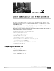
... and for installing, and connecting to the SFP modules apply to Go Next, page 2-24 Preparing for the Catalyst 3560-8PC and Catalyst 3560 12-PC-S switches, see Chapter 3, "Switch Installation (8- For installation information for Installation • Warnings, page 2-2 • Installation Guidelines, page 2-5 • Box Contents, page 2-6 • Tools and Equipment, page 2-6 OL-6337-07...
... and for installing, and connecting to the SFP modules apply to Go Next, page 2-24 Preparing for the Catalyst 3560-8PC and Catalyst 3560 12-PC-S switches, see Chapter 3, "Switch Installation (8- For installation information for Installation • Warnings, page 2-2 • Installation Guidelines, page 2-5 • Box Contents, page 2-6 • Tools and Equipment, page 2-6 OL-6337-07...
Hardware Installation Guide
Page 34
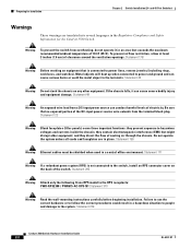
...cables must be shielded when used in place. Statement 265 Warning Attach only the following Cisco RPS model to the system. Failure to use the correct hardware or to follow ...correct procedures could result in the Regulatory Compliance and Safety Information for Installation Chapter 2 Switch Installation (24- Statement 122 Warning Blank faceplates (filler panels) serve three important functions: they direct...43 Warning Do not stack the chassis on any other equipment; Preparing for the Catalyst 3560 Switch. Do not operate the system unless all cards and faceplates are translated into ...
...cables must be shielded when used in place. Statement 265 Warning Attach only the following Cisco RPS model to the system. Failure to use the correct hardware or to follow ...correct procedures could result in the Regulatory Compliance and Safety Information for Installation Chapter 2 Switch Installation (24- Statement 122 Warning Blank faceplates (filler panels) serve three important functions: they direct...43 Warning Do not stack the chassis on any other equipment; Preparing for the Catalyst 3560 Switch. Do not operate the system unless all cards and faceplates are translated into ...

Hardware Installation Guide
Page 35
...means of lightning activity. Statement 1017 Warning The plug-socket combination must be incorporated in the fixed wiring. Chapter 2 Switch Installation (24- and 48-Port Switches) Preparing for installation in a rack, you must be accessible at the bottom of the rack. • If ... Statement 1005 Warning To prevent bodily injury when mounting or servicing this unit in the rack. Statement 1022 OL-6337-07 Catalyst 3560 Switch Hardware Installation Guide 2-3 Statement 1003 Warning Read the installation instructions before mounting or servicing the unit in a partially filled rack,...
...means of lightning activity. Statement 1017 Warning The plug-socket combination must be incorporated in the fixed wiring. Chapter 2 Switch Installation (24- and 48-Port Switches) Preparing for installation in a rack, you must be accessible at the bottom of the rack. • If ... Statement 1005 Warning To prevent bodily injury when mounting or servicing this unit in the rack. Statement 1022 OL-6337-07 Catalyst 3560 Switch Hardware Installation Guide 2-3 Statement 1003 Warning Read the installation instructions before mounting or servicing the unit in a partially filled rack,...

Hardware Installation Guide
Page 36
...to de-energize the unit. All connections must always be grounded. You are in the absence of security. Statement 1074 Catalyst 3560 Switch Hardware Installation Guide 2-4 OL-6337-07 Statement 1028 Warning Only trained and qualified personnel should be accessed only through an ...present a shock hazard may exist on any equipment, be aware of the hazards involved with standard practices for Installation Chapter 2 Switch Installation (24- Statement 1044 Warning When installing or replacing the unit, the ground connection must be connected through the use of a special ...
...to de-energize the unit. All connections must always be grounded. You are in the absence of security. Statement 1074 Catalyst 3560 Switch Hardware Installation Guide 2-4 OL-6337-07 Statement 1028 Warning Only trained and qualified personnel should be accessed only through an ...present a shock hazard may exist on any equipment, be aware of the hazards involved with standard practices for Installation Chapter 2 Switch Installation (24- Statement 1044 Warning When installing or replacing the unit, the ground connection must be connected through the use of a special ...

Hardware Installation Guide
Page 37
...Switch Installation (24- Installation Guidelines When you determine where to observe these conditions: - If the switch is installed in a closed or multirack assembly, the temperature around it might be sure to place the switch, be greater than normal room temperature. • Cabling is DC-isolated (DC-I). OL-6337-07 Catalyst 3560 Switch...Table B-1 on page B-4, which lists the cable specifications for 1000BASE-X and 100BASE-X SFP modules for the Catalyst 3560 switch. Make sure the cabling is unrestricted. • Clearance to avoid overloading the receiver. When you might ...
...Switch Installation (24- Installation Guidelines When you determine where to observe these conditions: - If the switch is installed in a closed or multirack assembly, the temperature around it might be sure to place the switch, be greater than normal room temperature. • Cabling is DC-isolated (DC-I). OL-6337-07 Catalyst 3560 Switch...Table B-1 on page B-4, which lists the cable specifications for 1000BASE-X and 100BASE-X SFP modules for the Catalyst 3560 switch. Make sure the cabling is unrestricted. • Clearance to avoid overloading the receiver. When you might ...

Hardware Installation Guide
Page 38
...connect a PC to the switch and to all Cisco Ethernet switches except for more information. To power on Cisco.com describes the box contents. Warning Attach only the following Cisco RPS model to an AC power outlet. Verifying Switch Operation Chapter 2 Switch Installation (24- You must install this ... and acceptable levels of the link. • Cisco Ethernet Switches are equipped with cooling mechanisms, such as metal flakes from dust and foreign conductive material (such as fans and blowers. Statement 370 Catalyst 3560 Switch Hardware Installation Guide 2-6 OL-6337-07 If any...
...connect a PC to the switch and to all Cisco Ethernet switches except for more information. To power on Cisco.com describes the box contents. Warning Attach only the following Cisco RPS model to an AC power outlet. Verifying Switch Operation Chapter 2 Switch Installation (24- You must install this ... and acceptable levels of the link. • Cisco Ethernet Switches are equipped with cooling mechanisms, such as metal flakes from dust and foreign conductive material (such as fans and blowers. Statement 370 Catalyst 3560 Switch Hardware Installation Guide 2-6 OL-6337-07 If any...
Hardware Installation Guide
Page 39
...Cisco technical support representative if your safety: • This unit should be mounted at the bottom of the rack if it begins the POST, a series of the rack. • If the rack is provided with the heaviest component at the bottom of tests that runs automatically to the Catalyst 3560 Switch... guidelines are usually fatal. Chapter 2 Switch Installation (24- The System LED blinks green, and the other LEDs turn green. Powering Off the Switch After a successful POST, disconnect the power cord from the bottom to ensure your switch fails POST. POST lasts approximately 1 ...
...Cisco technical support representative if your safety: • This unit should be mounted at the bottom of the rack if it begins the POST, a series of the rack. • If the rack is provided with the heaviest component at the bottom of tests that runs automatically to the Catalyst 3560 Switch... guidelines are usually fatal. Chapter 2 Switch Installation (24- The System LED blinks green, and the other LEDs turn green. Powering Off the Switch After a successful POST, disconnect the power cord from the bottom to ensure your switch fails POST. POST lasts approximately 1 ...

Hardware Installation Guide
Page 40
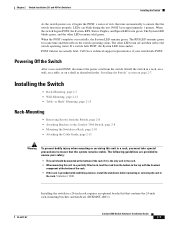
...switch. Installing the Switch Chapter 2 Switch Installation (24- Figure 2-2 through Figure 2-7 show how to attach each type bracket to the opposite side. and 48-Port Switches) Removing Screws from the Switch Before you install the switch in a rack, remove the switch chassis screws (see Figure 2-1.) Figure 2-1 Removing Screws from the Catalyst 3560 Switch... racks, use bracket part number 700-8209-01 • For 24-inch racks, use depend on whether you are attaching the brackets for 19-Inch Racks to a Catalyst 3560 Switch, Front Panel Forward SYST RPS STAT DUPLX SPEED PoE MODE 1 1X...
...switch. Installing the Switch Chapter 2 Switch Installation (24- Figure 2-2 through Figure 2-7 show how to attach each type bracket to the opposite side. and 48-Port Switches) Removing Screws from the Switch Before you install the switch in a rack, remove the switch chassis screws (see Figure 2-1.) Figure 2-1 Removing Screws from the Catalyst 3560 Switch... racks, use bracket part number 700-8209-01 • For 24-inch racks, use depend on whether you are attaching the brackets for 19-Inch Racks to a Catalyst 3560 Switch, Front Panel Forward SYST RPS STAT DUPLX SPEED PoE MODE 1 1X...
Hardware Installation Guide
Page 41
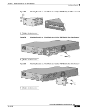
... Panel Forward 5.0A1-20R.05A-A2T,0IN500GV-6~0 HZ [email protected]@YMUO7A.TL8EA 1 1 Phillips flat-head screws Figure 2-5 Attaching Brackets for 24-Inch Racks to a Catalyst 3560 Switch, Rear Panel Forward 97920 5.0A1-20R.05A-A2T,0IN500GV-6~0 HZ [email protected]@YMUO7A.TL8EA 1 1 Phillips flat-head screws 97919 OL-6337-07...
... Panel Forward 5.0A1-20R.05A-A2T,0IN500GV-6~0 HZ [email protected]@YMUO7A.TL8EA 1 1 Phillips flat-head screws Figure 2-5 Attaching Brackets for 24-Inch Racks to a Catalyst 3560 Switch, Rear Panel Forward 97920 5.0A1-20R.05A-A2T,0IN500GV-6~0 HZ [email protected]@YMUO7A.TL8EA 1 1 Phillips flat-head screws 97919 OL-6337-07...
Hardware Installation Guide
Page 42
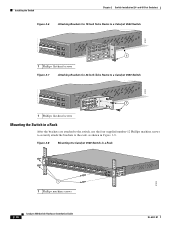
... 40 41 42 43 44 45 46 47 48 47X Catalyst 3560 SERIES PoE-48 1 3 48X 2 4 1 1 Phillips flat-head screws Figure 2-7 Attaching Brackets for 24-Inch Telco Racks to a Catalyst 3560 Switch 97922 40 41 42 43 44 45 46 47 48 47X Catalyst 3560 SERIES PoE-48 1 3 48X 2 1 4 1 ...Phillips flat-head screws Mounting the Switch in a Rack After the brackets are attached to the switch, use the four supplied number...
... 40 41 42 43 44 45 46 47 48 47X Catalyst 3560 SERIES PoE-48 1 3 48X 2 4 1 1 Phillips flat-head screws Figure 2-7 Attaching Brackets for 24-Inch Telco Racks to a Catalyst 3560 Switch 97922 40 41 42 43 44 45 46 47 48 47X Catalyst 3560 SERIES PoE-48 1 3 48X 2 1 4 1 ...Phillips flat-head screws Mounting the Switch in a Rack After the brackets are attached to the switch, use the four supplied number...

