
Installation Guide
Page 2
...is likely to cause harmful interference, in which case users will not occur in this product not authorized by Cisco Systems, Inc. These specifications are designed to this manual generates and may be required to correct the interference at your equipment is causing...B devices: The equipment described in a particular installation. Modifying the equipment without Cisco's written authorization may cause interference with FCC requirements for a Class B digital device in accordance with the specifications in the equipment no guarantee that is for FCC compliance of Class A devices...
...is likely to cause harmful interference, in which case users will not occur in this product not authorized by Cisco Systems, Inc. These specifications are designed to this manual generates and may be required to correct the interference at your equipment is causing...B devices: The equipment described in a particular installation. Modifying the equipment without Cisco's written authorization may cause interference with FCC requirements for a Class B digital device in accordance with the specifications in the equipment no guarantee that is for FCC compliance of Class A devices...

Installation Guide
Page 8
... B-1 1000BaseX Ports B-2 Gigastack Port B-3 Console Port B-3 Cable and Adapter Specifications B-4 Crossover and Straight-Through Cable Pinouts B-4 Rollover Cable and Adapter Pinouts B-5 Identifying a Rollover Cable B-5 Connecting to a PC B-6 Connecting to a Terminal B-7 Translated Safety Warnings C-1 Attaching the Cisco RPS (model PWR600-AC-RPS) C-2 Attaching the Cisco RPS (model PWR300-AC-RPS-N1) C-4 Service Personnel Warning...
... B-1 1000BaseX Ports B-2 Gigastack Port B-3 Console Port B-3 Cable and Adapter Specifications B-4 Crossover and Straight-Through Cable Pinouts B-4 Rollover Cable and Adapter Pinouts B-5 Identifying a Rollover Cable B-5 Connecting to a PC B-6 Connecting to a Terminal B-7 Translated Safety Warnings C-1 Attaching the Cisco RPS (model PWR600-AC-RPS) C-2 Attaching the Cisco RPS (model PWR300-AC-RPS-N1) C-4 Service Personnel Warning...

Installation Guide
Page 12
... describes how to set up the switch initial configuration. Appendix A, "Technical Specifications," lists the physical and environmental specifications for installing a switch on a rack, wall, table, or shelf. Appendix C, "Translated Safety Warnings," contains translations in various languages of the problems that can be installed suggest possible deployment strategies. Catalyst 3500 Series XL Hardware Installation Guide xii...
... describes how to set up the switch initial configuration. Appendix A, "Technical Specifications," lists the physical and environmental specifications for installing a switch on a rack, wall, table, or shelf. Appendix C, "Translated Safety Warnings," contains translations in various languages of the problems that can be installed suggest possible deployment strategies. Catalyst 3500 Series XL Hardware Installation Guide xii...

Installation Guide
Page 25
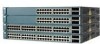
A feature specific to the Catalyst 3524-PWR XL switch is its ability to provide inline power to Cisco IP Phones. (Phone adapters are stackable 10/100 Ethernet switches to the Catalyst 3524-PWR XL 10/100 switch ports.) Figure 1-1 shows the switch models in different network topologies Features The Catalyst 3500 series XL switches-also referred to as Catalyst 3500 XL switches-are...
A feature specific to the Catalyst 3524-PWR XL switch is its ability to provide inline power to Cisco IP Phones. (Phone adapters are stackable 10/100 Ethernet switches to the Catalyst 3524-PWR XL 10/100 switch ports.) Figure 1-1 shows the switch models in different network topologies Features The Catalyst 3500 series XL switches-also referred to as Catalyst 3500 XL switches-are...

Installation Guide
Page 32
... B, "Connector and Cable Specifications." Front-Panel Description Chapter 1 Product Overview • 100BaseTX-compatible devices such as high-speed workstations, Cisco IP Phones, servers, hubs, routers, and other switches through , twisted-pair cable. Ports operating at 100 Mbps. When connecting the switch to switches or hubs, use Category ...Guide 1-8 78-6456-04 The 10/100 ports on the Catalyst 3512, 3524, 3524-PWR, and 3548 XL switches provide protocol support for inline power on the Catalyst 3512, 3524, and 3548 XL switches-must be explicitly set for the cables are described in ...
... B, "Connector and Cable Specifications." Front-Panel Description Chapter 1 Product Overview • 100BaseTX-compatible devices such as high-speed workstations, Cisco IP Phones, servers, hubs, routers, and other switches through , twisted-pair cable. Ports operating at 100 Mbps. When connecting the switch to switches or hubs, use Category ...Guide 1-8 78-6456-04 The 10/100 ports on the Catalyst 3512, 3524, 3524-PWR, and 3548 XL switches provide protocol support for inline power on the Catalyst 3512, 3524, and 3548 XL switches-must be explicitly set for the cables are described in ...

Installation Guide
Page 47
... source for each . Cisco RPS Connector Specific Cisco RPS models support specific Catalyst 3500 XL switches: • Cisco RPS 600 (model PWR600-AC-RPS)-Supports the Catalyst 3512, 3524, 3548, and 3508 XL switches • Cisco RPS 300 (model PWR300-AC-RPS)-Supports the Catalyst 3524-PWR XL switch RPS Connector on the Cisco RPS 600, refer to the Cisco Redundant Power System Hardware...
... source for each . Cisco RPS Connector Specific Cisco RPS models support specific Catalyst 3500 XL switches: • Cisco RPS 600 (model PWR600-AC-RPS)-Supports the Catalyst 3512, 3524, 3548, and 3508 XL switches • Cisco RPS 300 (model PWR300-AC-RPS)-Supports the Catalyst 3524-PWR XL switch RPS Connector on the Cisco RPS 600, refer to the Cisco Redundant Power System Hardware...

Installation Guide
Page 48
You use the Visual Switch Manager (VSM) application to the Cisco IOS Desktop Switching Software Configuration Guide and the online help for up of switches or an individual switch. For console port and adapter pinout information, see the "Cable and Adapter Specifications" section on the Cisco RPS 300, refer to ... Manager applications to create, configure, and monitor clusters. Management Options Chapter 1 Product Overview RPS Connector on the Catalyst 3524-PWR XL Switch The Cisco RPS 300 (model PWR300-AC-RPS) has two output levels: -48V and 12V with a total output power of the...
You use the Visual Switch Manager (VSM) application to the Cisco IOS Desktop Switching Software Configuration Guide and the online help for up of switches or an individual switch. For console port and adapter pinout information, see the "Cable and Adapter Specifications" section on the Cisco RPS 300, refer to ... Manager applications to create, configure, and monitor clusters. Management Options Chapter 1 Product Overview RPS Connector on the Catalyst 3524-PWR XL Switch The Cisco RPS 300 (model PWR300-AC-RPS) has two output levels: -48V and 12V with a total output power of the...

Installation Guide
Page 65
... document that came with your GBICs. • For the GigaStack GBIC ports, cable lengths from the switch to the connected devices are up to 1 meter. For specific cable lengths, refer to the documents that came with the GigaStack GBIC. • Operating environment is ...within the ranges listed in Appendix A, "Technical Specifications." 78-6456-04 Catalyst 3500 Series XL Hardware Installation Guide 2-7 Class A equipment is a class A product and should be sure to observe these guidelines: &#...
... document that came with your GBICs. • For the GigaStack GBIC ports, cable lengths from the switch to the connected devices are up to 1 meter. For specific cable lengths, refer to the documents that came with the GigaStack GBIC. • Operating environment is ...within the ranges listed in Appendix A, "Technical Specifications." 78-6456-04 Catalyst 3500 Series XL Hardware Installation Guide 2-7 Class A equipment is a class A product and should be sure to observe these guidelines: &#...

Installation Guide
Page 81
... port and adapter pinout information, see the "Cable and Adapter Specifications" section on the GigaStack GBIC connections and configuration scenarios, see the Catalyst GigaStack Gigabit Interface Converter Hardware Installation Guide. See the Cisco IOS Desktop Switching Software Configuration Guide for instructions. 78-6456-04 Catalyst 3500 Series XL Hardware Installation Guide 2-23 Follow these console...
... port and adapter pinout information, see the "Cable and Adapter Specifications" section on the GigaStack GBIC connections and configuration scenarios, see the Catalyst GigaStack Gigabit Interface Converter Hardware Installation Guide. See the Cisco IOS Desktop Switching Software Configuration Guide for instructions. 78-6456-04 Catalyst 3500 Series XL Hardware Installation Guide 2-23 Follow these console...

Installation Guide
Page 84
...you want to connect the switch console port to a terminal. For console port and adapter pinout information, see the "Cable and Adapter Specifications" section on page B-4....no ]: y If this procedure to the switch console port. Use the supplied rollover cable...switch: Note Be sure the rollover cable is connecting a PC serial port to create an initial configuration for the switch, and press Return: 2-26 Catalyst... 3500 Series XL Hardware Installation Guide 78-6456-04 Assigning Switch Information Chapter 2 Installing and Starting Up the Switch...
...you want to connect the switch console port to a terminal. For console port and adapter pinout information, see the "Cable and Adapter Specifications" section on page B-4....no ]: y If this procedure to the switch console port. Use the supplied rollover cable...switch: Note Be sure the rollover cable is connecting a PC serial port to create an initial configuration for the switch, and press Return: 2-26 Catalyst... 3500 Series XL Hardware Installation Guide 78-6456-04 Assigning Switch Information Chapter 2 Installing and Starting Up the Switch...

Installation Guide
Page 97
Table A-1 Technical Specifications for the Catalyst 3500 series XL switches. A A P P E N D I X Technical Specifications 78-6456-04 Table A-1, Table A-2, and Table A-3, list the technical specifications for the Catalyst 3508G XL Switch Environmental Ranges Operating temperature Storage temperature Operating humidity Operating altitude Storage altitude Power Requirements AC input voltage DC ...3A 82.2W 280 Btus per hour 12 lb (5.45 kg) 1.75 x 16 x 17.5 in. (4.45 x 40.46 x 44.45 cm) Catalyst 3500 Series XL Hardware Installation Guide A-1 Table A-4 lists the regulatory agency approvals.
Table A-1 Technical Specifications for the Catalyst 3500 series XL switches. A A P P E N D I X Technical Specifications 78-6456-04 Table A-1, Table A-2, and Table A-3, list the technical specifications for the Catalyst 3508G XL Switch Environmental Ranges Operating temperature Storage temperature Operating humidity Operating altitude Storage altitude Power Requirements AC input voltage DC ...3A 82.2W 280 Btus per hour 12 lb (5.45 kg) 1.75 x 16 x 17.5 in. (4.45 x 40.46 x 44.45 cm) Catalyst 3500 Series XL Hardware Installation Guide A-1 Table A-4 lists the regulatory agency approvals.

Installation Guide
Page 98
Appendix A Technical Specifications Table A-2 Technical Specifications for the Catalyst 3512, 3524, and 3548 XL Switches Catalyst 3512 XL Catalyst 3524 XL Catalyst 3548 XL Environmental Ranges Operating temperature 32 to 113°F (0 to 45°C) 32 to 113°F (0 to 45°C) 32 to 113°F (0 to ....82 x 17.5 in. 1.73 x 15.34 x 17.5 in D x W) (4.45 x 30.02 x 44.45 cm) (4.45 x 30.02 x 44.45 cm) (4.39 x 39.0 x 44.45 cm) Catalyst 3500 Series XL Hardware Installation Guide A-2 78-6456-04
Appendix A Technical Specifications Table A-2 Technical Specifications for the Catalyst 3512, 3524, and 3548 XL Switches Catalyst 3512 XL Catalyst 3524 XL Catalyst 3548 XL Environmental Ranges Operating temperature 32 to 113°F (0 to 45°C) 32 to 113°F (0 to 45°C) 32 to 113°F (0 to ....82 x 17.5 in. 1.73 x 15.34 x 17.5 in D x W) (4.45 x 30.02 x 44.45 cm) (4.45 x 30.02 x 44.45 cm) (4.39 x 39.0 x 44.45 cm) Catalyst 3500 Series XL Hardware Installation Guide A-2 78-6456-04

Installation Guide
Page 99
...Dimensions (H x W x D) 1.75 x 11.82 x 17.5 in. (4.45 x 30.02 x 44.45 cm) 1. Appendix A Technical Specifications Table A-3 Technical Specifications for the Catalyst 3524-PWR XL Switch Environmental Ranges Operating temperature 32 to 113°F (0 to 45°C) Storage temperature -4 to 149°F (-10 to 65°C) Operating humidity... 100 to 127/200 to 240 VAC (autoranging) 50 to NOM-019-SCFI CE Marking CE Marking 78-6456-04 Catalyst 3500 Series XL Hardware Installation Guide A-3 The actual power consumption depends on the number of IP phones connected. 325W represents 24...
...Dimensions (H x W x D) 1.75 x 11.82 x 17.5 in. (4.45 x 30.02 x 44.45 cm) 1. Appendix A Technical Specifications Table A-3 Technical Specifications for the Catalyst 3524-PWR XL Switch Environmental Ranges Operating temperature 32 to 113°F (0 to 45°C) Storage temperature -4 to 149°F (-10 to 65°C) Operating humidity... 100 to 127/200 to 240 VAC (autoranging) 50 to NOM-019-SCFI CE Marking CE Marking 78-6456-04 Catalyst 3500 Series XL Hardware Installation Guide A-3 The actual power consumption depends on the number of IP phones connected. 325W represents 24...

Installation Guide
Page 100
Appendix A Technical Specifications Catalyst 3500 Series XL Hardware Installation Guide A-4 78-6456-04
Appendix A Technical Specifications Catalyst 3500 Series XL Hardware Installation Guide A-4 78-6456-04

Installation Guide
Page 101
...Cisco IP Phones, you use a crossover cable. (Figure B-4 illustrates the crossover cable schematics.) Note Use a straight-through cable schematics). Figure B-1 shows the pinout. When connecting to other devices. APPENDIX B Connector and Cable Specifications This appendix describes the Catalyst 3500 XL switch... ports and the cables and adapters that you use to connect the switch to other switches or repeaters, ensure that a straight-through cable and ...
...Cisco IP Phones, you use a crossover cable. (Figure B-4 illustrates the crossover cable schematics.) Note Use a straight-through cable schematics). Figure B-1 shows the pinout. When connecting to other devices. APPENDIX B Connector and Cable Specifications This appendix describes the Catalyst 3500 XL switch... ports and the cables and adapters that you use to connect the switch to other switches or repeaters, ensure that a straight-through cable and ...

Installation Guide
Page 102
Connector Specifications Appendix B Connector and Cable Specifications Figure B-1 10/100 Port Pinouts Pin Label 1 RD+ 2 RD- 3 TD+ 4 NC 5 NC 6 TD- 7 NC 8 NC 12345678 H5318 1000BaseX Ports 1000BaseX ports use duplex SC connectors, as shown in Figure B-2. Figure B-2 1000BaseX SC Connector H8707 Tx Rx Catalyst 3500 Series XL Hardware Installation Guide B-2 78-6456-04
Connector Specifications Appendix B Connector and Cable Specifications Figure B-1 10/100 Port Pinouts Pin Label 1 RD+ 2 RD- 3 TD+ 4 NC 5 NC 6 TD- 7 NC 8 NC 12345678 H5318 1000BaseX Ports 1000BaseX ports use duplex SC connectors, as shown in Figure B-2. Figure B-2 1000BaseX SC Connector H8707 Tx Rx Catalyst 3500 Series XL Hardware Installation Guide B-2 78-6456-04

Installation Guide
Page 103
... and Cable Specifications Connector Specifications Gigastack Port The...ACS-DSBUASYN=) containing that adapter from Cisco. Figure B-3 GigaStack Connector 22084 The GigaStack GBIC cables are used to connect the console port of the switch to a terminal. Console Port ...The console port uses an 8-pin RJ-45 connector, described in Figure B-3. Caution Do not use standard IEEE 1394 cables with enhanced signal integrity and EMI performance. For console port and adapter pinout information, see Table B-1 and Table B-2. 78-6456-04 Catalyst...
... and Cable Specifications Connector Specifications Gigastack Port The...ACS-DSBUASYN=) containing that adapter from Cisco. Figure B-3 GigaStack Connector 22084 The GigaStack GBIC cables are used to connect the console port of the switch to a terminal. Console Port ...The console port uses an 8-pin RJ-45 connector, described in Figure B-3. Caution Do not use standard IEEE 1394 cables with enhanced signal integrity and EMI performance. For console port and adapter pinout information, see Table B-1 and Table B-2. 78-6456-04 Catalyst...

Installation Guide
Page 104
Figure B-4 Crossover Cable Schematic Switch 3 TD+ 6 TD- Switch 3 TD+ 6 TD- 1 RD+ 2 RD- 1 RD+ 2 RD- H5579 Figure B-5 Straight-Through Cable Schematic Switch 3 TD+ 6 TD- H5578 Catalyst 3500 Series XL Hardware Installation Guide B-4 78-6456-04 Cable and Adapter Specifications Appendix B Connector and Cable Specifications Cable and Adapter Specifications Crossover and Straight-Through Cable Pinouts The schematics of crossover and straight-through cables are shown in Figure B-4 and Figure B-5. Switch 3 RD+ 6 RD- 1 RD+ 2 RD- 1 TD+ 2 TD-
Figure B-4 Crossover Cable Schematic Switch 3 TD+ 6 TD- Switch 3 TD+ 6 TD- 1 RD+ 2 RD- 1 RD+ 2 RD- H5579 Figure B-5 Straight-Through Cable Schematic Switch 3 TD+ 6 TD- H5578 Catalyst 3500 Series XL Hardware Installation Guide B-4 78-6456-04 Cable and Adapter Specifications Appendix B Connector and Cable Specifications Cable and Adapter Specifications Crossover and Straight-Through Cable Pinouts The schematics of crossover and straight-through cables are shown in Figure B-4 and Figure B-5. Switch 3 RD+ 6 RD- 1 RD+ 2 RD- 1 TD+ 2 TD-

Installation Guide
Page 105
... wire connected to the pin on the outside of the right plug (see Figure B-6). Pin 8 H10632 78-6456-04 Catalyst 3500 Series XL Hardware Installation Guide B-5 Appendix B Connector and Cable Specifications Cable and Adapter Specifications Rollover Cable and Adapter Pinouts Identifying a Rollover Cable To identify a rollover cable, compare the two modular ends of...
... wire connected to the pin on the outside of the right plug (see Figure B-6). Pin 8 H10632 78-6456-04 Catalyst 3500 Series XL Hardware Installation Guide B-5 Appendix B Connector and Cable Specifications Cable and Adapter Specifications Rollover Cable and Adapter Pinouts Identifying a Rollover Cable To identify a rollover cable, compare the two modular ends of...

Installation Guide
Page 106
... 5 3 4 7 Console Device Signal CTS DSR RxD GND GND TxD DTR RTS Catalyst 3500 Series XL Hardware Installation Guide B-6 78-6456-04 Figure B-7 Connecting the Console Port to a PC PC Catalyst 3500 series XL switch 22003 RJ-45-to-RJ-45 rollover cable RJ-45-to-DB-9 adapter (labeled ...7 TxD 3 6 GND 4 5 GND 5 4 RxD 6 3 Not connected 7 2 CTS 8 1 RJ-45-to -DB-9 female DTE adapter. Cable and Adapter Specifications Appendix B Connector and Cable Specifications Connecting to a PC Use the supplied thin, flat, RJ-45-to-RJ-45 rollover cable and RJ-45-to-DB-9 female DTE adapter...
... 5 3 4 7 Console Device Signal CTS DSR RxD GND GND TxD DTR RTS Catalyst 3500 Series XL Hardware Installation Guide B-6 78-6456-04 Figure B-7 Connecting the Console Port to a PC PC Catalyst 3500 series XL switch 22003 RJ-45-to-RJ-45 rollover cable RJ-45-to-DB-9 adapter (labeled ...7 TxD 3 6 GND 4 5 GND 5 4 RxD 6 3 Not connected 7 2 CTS 8 1 RJ-45-to -DB-9 female DTE adapter. Cable and Adapter Specifications Appendix B Connector and Cable Specifications Connecting to a PC Use the supplied thin, flat, RJ-45-to-RJ-45 rollover cable and RJ-45-to-DB-9 female DTE adapter...