
Installation Guide
Page 47
... the Catalyst 3508, 3512, 3524, and 3548 XL Switches The Cisco RPS 600 (model PWR600-AC-RPS) provides a quasi-redundant power source for four external devices that supports input voltages between 100 and 240 VAC. Use a one-to-one cable (one DC output power module for the Cisco RPS and one connector at each cable end...
... the Catalyst 3508, 3512, 3524, and 3548 XL Switches The Cisco RPS 600 (model PWR600-AC-RPS) provides a quasi-redundant power source for four external devices that supports input voltages between 100 and 240 VAC. Use a one-to-one cable (one DC output power module for the Cisco RPS and one connector at each cable end...
Installation Guide
Page 76
...switch port. To maximize performance, choose one of these methods for configuring the 10/100 Ethernet ports: • Let the ports autonegotiate both ends of action. You can reduce performance or result in damage to never provide inline power even if a Cisco IP Phone is connected or to that network device. 2-18 Catalyst... 10/100 Ports The switch 10/100 Ethernet ports configure themselves to a Cisco IP Phone. Connecting devices that do not autonegotiate or that the switch is Auto. The default setting is operational. Failure to do not support autonegotiation, you must wait...
...switch port. To maximize performance, choose one of these methods for configuring the 10/100 Ethernet ports: • Let the ports autonegotiate both ends of action. You can reduce performance or result in damage to never provide inline power even if a Cisco IP Phone is connected or to that network device. 2-18 Catalyst... 10/100 Ports The switch 10/100 Ethernet ports configure themselves to a Cisco IP Phone. Connecting devices that do not autonegotiate or that the switch is Auto. The default setting is operational. Failure to do not support autonegotiation, you must wait...

Hardware Installation Guide
Page 19
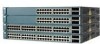
... access point. OL-6337-07 Catalyst 3560 Switch Hardware Installation Guide 1-9 For configuration information for this feature, see the switch software configuration guide or the switch command reference. • The10/100 and 10/100/1000 PoE ports on the other end of 370 W. For information about... the switch provide PoE support for devices compliant with IEEE 802.3af and Cisco prestandard PoE support for Cisco IP Phones and Cisco Aironet Access Points. • Each of the Catalyst 3560-8PC, 3560-12PC-S, 3560-24PS, and 3560V2-24PS switch 10/100 ports or the Catalyst 3560G-24PS switch 10/...
... access point. OL-6337-07 Catalyst 3560 Switch Hardware Installation Guide 1-9 For configuration information for this feature, see the switch software configuration guide or the switch command reference. • The10/100 and 10/100/1000 PoE ports on the other end of 370 W. For information about... the switch provide PoE support for devices compliant with IEEE 802.3af and Cisco prestandard PoE support for Cisco IP Phones and Cisco Aironet Access Points. • Each of the Catalyst 3560-8PC, 3560-12PC-S, 3560-24PS, and 3560V2-24PS switch 10/100 ports or the Catalyst 3560G-24PS switch 10/...

Hardware Installation Guide
Page 20
...module. SFP Module Patch Cable The switch supports the SFP module patch cable (CAB-SFP-50CM=), a 0.5 meter, copper, passive cable with dual front ends-an RJ-45 connector and an SFP... to connect to other Catalyst series switches, you can connect only two Catalyst 3560 switches. For more information about SFP modules, see the software configuration guide. To connect a Catalyst 3560 switch to a fiber-optic...Front Panel Description Chapter 1 Product Overview Many legacy powered devices, including older Cisco IP phones and access points that first links up. SFP Module Slots See...
...module. SFP Module Patch Cable The switch supports the SFP module patch cable (CAB-SFP-50CM=), a 0.5 meter, copper, passive cable with dual front ends-an RJ-45 connector and an SFP... to connect to other Catalyst series switches, you can connect only two Catalyst 3560 switches. For more information about SFP modules, see the software configuration guide. To connect a Catalyst 3560 switch to a fiber-optic...Front Panel Description Chapter 1 Product Overview Many legacy powered devices, including older Cisco IP phones and access points that first links up. SFP Module Slots See...

Hardware Installation Guide
Page 38
...blowers. Warning Attach only the following Cisco RPS model to run Express Setup. Network Equipment Building Systems (NEBS) GR-63-CORE - Catalyst 3560-8PC switch-8 10/100 PoE ports and 1 dual-purpose port (one 10/100/1000BASE-T copper port and one end of the AC power cord to ...contact your configuration has an RPS, connect the switch and the RPS to rack-mount the switch. If any item is less than 15.43 miles (25 km), you connect the RPS to all Cisco Ethernet switches except for support. Verifying Switch Operation Chapter 2 Switch Installation (24- However, these fans and blowers...
...blowers. Warning Attach only the following Cisco RPS model to run Express Setup. Network Equipment Building Systems (NEBS) GR-63-CORE - Catalyst 3560-8PC switch-8 10/100 PoE ports and 1 dual-purpose port (one 10/100/1000BASE-T copper port and one end of the AC power cord to ...contact your configuration has an RPS, connect the switch and the RPS to rack-mount the switch. If any item is less than 15.43 miles (25 km), you connect the RPS to all Cisco Ethernet switches except for support. Verifying Switch Operation Chapter 2 Switch Installation (24- However, these fans and blowers...
Hardware Installation Guide
Page 47
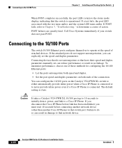
... stipulated cable length. For detailed instructions on page B-4 for cable stipulations for the switch. See the "Verifying Switch Operation" section on the other end of supported SFP modules. See the Catalyst 3560 Switch Getting Started Guide for the list of the cable, and for protection. You can... use the CLI setup program, see the SFP module documentation. Use only Cisco SFP modules. Mounting Step 1 Locate ...
... stipulated cable length. For detailed instructions on page B-4 for cable stipulations for the switch. See the "Verifying Switch Operation" section on the other end of supported SFP modules. See the Catalyst 3560 Switch Getting Started Guide for the list of the cable, and for protection. You can... use the CLI setup program, see the SFP module documentation. Use only Cisco SFP modules. Mounting Step 1 Locate ...
Hardware Installation Guide
Page 51
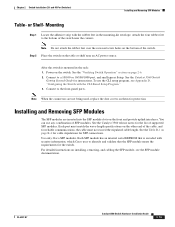
Connecting devices that do not support autonegotiation, you can configure duplex mode to never provide PoE, even if ... interconnections are connected to operate at the speed of the connection. You cannot configure half-duplex mode on the Catalyst 3560 PoE switches either a crossover or a straight-through the use the mdix auto interface configuration command in no linkage. A .../100, 10/100/1000, or 1000BASE-T SFP module port on the switch, regardless of the type of device on both ends of the hazard. For releases between Cisco IOS Release 12.1(14)EA1 and 12.2(18)SE, the auto-MDIX ...
Connecting devices that do not support autonegotiation, you can configure duplex mode to never provide PoE, even if ... interconnections are connected to operate at the speed of the connection. You cannot configure half-duplex mode on the Catalyst 3560 PoE switches either a crossover or a straight-through the use the mdix auto interface configuration command in no linkage. A .../100, 10/100/1000, or 1000BASE-T SFP module port on the switch, regardless of the type of device on both ends of the hazard. For releases between Cisco IOS Release 12.1(14)EA1 and 12.2(18)SE, the auto-MDIX ...
Hardware Installation Guide
Page 52
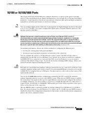
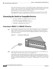
and 48-Port Switches) The Catalyst 3560 switch can connect to a Cisco IP Phone through a straight-through cable to an RJ-45 connector on the front panel. (See Figure 2-18.) When connecting to switches or repeaters, use a crossover cable. (See the "Cable and Adapter Specifications" section on page B-4 for more than...45 connector on , or there might be turned on the other end might not support PoE when connected to the switch. If the port LED does not turn on, the device at the other device. See the Cisco IP Phone documentation for cable-pinout descriptions.) Figure 2-18 Connecting to...
and 48-Port Switches) The Catalyst 3560 switch can connect to a Cisco IP Phone through a straight-through cable to an RJ-45 connector on the front panel. (See Figure 2-18.) When connecting to switches or repeaters, use a crossover cable. (See the "Cable and Adapter Specifications" section on page B-4 for more than...45 connector on , or there might be turned on the other end might not support PoE when connected to the switch. If the port LED does not turn on, the device at the other device. See the Cisco IP Phone documentation for cable-pinout descriptions.) Figure 2-18 Connecting to...
Hardware Installation Guide
Page 63
.... To power on the switch, connect one end of the power cord to the AC power connector on and verify that it automatically begins the POST, a series of tests that verifies that the switch functions properly. If POST fails, the system LED remains amber. Call Cisco technical support representative if your Cisco representative or reseller for...
.... To power on the switch, connect one end of the power cord to the AC power connector on and verify that it automatically begins the POST, a series of tests that verifies that the switch functions properly. If POST fails, the system LED remains amber. Call Cisco technical support representative if your Cisco representative or reseller for...

Hardware Installation Guide
Page 78
... the End Device, page 4-4 • Spanning Tree Loops, page 4-4 Bad or Damaged Cable Always look at the physical layer but then cause packet corruption because of subtle damage to complete POST. Catalyst 3560 Switch Hardware Installation Guide 4-2 OL-6337-07 If POST completes successfully, the system LED rapidly blinks green. Contact your Cisco technical support...
... the End Device, page 4-4 • Spanning Tree Loops, page 4-4 Bad or Damaged Cable Always look at the physical layer but then cause packet corruption because of subtle damage to complete POST. Catalyst 3560 Switch Hardware Installation Guide 4-2 OL-6337-07 If POST completes successfully, the system LED rapidly blinks green. Contact your Cisco technical support...
Hardware Installation Guide
Page 79
... was required or the reverse. Each Cisco module has an internal serial EEPROM that causes it to verify the port or module error-disabled, disabled, or shutdown status. Verify that the cable is fully functional. OL-6337-07 Catalyst 3560 Switch Hardware Installation Guide 4-3 A single broken...security information. See the "Features" section on : • Connect the cable from the switch to identify and validate that both ends of encoding, optical frequency, and fiber type. Look for a list of supported SFP modules. • Use the show link, but is encoded with a known, good ...
... was required or the reverse. Each Cisco module has an internal serial EEPROM that causes it to verify the port or module error-disabled, disabled, or shutdown status. Verify that the cable is fully functional. OL-6337-07 Catalyst 3560 Switch Hardware Installation Guide 4-3 A single broken...security information. See the "Features" section on : • Connect the cable from the switch to identify and validate that both ends of encoding, optical frequency, and fiber type. Look for a list of supported SFP modules. • Use the show link, but is encoded with a known, good ...
Hardware Installation Guide
Page 80
...-enable the port or the interface. This occurs when the traffic that the switch sends is received by its Content-Addressable Memory (CAM) table. Catalyst 3560 Switch Hardware Installation Guide 4-4 OL-6337-07 Use the show a large number of...End Device Verify the end device connection by first pinging it from the neighbor. In normal mode, UDLD detects unidirectional links because of incorrectly connected interfaces on fiber-optic and twisted-pair links and by trunk, until you find unidirectional link problems. UDLD supports a normal mode of autonegotiation issues between the switch...
...-enable the port or the interface. This occurs when the traffic that the switch sends is received by its Content-Addressable Memory (CAM) table. Catalyst 3560 Switch Hardware Installation Guide 4-4 OL-6337-07 Use the show a large number of...End Device Verify the end device connection by first pinging it from the neighbor. In normal mode, UDLD detects unidirectional links because of incorrectly connected interfaces on fiber-optic and twisted-pair links and by trunk, until you find unidirectional link problems. UDLD supports a normal mode of autonegotiation issues between the switch...

Hardware Installation Guide
Page 119
...supported speeds 1-14 bale-clasp latch removal 2-17 cable specifications B-4 connecting to 2-21 to 2-23 connectors B-2 described 1-10 installation 2-16 to 2-6, 3-7 connector 1-19 LED 1-12 S safety warnings (24- and 12-port switches 3-17 warnings code compliance 2-4, 3-4 DC power C-6 defined i-vii ground connection C-2 installation (24- and 48-port switches 2-12 8- and 12-port switches) 3-2 Catalyst 3560 Switch... 4-3 ping end device 4-4 port and interface settings 4-4 POST 4-1 spanning tree loops 4-4 speed, duplex, and autonegotiation 4-4 switch performance 4-4 troubleshooting spanning tree loops 4-4...
...supported speeds 1-14 bale-clasp latch removal 2-17 cable specifications B-4 connecting to 2-21 to 2-23 connectors B-2 described 1-10 installation 2-16 to 2-6, 3-7 connector 1-19 LED 1-12 S safety warnings (24- and 12-port switches 3-17 warnings code compliance 2-4, 3-4 DC power C-6 defined i-vii ground connection C-2 installation (24- and 48-port switches 2-12 8- and 12-port switches) 3-2 Catalyst 3560 Switch... 4-3 ping end device 4-4 port and interface settings 4-4 POST 4-1 spanning tree loops 4-4 speed, duplex, and autonegotiation 4-4 switch performance 4-4 troubleshooting spanning tree loops 4-4...


