
Installation Guide
Page 2
... generates and may cause interference with the limits for a Class B digital device in accordance with the specifications in this product not authorized by the Cisco equipment or one side or the other of its peripheral devices. If it may radiate radio-frequency energy...provide reasonable protection against such interference in a residential installation. If the interference stops, it off. Operation of the FCC rules. These specifications are on a different circuit from the television or radio. (That is on circuits controlled by the University of California, Berkeley (...
... generates and may cause interference with the limits for a Class B digital device in accordance with the specifications in this product not authorized by the Cisco equipment or one side or the other of its peripheral devices. If it may radiate radio-frequency energy...provide reasonable protection against such interference in a residential installation. If the interference stops, it off. Operation of the FCC rules. These specifications are on a different circuit from the television or radio. (That is on circuits controlled by the University of California, Berkeley (...

Installation Guide
Page 8
... B-1 1000BaseX Ports B-2 Gigastack Port B-3 Console Port B-3 Cable and Adapter Specifications B-4 Crossover and Straight-Through Cable Pinouts B-4 Rollover Cable and Adapter Pinouts B-5 Identifying a Rollover Cable B-5 Connecting to a PC B-6 Connecting to a Terminal B-7 Translated Safety Warnings C-1 Attaching the Cisco RPS (model PWR600-AC-RPS) C-2 Attaching the Cisco RPS (model PWR300-AC-RPS-N1) C-4 Service Personnel Warning...
... B-1 1000BaseX Ports B-2 Gigastack Port B-3 Console Port B-3 Cable and Adapter Specifications B-4 Crossover and Straight-Through Cable Pinouts B-4 Rollover Cable and Adapter Pinouts B-5 Identifying a Rollover Cable B-5 Connecting to a PC B-6 Connecting to a Terminal B-7 Translated Safety Warnings C-1 Attaching the Cisco RPS (model PWR600-AC-RPS) C-2 Attaching the Cisco RPS (model PWR300-AC-RPS-N1) C-4 Service Personnel Warning...

Installation Guide
Page 12
..., such as passwords or tabs, are in this guide. Examples of the warnings in angle brackets (< >). Catalyst 3500 Series XL Hardware Installation Guide xii 78-6456-04 Appendix A, "Technical Specifications," lists the physical and environmental specifications for installing a switch on a rack, wall, table, or shelf. Conventions This guide uses the following chapters: Chapter 1, "Product...
..., such as passwords or tabs, are in this guide. Examples of the warnings in angle brackets (< >). Catalyst 3500 Series XL Hardware Installation Guide xii 78-6456-04 Appendix A, "Technical Specifications," lists the physical and environmental specifications for installing a switch on a rack, wall, table, or shelf. Conventions This guide uses the following chapters: Chapter 1, "Product...

Installation Guide
Page 25
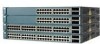
A feature specific to the Catalyst 3524-PWR XL switch is its ability to provide inline power to Cisco IP Phones. (Phone adapters are stackable 10/100 Ethernet switches to the Catalyst 3524-PWR XL 10/100 switch ports.) Figure 1-1 shows the switch models in the series, and Table 1-1 and Table 1-2 list their features. 78-6456-04 Catalyst 3500 Series XL...
A feature specific to the Catalyst 3524-PWR XL switch is its ability to provide inline power to Cisco IP Phones. (Phone adapters are stackable 10/100 Ethernet switches to the Catalyst 3524-PWR XL 10/100 switch ports.) Figure 1-1 shows the switch models in the series, and Table 1-1 and Table 1-2 list their features. 78-6456-04 Catalyst 3500 Series XL...

Installation Guide
Page 32
... Appendix B, "Connector and Cable Specifications." However, the Catalyst 3524-PWR XL 10/100 ports can: • Provide -48V DC power to an AC power source. When connecting the switch to workstations, servers, routers, and Cisco IP Phones, be connected to the following phones: Cisco IP Phone 7960, Cisco IP Phone 7940, and Cisco IP Phone 7910 •...
... Appendix B, "Connector and Cable Specifications." However, the Catalyst 3524-PWR XL 10/100 ports can: • Provide -48V DC power to an AC power source. When connecting the switch to workstations, servers, routers, and Cisco IP Phones, be connected to the following phones: Cisco IP Phone 7960, Cisco IP Phone 7940, and Cisco IP Phone 7910 •...

Installation Guide
Page 47
... each external device. Cisco RPS Connector Specific Cisco RPS models support specific Catalyst 3500 XL switches: • Cisco RPS 600 (model PWR600-AC-RPS)-Supports the Catalyst 3512, 3524, 3548, and 3508 XL switches • Cisco RPS 300 (model PWR300-AC-RPS)-Supports the Catalyst 3524-PWR XL switch RPS Connector on the Cisco RPS 600, refer to the Cisco Redundant Power System Hardware...
... each external device. Cisco RPS Connector Specific Cisco RPS models support specific Catalyst 3500 XL switches: • Cisco RPS 600 (model PWR600-AC-RPS)-Supports the Catalyst 3512, 3524, 3548, and 3508 XL switches • Cisco RPS 300 (model PWR300-AC-RPS)-Supports the Catalyst 3524-PWR XL switch RPS Connector on the Cisco RPS 600, refer to the Cisco Redundant Power System Hardware...

Installation Guide
Page 48
...Cable and Adapter Specifications" section on page B-4. You use the Visual Switch Manager (VSM) application to manage individual and standalone switches. For more information, refer to the Cisco IOS Desktop Switching Software Configuration Guide and the online help for up of switches or an individual switch. You need... create, monitor, and configure a cluster of four web-based applications that adapter from Cisco. Management Options Chapter 1 Product Overview RPS Connector on the Catalyst 3524-PWR XL Switch The Cisco RPS 300 (model PWR300-AC-RPS) has two output levels: -48V and 12V...
...Cable and Adapter Specifications" section on page B-4. You use the Visual Switch Manager (VSM) application to manage individual and standalone switches. For more information, refer to the Cisco IOS Desktop Switching Software Configuration Guide and the online help for up of switches or an individual switch. You need... create, monitor, and configure a cluster of four web-based applications that adapter from Cisco. Management Options Chapter 1 Product Overview RPS Connector on the Catalyst 3524-PWR XL Switch The Cisco RPS 300 (model PWR300-AC-RPS) has two output levels: -48V and 12V...

Installation Guide
Page 65
... GBIC ports, cable lengths from the switch to the connected devices are up to 1 meter. Class A equipment is designed for typical commercial establishments for Installation Warning This equipment is within the ranges listed in Appendix A, "Technical Specifications." 78-6456-04 Catalyst 3500 Series XL Hardware Installation Guide 2-7 For specific cable lengths, refer to the...
... GBIC ports, cable lengths from the switch to the connected devices are up to 1 meter. Class A equipment is designed for typical commercial establishments for Installation Warning This equipment is within the ranges listed in Appendix A, "Technical Specifications." 78-6456-04 Catalyst 3500 Series XL Hardware Installation Guide 2-7 For specific cable lengths, refer to the...

Installation Guide
Page 81
...change the port baud rate. The PC or terminal must support VT100 terminal emulation. See the Cisco IOS Desktop Switching Software Configuration Guide for instructions. 78-6456-04 Catalyst 3500 Series XL Hardware Installation Guide 2-23 Connecting a PC or Terminal to the Console Port... switch, you want to connect the switch console port to the switch console port. Chapter 2 Installing and Starting Up the Switch Connecting a PC or Terminal to the Console Port For more information on the GigaStack GBIC connections and configuration scenarios, see the "Cable and Adapter Specifications"...
...change the port baud rate. The PC or terminal must support VT100 terminal emulation. See the Cisco IOS Desktop Switching Software Configuration Guide for instructions. 78-6456-04 Catalyst 3500 Series XL Hardware Installation Guide 2-23 Connecting a PC or Terminal to the Console Port... switch, you want to connect the switch console port to the switch console port. Chapter 2 Installing and Starting Up the Switch Connecting a PC or Terminal to the Console Port For more information on the GigaStack GBIC connections and configuration scenarios, see the "Cable and Adapter Specifications"...

Installation Guide
Page 84
...switch, and press Return: 2-26 Catalyst 3500 Series XL Hardware Installation Guide 78-6456-04 Enter setup, and press Return to the switch console port. You can order a kit (part number ACS-DSBUASYN=) containing that adapter from Cisco.... Use the supplied rollover cable and DB-9 adapter to connect a PC to restart the setup program. Assigning Switch Information Chapter 2 Installing and Starting Up the Switch...switch: Note Be sure the rollover cable is connecting a PC serial port to a terminal. Enter the switch...to connect the switch console port to the switch console port. ...
...switch, and press Return: 2-26 Catalyst 3500 Series XL Hardware Installation Guide 78-6456-04 Enter setup, and press Return to the switch console port. You can order a kit (part number ACS-DSBUASYN=) containing that adapter from Cisco.... Use the supplied rollover cable and DB-9 adapter to connect a PC to restart the setup program. Assigning Switch Information Chapter 2 Installing and Starting Up the Switch...switch: Note Be sure the rollover cable is connecting a PC serial port to a terminal. Enter the switch...to connect the switch console port to the switch console port. ...

Installation Guide
Page 97
Table A-1 Technical Specifications for the Catalyst 3500 series XL switches. Table A-4 lists the regulatory agency approvals. A A P P E N D I X Technical Specifications 78-6456-04 Table A-1, Table A-2, and Table A-3, list the technical specifications for the Catalyst 3508G XL Switch Environmental Ranges Operating temperature Storage temperature Operating humidity Operating altitude Storage altitude Power Requirements AC input voltage ... @3A 82.2W 280 Btus per hour 12 lb (5.45 kg) 1.75 x 16 x 17.5 in. (4.45 x 40.46 x 44.45 cm) Catalyst 3500 Series XL Hardware Installation Guide A-1
Table A-1 Technical Specifications for the Catalyst 3500 series XL switches. Table A-4 lists the regulatory agency approvals. A A P P E N D I X Technical Specifications 78-6456-04 Table A-1, Table A-2, and Table A-3, list the technical specifications for the Catalyst 3508G XL Switch Environmental Ranges Operating temperature Storage temperature Operating humidity Operating altitude Storage altitude Power Requirements AC input voltage ... @3A 82.2W 280 Btus per hour 12 lb (5.45 kg) 1.75 x 16 x 17.5 in. (4.45 x 40.46 x 44.45 cm) Catalyst 3500 Series XL Hardware Installation Guide A-1

Installation Guide
Page 98
Appendix A Technical Specifications Table A-2 Technical Specifications for the Catalyst 3512, 3524, and 3548 XL Switches Catalyst 3512 XL Catalyst 3524 XL Catalyst 3548 XL Environmental Ranges Operating temperature 32 to 113°F (0 to 45°C) 32 to 113°F (0 to 45°C) 32 to 113°F (0 to ....82 x 17.5 in. 1.73 x 15.34 x 17.5 in D x W) (4.45 x 30.02 x 44.45 cm) (4.45 x 30.02 x 44.45 cm) (4.39 x 39.0 x 44.45 cm) Catalyst 3500 Series XL Hardware Installation Guide A-2 78-6456-04
Appendix A Technical Specifications Table A-2 Technical Specifications for the Catalyst 3512, 3524, and 3548 XL Switches Catalyst 3512 XL Catalyst 3524 XL Catalyst 3548 XL Environmental Ranges Operating temperature 32 to 113°F (0 to 45°C) 32 to 113°F (0 to 45°C) 32 to 113°F (0 to ....82 x 17.5 in. 1.73 x 15.34 x 17.5 in D x W) (4.45 x 30.02 x 44.45 cm) (4.45 x 30.02 x 44.45 cm) (4.39 x 39.0 x 44.45 cm) Catalyst 3500 Series XL Hardware Installation Guide A-2 78-6456-04

Installation Guide
Page 99
The actual power consumption depends on the number of IP phones connected. 325W represents 24 IP phones connected. Table A-4 Catalyst 3500 Series XL Agency Approvals Safety EMC UL to UL 1950, Third Edition FCC Part 15 Class A c-UL to CAN/...65 kg) Dimensions (H x W x D) 1.75 x 11.82 x 17.5 in. (4.45 x 30.02 x 44.45 cm) 1. Appendix A Technical Specifications Table A-3 Technical Specifications for the Catalyst 3524-PWR XL Switch Environmental Ranges Operating temperature 32 to 113°F (0 to 45°C) Storage temperature -4 to 149°F (-10 to 65°C) Operating humidity...
The actual power consumption depends on the number of IP phones connected. 325W represents 24 IP phones connected. Table A-4 Catalyst 3500 Series XL Agency Approvals Safety EMC UL to UL 1950, Third Edition FCC Part 15 Class A c-UL to CAN/...65 kg) Dimensions (H x W x D) 1.75 x 11.82 x 17.5 in. (4.45 x 30.02 x 44.45 cm) 1. Appendix A Technical Specifications Table A-3 Technical Specifications for the Catalyst 3524-PWR XL Switch Environmental Ranges Operating temperature 32 to 113°F (0 to 45°C) Storage temperature -4 to 149°F (-10 to 65°C) Operating humidity...

Installation Guide
Page 100
Appendix A Technical Specifications Catalyst 3500 Series XL Hardware Installation Guide A-4 78-6456-04
Appendix A Technical Specifications Catalyst 3500 Series XL Hardware Installation Guide A-4 78-6456-04

Installation Guide
Page 101
... devices. Use a crossover cable to compatible workstations, servers, routers, and Cisco IP Phones, you must use a crossover cable. (Figure B-4 illustrates the crossover cable schematics.) Note Use a straight-through cable schematics). APPENDIX B Connector and Cable Specifications This appendix describes the Catalyst 3500 XL switch ports and the cables and adapters that you use standard RJ...
... devices. Use a crossover cable to compatible workstations, servers, routers, and Cisco IP Phones, you must use a crossover cable. (Figure B-4 illustrates the crossover cable schematics.) Note Use a straight-through cable schematics). APPENDIX B Connector and Cable Specifications This appendix describes the Catalyst 3500 XL switch ports and the cables and adapters that you use standard RJ...

Installation Guide
Page 102
Figure B-2 1000BaseX SC Connector H8707 Tx Rx Catalyst 3500 Series XL Hardware Installation Guide B-2 78-6456-04 Connector Specifications Appendix B Connector and Cable Specifications Figure B-1 10/100 Port Pinouts Pin Label 1 RD+ 2 RD- 3 TD+ 4 NC 5 NC 6 TD- 7 NC 8 NC 12345678 H5318 1000BaseX Ports 1000BaseX ports use duplex SC connectors, as shown in Figure B-2.
Figure B-2 1000BaseX SC Connector H8707 Tx Rx Catalyst 3500 Series XL Hardware Installation Guide B-2 78-6456-04 Connector Specifications Appendix B Connector and Cable Specifications Figure B-1 10/100 Port Pinouts Pin Label 1 RD+ 2 RD- 3 TD+ 4 NC 5 NC 6 TD- 7 NC 8 NC 12345678 H5318 1000BaseX Ports 1000BaseX ports use duplex SC connectors, as shown in Figure B-2.

Installation Guide
Page 103
...adapter pinout information, see Table B-1 and Table B-2. 78-6456-04 Catalyst 3500 Series XL Hardware Installation Guide B-3 You can order a kit (part number ACS-DSBUASYN=) containing that adapter from Cisco. Figure B-3 GigaStack Connector 22084 The GigaStack GBIC cables are used to ... Connector and Cable Specifications Connector Specifications Gigastack Port The GigaStack Gigabit Interface Converter (GBIC) uses proprietary connectors, as shown in Table B-1 and Table B-2. You need to provide a RJ-45-to-DB-25 female DTE adapter if you want to connect the switch console port to a...
...adapter pinout information, see Table B-1 and Table B-2. 78-6456-04 Catalyst 3500 Series XL Hardware Installation Guide B-3 You can order a kit (part number ACS-DSBUASYN=) containing that adapter from Cisco. Figure B-3 GigaStack Connector 22084 The GigaStack GBIC cables are used to ... Connector and Cable Specifications Connector Specifications Gigastack Port The GigaStack Gigabit Interface Converter (GBIC) uses proprietary connectors, as shown in Table B-1 and Table B-2. You need to provide a RJ-45-to-DB-25 female DTE adapter if you want to connect the switch console port to a...

Installation Guide
Page 104
Switch 3 RD+ 6 RD- 1 RD+ 2 RD- 1 TD+ 2 TD- H5578 Catalyst 3500 Series XL Hardware Installation Guide B-4 78-6456-04 H5579 Figure B-5 Straight-Through Cable Schematic Switch 3 TD+ 6 TD- Figure B-4 Crossover Cable Schematic Switch 3 TD+ 6 TD- Switch 3 TD+ 6 TD- 1 RD+ 2 RD- 1 RD+ 2 RD- Cable and Adapter Specifications Appendix B Connector and Cable Specifications Cable and Adapter Specifications Crossover and Straight-Through Cable Pinouts The schematics of crossover and straight-through cables are shown in Figure B-4 and Figure B-5.
Switch 3 RD+ 6 RD- 1 RD+ 2 RD- 1 TD+ 2 TD- H5578 Catalyst 3500 Series XL Hardware Installation Guide B-4 78-6456-04 H5579 Figure B-5 Straight-Through Cable Schematic Switch 3 TD+ 6 TD- Figure B-4 Crossover Cable Schematic Switch 3 TD+ 6 TD- Switch 3 TD+ 6 TD- 1 RD+ 2 RD- 1 RD+ 2 RD- Cable and Adapter Specifications Appendix B Connector and Cable Specifications Cable and Adapter Specifications Crossover and Straight-Through Cable Pinouts The schematics of crossover and straight-through cables are shown in Figure B-4 and Figure B-5.

Installation Guide
Page 105
The wire connected to the pin on the other connector should be the same color. Pin 8 H10632 78-6456-04 Catalyst 3500 Series XL Hardware Installation Guide B-5 Figure B-6 Identifying a Rollover Cable Pin 1 Pin 1 on one connector and pin 8 on the outside of the ...on the outside of the cable. Hold the cable ends side-by-side, with the tab at the back. Appendix B Connector and Cable Specifications Cable and Adapter Specifications Rollover Cable and Adapter Pinouts Identifying a Rollover Cable To identify a rollover cable, compare the two modular ends of the right plug (see...
The wire connected to the pin on the other connector should be the same color. Pin 8 H10632 78-6456-04 Catalyst 3500 Series XL Hardware Installation Guide B-5 Figure B-6 Identifying a Rollover Cable Pin 1 Pin 1 on one connector and pin 8 on the outside of the ...on the outside of the cable. Hold the cable ends side-by-side, with the tab at the back. Appendix B Connector and Cable Specifications Cable and Adapter Specifications Rollover Cable and Adapter Pinouts Identifying a Rollover Cable To identify a rollover cable, compare the two modular ends of the right plug (see...

Installation Guide
Page 106
...Console Port to a PC PC Catalyst 3500 series XL switch 22003 RJ-45-to-RJ-45... connected 7 2 CTS 8 1 RJ-45-to a PC running terminal-emulation software. Cable and Adapter Specifications Appendix B Connector and Cable Specifications Connecting to a PC Use the supplied thin, flat, RJ-45-to-RJ-45 rollover cable and RJ...-45-to-DB-9 female DTE adapter to connect the console port to -DB-9 Terminal Adapter DB-9 Pin 8 6 2 5 5 3 4 7 Console Device Signal CTS DSR RxD GND GND TxD DTR RTS Catalyst...
...Console Port to a PC PC Catalyst 3500 series XL switch 22003 RJ-45-to-RJ-45... connected 7 2 CTS 8 1 RJ-45-to a PC running terminal-emulation software. Cable and Adapter Specifications Appendix B Connector and Cable Specifications Connecting to a PC Use the supplied thin, flat, RJ-45-to-RJ-45 rollover cable and RJ...-45-to-DB-9 female DTE adapter to connect the console port to -DB-9 Terminal Adapter DB-9 Pin 8 6 2 5 5 3 4 7 Console Device Signal CTS DSR RxD GND GND TxD DTR RTS Catalyst...