
Hardware Installation Guide
Page 3
... i-ix Product Overview 1-1 Setting Up the Switch 1-1 Features 1-1 Front Panel Description 1-3 Fast Ethernet Switch Front Panel Descriptions 1-3 Gigabit Ethernet Switch Front Panel Descriptions 1-6 10/100 and 10/100/1000 Ports 1-8 PoE Ports 1-9 SFP Module Slots 1-10 SFP Modules 1-10 SFP Module Patch Cable 1-10 Dual-Purpose Port ...1-15 Cable Guard 1-15 Rear Panel Description 1-15 Internal Power Supply 1-18 DC Power Connector 1-18 Cisco RPS 1-19 Cisco RPS 2300 1-19 Cisco RPS 675 1-19 Console Port 1-19 Security Slots 1-20 Management Options 1-20 Catalyst 3560 Switch Hardware Installation Guide iii
... i-ix Product Overview 1-1 Setting Up the Switch 1-1 Features 1-1 Front Panel Description 1-3 Fast Ethernet Switch Front Panel Descriptions 1-3 Gigabit Ethernet Switch Front Panel Descriptions 1-6 10/100 and 10/100/1000 Ports 1-8 PoE Ports 1-9 SFP Module Slots 1-10 SFP Modules 1-10 SFP Module Patch Cable 1-10 Dual-Purpose Port ...1-15 Cable Guard 1-15 Rear Panel Description 1-15 Internal Power Supply 1-18 DC Power Connector 1-18 Cisco RPS 1-19 Cisco RPS 2300 1-19 Cisco RPS 675 1-19 Console Port 1-19 Security Slots 1-20 Management Options 1-20 Catalyst 3560 Switch Hardware Installation Guide iii

Hardware Installation Guide
Page 4
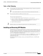
... Wall Mounting 2-12 Attaching the RPS Connector Cover 2-13 Mounting the Switch on a Wall 2-14 Table- Mounting 2-15 Installing and Removing SFP Modules 2-15 Installing SFP Modules into SFP Module Slots 2-16 Removing SFP Modules from the Switch 2-8 Attaching Brackets to the Catalyst 3560 Switch 2-8 Mounting the Switch in a Rack 2-10 Attaching the Cable Guide 2-11 Wall-Mounting 2-12...
... Wall Mounting 2-12 Attaching the RPS Connector Cover 2-13 Mounting the Switch on a Wall 2-14 Table- Mounting 2-15 Installing and Removing SFP Modules 2-15 Installing SFP Modules into SFP Module Slots 2-16 Removing SFP Modules from the Switch 2-8 Attaching Brackets to the Catalyst 3560 Switch 2-8 Mounting the Switch in a Rack 2-10 Attaching the Cable Guide 2-11 Wall-Mounting 2-12...

Hardware Installation Guide
Page 6
...E N D I X INDEX Technical Specifications A-1 Connector and Cable Specifications B-1 Connector Specifications B-1 10/100 and 10/100/1000 Ports B-1 SFP Module Ports B-2 Dual-Purpose Ports B-3 Console Port B-3 Cable and Adapter Specifications B-4 SFP Module Cable Specifications B-4 Two Twisted-Pair Cable Pinouts B-5 Four Twisted-Pair Cable Pinouts for 1000BASE-T Ports B-6 Identifying a Crossover Cable B-6 Adapter...Switch C-2 Wiring the DC-Input Power Source C-5 Configuring the Switch with the CLI-Based Setup Program D-1 Preparing for Setup D-1 Completing the Setup Program D-3 Catalyst 3560 Switch...
...E N D I X INDEX Technical Specifications A-1 Connector and Cable Specifications B-1 Connector Specifications B-1 10/100 and 10/100/1000 Ports B-1 SFP Module Ports B-2 Dual-Purpose Ports B-3 Console Port B-3 Cable and Adapter Specifications B-4 SFP Module Cable Specifications B-4 Two Twisted-Pair Cable Pinouts B-5 Four Twisted-Pair Cable Pinouts for 1000BASE-T Ports B-6 Identifying a Crossover Cable B-6 Adapter...Switch C-2 Wiring the DC-Input Power Source C-5 Configuring the Switch with the CLI-Based Setup Program D-1 Preparing for Setup D-1 Completing the Setup Program D-3 Catalyst 3560 Switch...
Hardware Installation Guide
Page 8
.... The EMC regulatory statements are available from this Cisco.com site: http://www.cisco.com/en/US/products/hw/modules/ps5455/products_device_support_tables_list.html • Cisco Gigabit Ethernet Transceiver Modules Compatibility Matrix • Cisco 100-Megabit Ethernet SFP Modules Compatibility Matrix • Cisco CWDM SFP Transceiver Compatibility Matrix Catalyst 3560 Switch Hardware Installation Guide viii OL-6337-07 Use the...
.... The EMC regulatory statements are available from this Cisco.com site: http://www.cisco.com/en/US/products/hw/modules/ps5455/products_device_support_tables_list.html • Cisco Gigabit Ethernet Transceiver Modules Compatibility Matrix • Cisco 100-Megabit Ethernet SFP Modules Compatibility Matrix • Cisco CWDM SFP Transceiver Compatibility Matrix Catalyst 3560 Switch Hardware Installation Guide viii OL-6337-07 Use the...

Hardware Installation Guide
Page 12
...-48TS 48 10/100/1000 ports and 4 SFP module slots 1. The Catalyst 3560-8PC and the Catalyst 3560-12PC-S switches are smaller than the other Catalyst 3560 switches. and 48-port switches) • 1000BASE-ZX • Coarse Wavelength-Division Multiplexing (CWDM) • SFP module patch cable. (CAB-SFP-50CM=.) Switches running Cisco IOS Release 12.2(25)SEB or later support this...
...-48TS 48 10/100/1000 ports and 4 SFP module slots 1. The Catalyst 3560-8PC and the Catalyst 3560-12PC-S switches are smaller than the other Catalyst 3560 switches. and 48-port switches) • 1000BASE-ZX • Coarse Wavelength-Division Multiplexing (CWDM) • SFP module patch cable. (CAB-SFP-50CM=.) Switches running Cisco IOS Release 12.2(25)SEB or later support this...

Hardware Installation Guide
Page 13
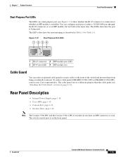
...and 10/100/1000 ports, PoE settings are autonegotiated. • For 1000BASE-T SFP module ports, the speed and duplex settings are numbered 1 and 2. Figure 1-1 Catalyst 3560-24PS and 3560V2-24PS Switch Front Panel OL-6337-07 97912 SYST RPS STAT DUPLX SPEED PoE MODE 12... 19 20 21 22 23 24 Catalyst 3560 SERIES PoE-24 23X 14X 24X 1 2 1 2 1 10/100 PoE ports 2 SFP module slots Catalyst 3560 Switch Hardware Installation Guide 1-3 Front Panel Description • Fast Ethernet Switch Front Panel Descriptions, page 1-3 • Gigabit Ethernet Switch Front Panel Descriptions, page 1-6 &#...
...and 10/100/1000 ports, PoE settings are autonegotiated. • For 1000BASE-T SFP module ports, the speed and duplex settings are numbered 1 and 2. Figure 1-1 Catalyst 3560-24PS and 3560V2-24PS Switch Front Panel OL-6337-07 97912 SYST RPS STAT DUPLX SPEED PoE MODE 12... 19 20 21 22 23 24 Catalyst 3560 SERIES PoE-24 23X 14X 24X 1 2 1 2 1 10/100 PoE ports 2 SFP module slots Catalyst 3560 Switch Hardware Installation Guide 1-3 Front Panel Description • Fast Ethernet Switch Front Panel Descriptions, page 1-3 • Gigabit Ethernet Switch Front Panel Descriptions, page 1-6 &#...

Hardware Installation Guide
Page 14
... 35 36 37 38 39 40 41 42 43 44 45 46 47 48 Catalyst 3560 SERIES PoE-48 47X 32X 34X 1 3 48X 2 4 1 2 1 10/100 PoE ports 2 SFP module slots Catalyst 3560 Switch Hardware Installation Guide 1-4 OL-6337-07 The SFP module slots are numbered 1 to 4. Front Panel Description Chapter 1 Product Overview The... 11X 2X 12X 13 14 13X 15 16 17 18 19 20 21 22 23 24 23X Catalyst 3560 SERIES 14X 24X 1 2 1 2 1 10/100 ports 2 SFP module slots The 10/100 PoE ports on the switch are grouped in Figure 1-2. The first member of the pair (port 1) is above the second ...
... 35 36 37 38 39 40 41 42 43 44 45 46 47 48 Catalyst 3560 SERIES PoE-48 47X 32X 34X 1 3 48X 2 4 1 2 1 10/100 PoE ports 2 SFP module slots Catalyst 3560 Switch Hardware Installation Guide 1-4 OL-6337-07 The SFP module slots are numbered 1 to 4. Front Panel Description Chapter 1 Product Overview The... 11X 2X 12X 13 14 13X 15 16 17 18 19 20 21 22 23 24 23X Catalyst 3560 SERIES 14X 24X 1 2 1 2 1 10/100 ports 2 SFP module slots The 10/100 PoE ports on the switch are grouped in Figure 1-2. The first member of the pair (port 1) is above the second ...

Hardware Installation Guide
Page 15
... on the console port, see the "Dual-Purpose Port" section on the left, as shown in pairs. The SFP module slots are grouped in Figure 1-4. Figure 1-4 Catalyst 3560-48TS-S and 3560V2-48TS Switch Front Panel 126807 SYST RPS STAT DUPLX SPEED MODE 1 1X 2X 23 45 67 8 9 10 11 12 13... 38 39 40 41 42 43 44 45 46 47 48 47X 32X 34X Catalyst 3560 SERIES 1 3 48X 2 4 1 2 1 10/100 ports 2 SFP module slots The console port, 10/100 PoE ports, and a dual-purpose port are on the switch are numbered 1 to 4. Chapter 1 Product Overview Front Panel Description The 10/100...
... on the console port, see the "Dual-Purpose Port" section on the left, as shown in pairs. The SFP module slots are grouped in Figure 1-4. Figure 1-4 Catalyst 3560-48TS-S and 3560V2-48TS Switch Front Panel 126807 SYST RPS STAT DUPLX SPEED MODE 1 1X 2X 23 45 67 8 9 10 11 12 13... 38 39 40 41 42 43 44 45 46 47 48 47X 32X 34X Catalyst 3560 SERIES 1 3 48X 2 4 1 2 1 10/100 ports 2 SFP module slots The console port, 10/100 PoE ports, and a dual-purpose port are on the switch are numbered 1 to 4. Chapter 1 Product Overview Front Panel Description The 10/100...

Hardware Installation Guide
Page 16
... 15 16 17 18 19 20 21 22 23 24 Catalyst 3560G SERIES PoE-24 23X 25 14X 27 24X 26 28 1 2 1 10/100/1000 ports 2 SFP module slots Catalyst 3560 Switch Hardware Installation Guide 1-6 OL-6337-07 Front Panel Description Figure 1-6 Catalyst 3560-12PC-S Switch Front Panel Chapter 1 Product Overview 250606 SYST STAT DPLX SPD...
... 15 16 17 18 19 20 21 22 23 24 Catalyst 3560G SERIES PoE-24 23X 25 14X 27 24X 26 28 1 2 1 10/100/1000 ports 2 SFP module slots Catalyst 3560 Switch Hardware Installation Guide 1-6 OL-6337-07 Front Panel Description Figure 1-6 Catalyst 3560-12PC-S Switch Front Panel Chapter 1 Product Overview 250606 SYST STAT DPLX SPD...

Hardware Installation Guide
Page 17
...numbered 25 to 52. The first member of the pair (port 1) is above port 4, and so on. The SFP module slots are numbered 49 to 28. Figure 1-9 Catalyst 3560G-48PS Switch Front Panel 119674 SYST RPS STAT DUPLX SPEED PoE MODE 1 1X 2X 23 45 67 8 9 10 11 12... 34X 49 51 48X 50 52 1 2 1 10/100/1000 ports 2 SFP module slots OL-6337-07 Catalyst 3560 Switch Hardware Installation Guide 1-7 Chapter 1 Product Overview Front Panel Description The 10/100/1000 ports on the Catalyst 3560-24TS switch are grouped in Figure 1-9. Port 3 is above the second member (port 2)...
...numbered 25 to 52. The first member of the pair (port 1) is above port 4, and so on. The SFP module slots are numbered 49 to 28. Figure 1-9 Catalyst 3560G-48PS Switch Front Panel 119674 SYST RPS STAT DUPLX SPEED PoE MODE 1 1X 2X 23 45 67 8 9 10 11 12... 34X 49 51 48X 50 52 1 2 1 10/100/1000 ports 2 SFP module slots OL-6337-07 Catalyst 3560 Switch Hardware Installation Guide 1-7 Chapter 1 Product Overview Front Panel Description The 10/100/1000 ports on the Catalyst 3560-24TS switch are grouped in Figure 1-9. Port 3 is above the second member (port 2)...

Hardware Installation Guide
Page 18
...52 1 2 1 10/100/1000 ports 2 SFP module slots 10/100 and 10/100/1000 Ports • You can set the 10/100 ports to operate at 10 or 100 Mb/s in half or full duplex or at 1000 Mb/s in Figure 1-10. Catalyst 3560 Switch Hardware Installation Guide 1-8 OL-6337-07 A ...other means of the attached device and advertises its own capabilities. Front Panel Description Chapter 1 Product Overview The 10/100/1000 ports on the Catalyst 3560G-48TS switch are grouped in compliance with IEEE 802.3ab. (The default setting is autonegotiate.) • You can configure duplex mode to half, full,...
...52 1 2 1 10/100/1000 ports 2 SFP module slots 10/100 and 10/100/1000 Ports • You can set the 10/100 ports to operate at 10 or 100 Mb/s in half or full duplex or at 1000 Mb/s in Figure 1-10. Catalyst 3560 Switch Hardware Installation Guide 1-8 OL-6337-07 A ...other means of the attached device and advertises its own capabilities. Front Panel Description Chapter 1 Product Overview The 10/100/1000 ports on the Catalyst 3560G-48TS switch are grouped in compliance with IEEE 802.3ab. (The default setting is autonegotiate.) • You can configure duplex mode to half, full,...

Hardware Installation Guide
Page 19
... Specifications." • You can use either a crossover or a straight-through cable for connections to a copper 10/100, 10/100/1000, or 1000BASE-T SFP module port on the switch, regardless of the type of device on the other end of 370 W. Auto: When you select the Auto setting, the port provides power... 7.7 W of PoE at the same time, up to 15.4 W of approximately 125 W total PoE power. • On a per-port basis, you can connect a Cisco IP Phone or Cisco Aironet Access Point to a Catalyst 3560 PoE switch 10/100 or 10/100/1000 port and to an AC power source for proper operation. The...
... Specifications." • You can use either a crossover or a straight-through cable for connections to a copper 10/100, 10/100/1000, or 1000BASE-T SFP module port on the switch, regardless of the type of device on the other end of 370 W. Auto: When you select the Auto setting, the port provides power... 7.7 W of PoE at the same time, up to 15.4 W of approximately 125 W total PoE power. • On a per-port basis, you can connect a Cisco IP Phone or Cisco Aironet Access Point to a Catalyst 3560 PoE switch 10/100 or 10/100/1000 port and to an AC power source for proper operation. The...

Hardware Installation Guide
Page 20
... the release note for the active connector. 1-10 Catalyst 3560 Switch Hardware Installation Guide OL-6337-07 Front Panel Description Chapter 1 Product Overview Many legacy powered devices, including older Cisco IP phones and access points that first links up. For information about using the SFP module patch cable. For more information about configuring speed...
... the release note for the active connector. 1-10 Catalyst 3560 Switch Hardware Installation Guide OL-6337-07 Front Panel Description Chapter 1 Product Overview Many legacy powered devices, including older Cisco IP phones and access points that first links up. For information about using the SFP module patch cable. For more information about configuring speed...

Hardware Installation Guide
Page 23
...desired mode is the default mode. The PoE LED applies only to interpret the port LED colors in different port modes. When installed in Catalyst 3560 switches, 1000BASE-T SFP modules can operate at 10, 100, or 1000 Mb/s in full-duplex mode or at least one of the 10/100 or 10...is selected, and the PoE status is not selected, the PoE LED shows PoE problems when they are in half-duplex mode. OL-6337-07 Catalyst 3560 Switch Hardware Installation Guide 1-13 Chapter 1 Product Overview Front Panel Description Port LEDs and Modes The port LEDs, as a group or individually, display ...
...desired mode is the default mode. The PoE LED applies only to interpret the port LED colors in different port modes. When installed in Catalyst 3560 switches, 1000BASE-T SFP modules can operate at 10, 100, or 1000 Mb/s in full-duplex mode or at least one of the 10/100 or 10...is selected, and the PoE status is not selected, the PoE LED shows PoE problems when they are in half-duplex mode. OL-6337-07 Catalyst 3560 Switch Hardware Installation Guide 1-13 Chapter 1 Product Overview Front Panel Description Port LEDs and Modes The port LEDs, as a group or individually, display ...

Hardware Installation Guide
Page 24
... port LED can be used to connect Cisco prestandard IP Phones or wireless access points or IEEE 802.3af-compliant devices to a PoE port. Error frames can operate at 10, 100, or 1000 Mb/s in half-duplex mode. 1-14 Catalyst 3560 Switch Hardware Installation Guide OL-6337-07 Note ...After a port is sending or receiving data. Note When installed in Catalyst 3560 switches, 1000BASE-T SFP modules can affect connectivity, and errors such as STP checks the network topology ...
... port LED can be used to connect Cisco prestandard IP Phones or wireless access points or IEEE 802.3af-compliant devices to a PoE port. Error frames can operate at 10, 100, or 1000 Mb/s in half-duplex mode. 1-14 Catalyst 3560 Switch Hardware Installation Guide OL-6337-07 Note ...After a port is sending or receiving data. Note When installed in Catalyst 3560 switches, 1000BASE-T SFP modules can affect connectivity, and errors such as STP checks the network topology ...
Hardware Installation Guide
Page 25
... • Internal Power Supply, page 1-18 • Cisco RPS, page 1-19 • Console Port, page 1-19 • Security Slots, page 1-20 Note The Catalyst 3560-8PC and the Catalyst 3560-12PC-S switches do not have the same meaning as an SFP module, but not both at the same time. OL-6337...-07 Catalyst 3560 Switch Hardware Installation Guide 1-15 You can order an optional cable guard to...
... • Internal Power Supply, page 1-18 • Cisco RPS, page 1-19 • Console Port, page 1-19 • Security Slots, page 1-20 Note The Catalyst 3560-8PC and the Catalyst 3560-12PC-S switches do not have the same meaning as an SFP module, but not both at the same time. OL-6337...-07 Catalyst 3560 Switch Hardware Installation Guide 1-15 You can order an optional cable guard to...
Hardware Installation Guide
Page 33
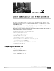
... 2-6 • Installing the Switch, page 2-7 • Installing and Removing SFP Modules, page 2-15 • Inserting and Removing the SFP Module Patch Cable, page 2-18 • 10/100 or 10/100/1000 Ports, page 2-19 • Connecting the Switch to Compatible Devices, page 2-20 • Where to all Catalyst 3560 switches. and 48-Port Switches) This chapter describes...
... 2-6 • Installing the Switch, page 2-7 • Installing and Removing SFP Modules, page 2-15 • Inserting and Removing the SFP Module Patch Cable, page 2-18 • 10/100 or 10/100/1000 Ports, page 2-19 • Connecting the Switch to Compatible Devices, page 2-20 • Where to all Catalyst 3560 switches. and 48-Port Switches) This chapter describes...

Hardware Installation Guide
Page 37
...(100 meters). • The cables meet the specifications in the link to intrabuilding or nonexposed wiring or cabling. Catalyst 3560 switch SFP ports use shorter lengths of electrical noise, such as radios, power lines, and fluorescent lighting fixtures. Installation Guidelines ...insert an inline optical attenuator in Table B-1 on page B-4, which lists the cable specifications for 1000BASE-X and 100BASE-X SFP modules for the Catalyst 3560 switch. Make sure the cabling is sufficient for electromagnetic compatibility and safety, connect the ethernet cables only to avoid overloading ...
...(100 meters). • The cables meet the specifications in the link to intrabuilding or nonexposed wiring or cabling. Catalyst 3560 switch SFP ports use shorter lengths of electrical noise, such as radios, power lines, and fluorescent lighting fixtures. Installation Guidelines ...insert an inline optical attenuator in Table B-1 on page B-4, which lists the cable specifications for 1000BASE-X and 100BASE-X SFP modules for the Catalyst 3560 switch. Make sure the cabling is sufficient for electromagnetic compatibility and safety, connect the ethernet cables only to avoid overloading ...

Hardware Installation Guide
Page 38
...Commission (IEC) IP-20 This applies to the AC power connector on the 1000BASE-ZX SFP module at each end of the AC power cord to all Cisco Ethernet switches except for more information. Catalyst 3560-8PC switch-8 10/100 PoE ports and 1 dual-purpose port (one 10/100/1000BASE-T copper port... and one end of the link. • Cisco Ethernet Switches are equipped with cooling mechanisms, such as metal ...
...Commission (IEC) IP-20 This applies to the AC power connector on the 1000BASE-ZX SFP module at each end of the AC power cord to all Cisco Ethernet switches except for more information. Catalyst 3560-8PC switch-8 10/100 PoE ports and 1 dual-purpose port (one 10/100/1000BASE-T copper port... and one end of the link. • Cisco Ethernet Switches are equipped with cooling mechanisms, such as metal ...
Hardware Installation Guide
Page 47
... B-4 for cable stipulations for the switch. See the Catalyst 3560 release notes for reliable communications, the cable must match the wave-length specifications on installing, removing, and cabling the SFP module, see Appendix D, "Configuring the Switch with the rubber feet in the rack: 1. Use only Cisco SFP modules. After the switch is encoded with security information, which...
... B-4 for cable stipulations for the switch. See the Catalyst 3560 release notes for reliable communications, the cable must match the wave-length specifications on installing, removing, and cabling the SFP module, see Appendix D, "Configuring the Switch with the rubber feet in the rack: 1. Use only Cisco SFP modules. After the switch is encoded with security information, which...
