
Hardware Installation Guide
Page 12
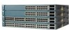
... and 2 SFP module slots Catalyst 3560V2-48PS 48 10/100 PoE ports and 4 SFP module slots Catalyst 3560V2-48TS 48 10/100 ports and 4 SFP module slots Catalyst 3560V2-24TS-SD 24 10/100 PoE ports and 2 SFP module slots (DC power) Catalyst 3560-8PC1 8 10/100...8226; 1000BASE-T (only Catalyst 3560 24- The Catalyst 3560-8PC and the Catalyst 3560-12PC-S switches are smaller than the other Catalyst 3560 switches. and 48-port switches) • 1000BASE-ZX • Coarse Wavelength-Division Multiplexing (CWDM) • SFP module patch cable. (CAB-SFP-50CM=.) Switches running Cisco IOS Release 12.2(25...
... and 2 SFP module slots Catalyst 3560V2-48PS 48 10/100 PoE ports and 4 SFP module slots Catalyst 3560V2-48TS 48 10/100 ports and 4 SFP module slots Catalyst 3560V2-24TS-SD 24 10/100 PoE ports and 2 SFP module slots (DC power) Catalyst 3560-8PC1 8 10/100...8226; 1000BASE-T (only Catalyst 3560 24- The Catalyst 3560-8PC and the Catalyst 3560-12PC-S switches are smaller than the other Catalyst 3560 switches. and 48-port switches) • 1000BASE-ZX • Coarse Wavelength-Division Multiplexing (CWDM) • SFP module patch cable. (CAB-SFP-50CM=.) Switches running Cisco IOS Release 12.2(25...

Hardware Installation Guide
Page 13
...-24TS-S, 3560V2-24TS, and 3560V2-24TS-SD Switch Front Panel, Figure 1-2 on page 1-4 • Catalyst 3560-48PS and 3560V2-48PS Switch Front Panel, Figure 1-3 on page 1-4 • Catalyst 3560-48TS-S and 3560V2-48TS Switch Front Panel, Figure 1-4 on page 1-5 • Catalyst 3560-8PC Switch Front Panel, Figure 1-5 on page 1-5 • Catalyst 3560-12PC-S Switch Front Panel, Figure 1-6 on page 1-6 The...
...-24TS-S, 3560V2-24TS, and 3560V2-24TS-SD Switch Front Panel, Figure 1-2 on page 1-4 • Catalyst 3560-48PS and 3560V2-48PS Switch Front Panel, Figure 1-3 on page 1-4 • Catalyst 3560-48TS-S and 3560V2-48TS Switch Front Panel, Figure 1-4 on page 1-5 • Catalyst 3560-8PC Switch Front Panel, Figure 1-5 on page 1-5 • Catalyst 3560-12PC-S Switch Front Panel, Figure 1-6 on page 1-6 The...

Hardware Installation Guide
Page 14
... are grouped in pairs. Figure 1-2 Catalyst 3560-24TS-S, 3560V2-24TS, and 3560V2-24TS-SD Switch Front Panel 126808 SYST RPS STAT DUPLX SPEED MODE 12 1X 34 56 78 9 10 11 12 11X 2X 12X 13 14 13X 15 16 17 18 19 20 21 22 23 24 23X Catalyst 3560 SERIES 14X 24X... 31X 33X 34 35 36 37 38 39 40 41 42 43 44 45 46 47 48 Catalyst 3560 SERIES PoE-48 47X 32X 34X 1 3 48X 2 4 1 2 1 10/100 PoE ports 2 SFP module slots Catalyst 3560 Switch Hardware Installation Guide 1-4 OL-6337-07 The first member of the pair (port 1) is above the second...
... are grouped in pairs. Figure 1-2 Catalyst 3560-24TS-S, 3560V2-24TS, and 3560V2-24TS-SD Switch Front Panel 126808 SYST RPS STAT DUPLX SPEED MODE 12 1X 34 56 78 9 10 11 12 11X 2X 12X 13 14 13X 15 16 17 18 19 20 21 22 23 24 23X Catalyst 3560 SERIES 14X 24X... 31X 33X 34 35 36 37 38 39 40 41 42 43 44 45 46 47 48 Catalyst 3560 SERIES PoE-48 47X 32X 34X 1 3 48X 2 4 1 2 1 10/100 PoE ports 2 SFP module slots Catalyst 3560 Switch Hardware Installation Guide 1-4 OL-6337-07 The first member of the pair (port 1) is above the second...
Hardware Installation Guide
Page 27
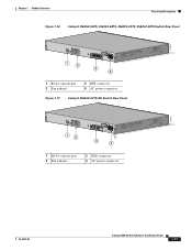
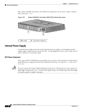
Chapter 1 Product Overview Rear Panel Description Figure 1-16 Catalyst 3560V2-24PS, 3560V2-48PS, 3560V2-24TS, 3560V2-48TS Switch Rear Panel 274670 CONSOLE 1 2 3 4 1 RJ-45 console port 2 Fan exhaust 3 RPS connector 4 AC power connector Figure 1-17 Catalyst 3560V2-24TS-SD Switch Rear Panel 274671 CONSOLE 12 3 4 1 RJ-45 console port 2 Fan exhaust 3 RPS connector 4 DC power connector OL-6337-07 Catalyst 3560 Switch Hardware Installation Guide 1-17
Chapter 1 Product Overview Rear Panel Description Figure 1-16 Catalyst 3560V2-24PS, 3560V2-48PS, 3560V2-24TS, 3560V2-48TS Switch Rear Panel 274670 CONSOLE 1 2 3 4 1 RJ-45 console port 2 Fan exhaust 3 RPS connector 4 AC power connector Figure 1-17 Catalyst 3560V2-24TS-SD Switch Rear Panel 274671 CONSOLE 12 3 4 1 RJ-45 console port 2 Fan exhaust 3 RPS connector 4 DC power connector OL-6337-07 Catalyst 3560 Switch Hardware Installation Guide 1-17
Hardware Installation Guide
Page 28
... voltage is an autoranging unit that are diode-OR-ed into a single power block. DC Power Connector The Catalyst 3560V2-24TS-SD has an internal DC-power converter. Caution You must connect the Catalyst 3560V2-24TS-SD switch only to a DC-input power source that has an input supply voltage from -36 to DC Power...
... voltage is an autoranging unit that are diode-OR-ed into a single power block. DC Power Connector The Catalyst 3560V2-24TS-SD has an internal DC-power converter. Caution You must connect the Catalyst 3560V2-24TS-SD switch only to a DC-input power source that has an input supply voltage from -36 to DC Power...

Hardware Installation Guide
Page 29
...Catalyst 3560V2-24TS-SD switch, the switch is a redundant power system that supports six network devices and provides power to one or two failed switches at a time. You can connect the switch to either of these Cisco redundant power systems (RPS) to provide backup power if the switch power supply fails: • "Cisco...the supplied RJ-45-to the switch. The maximum output power depends on page B-1. OL-6337-07 Catalyst 3560 Switch Hardware Installation Guide 1-19 The Cisco RPS 2300 has two output levels: -52 V and 12 V. Cisco RPS 675 The Cisco 675 RPS is not Network Equipment ...
...Catalyst 3560V2-24TS-SD switch, the switch is a redundant power system that supports six network devices and provides power to one or two failed switches at a time. You can connect the switch to either of these Cisco redundant power systems (RPS) to provide backup power if the switch power supply fails: • "Cisco...the supplied RJ-45-to the switch. The maximum output power depends on page B-1. OL-6337-07 Catalyst 3560 Switch Hardware Installation Guide 1-19 The Cisco RPS 2300 has two output levels: -52 V and 12 V. Cisco RPS 675 The Cisco 675 RPS is not Network Equipment ...
Hardware Installation Guide
Page 85
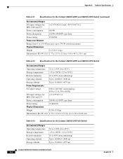
...; Table A-11 on page A-5, Specifications for the Catalyst 3560V2-48PS and 3560V2-24PS Switch • Table A-12 on page A-6, Specifications for the Catalyst 3560V2-48TS and 3560V2-24TS Switch • Table A-13 on page A-6, Specifications for the Catalyst 3560V2-24TS-SD Switch Table A-1 Environmental Ranges for all Catalyst 3560 Switches Operating temperature Storage temperature Relative humidity Operating altitude Storage...
...; Table A-11 on page A-5, Specifications for the Catalyst 3560V2-48PS and 3560V2-24PS Switch • Table A-12 on page A-6, Specifications for the Catalyst 3560V2-48TS and 3560V2-24TS Switch • Table A-13 on page A-6, Specifications for the Catalyst 3560V2-24TS-SD Switch Table A-1 Environmental Ranges for all Catalyst 3560 Switches Operating temperature Storage temperature Relative humidity Operating altitude Storage...
Hardware Installation Guide
Page 90
... Power rating 0.180 kVA Physical Dimensions Weight 8.5 lb (3.9 kg) Dimensions (H x W x D) 1.73 x 11.81 x 17.5 in. (4.4 x 30 x 44.45 cm) Table A-13 Specifications for the Catalyst 3560V2-24TS-SD Switch Environmental Ranges Operating temperature Storage temperature Relative humidity Operating altitude Storage altitude 32 to 113°F (0 to 45°C) -13 to 158°F (-25...
... Power rating 0.180 kVA Physical Dimensions Weight 8.5 lb (3.9 kg) Dimensions (H x W x D) 1.73 x 11.81 x 17.5 in. (4.4 x 30 x 44.45 cm) Table A-13 Specifications for the Catalyst 3560V2-24TS-SD Switch Environmental Ranges Operating temperature Storage temperature Relative humidity Operating altitude Storage altitude 32 to 113°F (0 to 45°C) -13 to 158°F (-25...
Hardware Installation Guide
Page 91
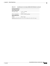
Appendix A Technical Specifications Table A-13 Specifications for the Catalyst 3560V2-24TS-SD Switch (continued) Environmental Ranges Power Requirements DC input voltage -36 to -72 VDC 3 to 1.5 A Power consumption 94 W, 321 BTUs per hour Physical Dimensions Weight 9 lb (4.1 kg) Dimensions (H x W x D) 1.73 x 17.5 x 11.8 in. (4.4 x 44.5 x 30.1 cm) OL-6337-07 Catalyst 3560 Switch Hardware Installation Guide A-7
Appendix A Technical Specifications Table A-13 Specifications for the Catalyst 3560V2-24TS-SD Switch (continued) Environmental Ranges Power Requirements DC input voltage -36 to -72 VDC 3 to 1.5 A Power consumption 94 W, 321 BTUs per hour Physical Dimensions Weight 9 lb (4.1 kg) Dimensions (H x W x D) 1.73 x 17.5 x 11.8 in. (4.4 x 44.5 x 30.1 cm) OL-6337-07 Catalyst 3560 Switch Hardware Installation Guide A-7
Hardware Installation Guide
Page 101
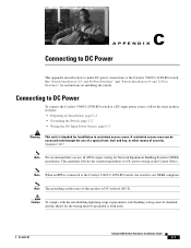
...24- A restricted access area can be grounded at both ends. Note When an RPS is connected to the Catalyst 3560V2-24TS-SD switch. C A P P E N D I ). and 12-Port Switches)" for Network Equipment Building Systems (NEBS) installation. Statement 1017 Note We recommend that you use of a ...Power This appendix describes how to make DC power connections to the Catalyst 3560V2-24TS-SD switch, the switch is intended for installation in the Central Office. Connecting to DC Power To connect the Catalyst 3560V2-24TS-SD switch to a DC-input power source, follow the steps in these ...
...24- A restricted access area can be grounded at both ends. Note When an RPS is connected to the Catalyst 3560V2-24TS-SD switch. C A P P E N D I ). and 12-Port Switches)" for Network Equipment Building Systems (NEBS) installation. Statement 1017 Note We recommend that you use of a ...Power This appendix describes how to make DC power connections to the Catalyst 3560V2-24TS-SD switch, the switch is intended for installation in the Central Office. Connecting to DC Power To connect the Catalyst 3560V2-24TS-SD switch to a DC-input power source, follow the steps in these ...
Hardware Installation Guide
Page 102
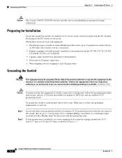
... Installation Guide C-2 OL-6337-07 Obtain these steps. Connecting to DC Power Appendix C Connecting to DC Power Caution The Catalyst 3560V2-24TS-SD switch is reliably connected to earth ground, follow the grounding procedure instructions, and use a wire stripping tool to strip the 6-gauge ...ground wire to 0.5 inch (12.7 mm) ± 0.02 inch (0.5 mm), as shown in the absence of the switch. (See Figure C-3 for location.) Use a ...
... Installation Guide C-2 OL-6337-07 Obtain these steps. Connecting to DC Power Appendix C Connecting to DC Power Caution The Catalyst 3560V2-24TS-SD switch is reliably connected to earth ground, follow the grounding procedure instructions, and use a wire stripping tool to strip the 6-gauge ...ground wire to 0.5 inch (12.7 mm) ± 0.02 inch (0.5 mm), as shown in the absence of the switch. (See Figure C-3 for location.) Use a ...
Hardware Installation Guide
Page 105
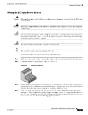
...in Figure C-6. Step 2 Locate and remove the terminal block plug (see Figure C-5). OL-6337-07 Catalyst 3560 Switch Hardware Installation Guide C-5 Caution The switch must connect the Catalyst 3560V2-24TS-SD switch only to a DC-input power source that power is positive to positive and negative to negative for... installation. Statement 1003 Warning Only trained and qualified personnel should be allowed to install, replace, or service this range, the switch might not operate properly or might be installed with all applicable codes. The wiring sequence is removed from the DC circuit. ...
...in Figure C-6. Step 2 Locate and remove the terminal block plug (see Figure C-5). OL-6337-07 Catalyst 3560 Switch Hardware Installation Guide C-5 Caution The switch must connect the Catalyst 3560V2-24TS-SD switch only to a DC-input power source that power is positive to positive and negative to negative for... installation. Statement 1003 Warning Only trained and qualified personnel should be allowed to install, replace, or service this range, the switch might not operate properly or might be installed with all applicable codes. The wiring sequence is removed from the DC circuit. ...