
Hardware Installation Guide
Page 12
... • 1000BASE-LX • 1000BASE-SX • 1000BASE-T (only Catalyst 3560 24- and 48-port switches) • 1000BASE-ZX • Coarse Wavelength-Division Multiplexing (CWDM) • SFP module patch cable. (CAB-SFP-50CM=.) Switches running Cisco IOS Release 12.2(25)SEB or later support this patch cable. They can...100 ports and 2 SFP module slots Catalyst 3560V2-48PS 48 10/100 PoE ports and 4 SFP module slots Catalyst 3560V2-48TS 48 10/100 ports and 4 SFP module slots Catalyst 3560V2-24TS-SD 24 10/100 PoE ports and 2 SFP module slots (DC power) Catalyst 3560-8PC1 8 10/100 PoE ports...
... • 1000BASE-LX • 1000BASE-SX • 1000BASE-T (only Catalyst 3560 24- and 48-port switches) • 1000BASE-ZX • Coarse Wavelength-Division Multiplexing (CWDM) • SFP module patch cable. (CAB-SFP-50CM=.) Switches running Cisco IOS Release 12.2(25)SEB or later support this patch cable. They can...100 ports and 2 SFP module slots Catalyst 3560V2-48PS 48 10/100 PoE ports and 4 SFP module slots Catalyst 3560V2-48TS 48 10/100 ports and 4 SFP module slots Catalyst 3560V2-24TS-SD 24 10/100 PoE ports and 2 SFP module slots (DC power) Catalyst 3560-8PC1 8 10/100 PoE ports...

Hardware Installation Guide
Page 13
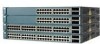
...-24TS-S, 3560V2-24TS, and 3560V2-24TS-SD Switch Front Panel, Figure 1-2 on page 1-4 • Catalyst 3560-48PS and 3560V2-48PS Switch Front Panel, Figure 1-3 on page 1-4 • Catalyst 3560-48TS-S and 3560V2-48TS Switch Front Panel, Figure 1-4 on page 1-5 • Catalyst 3560-8PC Switch Front Panel, Figure 1-5 on page 1-5 • Catalyst 3560-12PC-S Switch Front Panel, Figure 1-6 on page 1-6 The...
...-24TS-S, 3560V2-24TS, and 3560V2-24TS-SD Switch Front Panel, Figure 1-2 on page 1-4 • Catalyst 3560-48PS and 3560V2-48PS Switch Front Panel, Figure 1-3 on page 1-4 • Catalyst 3560-48TS-S and 3560V2-48TS Switch Front Panel, Figure 1-4 on page 1-5 • Catalyst 3560-8PC Switch Front Panel, Figure 1-5 on page 1-5 • Catalyst 3560-12PC-S Switch Front Panel, Figure 1-6 on page 1-6 The...

Hardware Installation Guide
Page 14
... PoE-48 47X 32X 34X 1 3 48X 2 4 1 2 1 10/100 PoE ports 2 SFP module slots Catalyst 3560 Switch Hardware Installation Guide 1-4 OL-6337-07 Figure 1-2 Catalyst 3560-24TS-S, 3560V2-24TS, and 3560V2-24TS-SD Switch Front Panel 126808 SYST RPS STAT DUPLX SPEED MODE 12 1X 34 56 78 9 10 11 12 11X 2X 12X ...13 14 13X 15 16 17 18 19 20 21 22 23 24 23X Catalyst 3560 SERIES 14X 24X 1 2 1 2...
... PoE-48 47X 32X 34X 1 3 48X 2 4 1 2 1 10/100 PoE ports 2 SFP module slots Catalyst 3560 Switch Hardware Installation Guide 1-4 OL-6337-07 Figure 1-2 Catalyst 3560-24TS-S, 3560V2-24TS, and 3560V2-24TS-SD Switch Front Panel 126808 SYST RPS STAT DUPLX SPEED MODE 12 1X 34 56 78 9 10 11 12 11X 2X 12X ...13 14 13X 15 16 17 18 19 20 21 22 23 24 23X Catalyst 3560 SERIES 14X 24X 1 2 1 2...
Hardware Installation Guide
Page 27
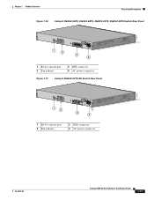
Chapter 1 Product Overview Rear Panel Description Figure 1-16 Catalyst 3560V2-24PS, 3560V2-48PS, 3560V2-24TS, 3560V2-48TS Switch Rear Panel 274670 CONSOLE 1 2 3 4 1 RJ-45 console port 2 Fan exhaust 3 RPS connector 4 AC power connector Figure 1-17 Catalyst 3560V2-24TS-SD Switch Rear Panel 274671 CONSOLE 12 3 4 1 RJ-45 console port 2 Fan exhaust 3 RPS connector 4 DC power connector OL-6337-07 Catalyst 3560 Switch Hardware Installation Guide 1-17
Chapter 1 Product Overview Rear Panel Description Figure 1-16 Catalyst 3560V2-24PS, 3560V2-48PS, 3560V2-24TS, 3560V2-48TS Switch Rear Panel 274670 CONSOLE 1 2 3 4 1 RJ-45 console port 2 Fan exhaust 3 RPS connector 4 AC power connector Figure 1-17 Catalyst 3560V2-24TS-SD Switch Rear Panel 274671 CONSOLE 12 3 4 1 RJ-45 console port 2 Fan exhaust 3 RPS connector 4 DC power connector OL-6337-07 Catalyst 3560 Switch Hardware Installation Guide 1-17
Hardware Installation Guide
Page 28
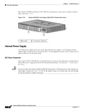
... an AC power outlet. Caution You must connect the Catalyst 3560V2-24TS-SD switch only to -72 VDC. Use the supplied AC power cord to connect the AC power connector to DC Power." DC Power Connector The Catalyst 3560V2-24TS-SD has an internal DC-power converter. The internal power ...supply is not in this range, the switch might not operate properly or might be damaged. 1-18 Catalyst 3560 Switch Hardware Installation Guide OL-6337-07 It has dual...
... an AC power outlet. Caution You must connect the Catalyst 3560V2-24TS-SD switch only to -72 VDC. Use the supplied AC power cord to connect the AC power connector to DC Power." DC Power Connector The Catalyst 3560V2-24TS-SD has an internal DC-power converter. The internal power ...supply is not in this range, the switch might not operate properly or might be damaged. 1-18 Catalyst 3560 Switch Hardware Installation Guide OL-6337-07 It has dual...

Hardware Installation Guide
Page 29
... Building Systems (NEBS) compliant. Note The Catalyst 3560-8PC and Catalyst 3560-12PC-S switches do not have an RPS connector. For complete information about the Cisco RPS products, including compatibility matrixes listing the supported RPS for each Catalyst 3560 switch, see the "Connector and Cable Specifications" ...connector cable supplied with the RPS to connect the RPS to the Catalyst 3560V2-24TS-SD switch, the switch is 675 W. If you want to connect the switch console port to a terminal, you can connect the switch to either of the console port and the supplied RJ-45-...
... Building Systems (NEBS) compliant. Note The Catalyst 3560-8PC and Catalyst 3560-12PC-S switches do not have an RPS connector. For complete information about the Cisco RPS products, including compatibility matrixes listing the supported RPS for each Catalyst 3560 switch, see the "Connector and Cable Specifications" ...connector cable supplied with the RPS to connect the RPS to the Catalyst 3560V2-24TS-SD switch, the switch is 675 W. If you want to connect the switch console port to a terminal, you can connect the switch to either of the console port and the supplied RJ-45-...
Hardware Installation Guide
Page 85
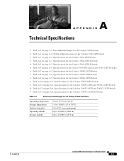
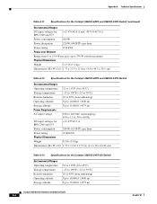
...; Table A-11 on page A-5, Specifications for the Catalyst 3560V2-48PS and 3560V2-24PS Switch • Table A-12 on page A-6, Specifications for the Catalyst 3560V2-48TS and 3560V2-24TS Switch • Table A-13 on page A-6, Specifications for the Catalyst 3560V2-24TS-SD Switch Table A-1 Environmental Ranges for all Catalyst 3560 Switches Operating temperature Storage temperature Relative humidity Operating altitude Storage...
...; Table A-11 on page A-5, Specifications for the Catalyst 3560V2-48PS and 3560V2-24PS Switch • Table A-12 on page A-6, Specifications for the Catalyst 3560V2-48TS and 3560V2-24TS Switch • Table A-13 on page A-6, Specifications for the Catalyst 3560V2-24TS-SD Switch Table A-1 Environmental Ranges for all Catalyst 3560 Switches Operating temperature Storage temperature Relative humidity Operating altitude Storage...
Hardware Installation Guide
Page 90
... Power rating 0.180 kVA Physical Dimensions Weight 8.5 lb (3.9 kg) Dimensions (H x W x D) 1.73 x 11.81 x 17.5 in. (4.4 x 30 x 44.45 cm) Table A-13 Specifications for the Catalyst 3560V2-24TS-SD Switch Environmental Ranges Operating temperature Storage temperature Relative humidity Operating altitude Storage altitude 32 to 113°F (0 to 45°C) -13 to 158°F (-25...
... Power rating 0.180 kVA Physical Dimensions Weight 8.5 lb (3.9 kg) Dimensions (H x W x D) 1.73 x 11.81 x 17.5 in. (4.4 x 30 x 44.45 cm) Table A-13 Specifications for the Catalyst 3560V2-24TS-SD Switch Environmental Ranges Operating temperature Storage temperature Relative humidity Operating altitude Storage altitude 32 to 113°F (0 to 45°C) -13 to 158°F (-25...
Hardware Installation Guide
Page 91
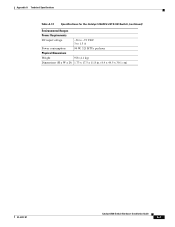
Appendix A Technical Specifications Table A-13 Specifications for the Catalyst 3560V2-24TS-SD Switch (continued) Environmental Ranges Power Requirements DC input voltage -36 to -72 VDC 3 to 1.5 A Power consumption 94 W, 321 BTUs per hour Physical Dimensions Weight 9 lb (4.1 kg) Dimensions (H x W x D) 1.73 x 17.5 x 11.8 in. (4.4 x 44.5 x 30.1 cm) OL-6337-07 Catalyst 3560 Switch Hardware Installation Guide A-7
Appendix A Technical Specifications Table A-13 Specifications for the Catalyst 3560V2-24TS-SD Switch (continued) Environmental Ranges Power Requirements DC input voltage -36 to -72 VDC 3 to 1.5 A Power consumption 94 W, 321 BTUs per hour Physical Dimensions Weight 9 lb (4.1 kg) Dimensions (H x W x D) 1.73 x 17.5 x 11.8 in. (4.4 x 44.5 x 30.1 cm) OL-6337-07 Catalyst 3560 Switch Hardware Installation Guide A-7
Hardware Installation Guide
Page 101
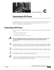
...how to make DC power connections to the Catalyst 3560V2-24TS-SD switch. This guideline follows the standard guidelines for Network Equipment Building Systems (NEBS) installation. OL-6337-07 Catalyst 3560 Switch Hardware Installation Guide C-1 and 48-Port Switches)" and "Switch Installation (8- Note When an RPS is ... wiring for DC power wiring in restricted access areas. Connecting to DC Power To connect the Catalyst 3560V2-24TS-SD switch to the Catalyst 3560V2-24TS-SD switch, the switch is intended for the wiring must be shielded, and the shield for installation in the Central ...
...how to make DC power connections to the Catalyst 3560V2-24TS-SD switch. This guideline follows the standard guidelines for Network Equipment Building Systems (NEBS) installation. OL-6337-07 Catalyst 3560 Switch Hardware Installation Guide C-1 and 48-Port Switches)" and "Switch Installation (8- Note When an RPS is ... wiring for DC power wiring in restricted access areas. Connecting to DC Power To connect the Catalyst 3560V2-24TS-SD switch to the Catalyst 3560V2-24TS-SD switch, the switch is intended for the wiring must be shielded, and the shield for installation in the Central ...
Hardware Installation Guide
Page 102
...number-10-32 ground-lug screws. Set the screws and the ground lug aside. Connecting to DC Power Appendix C Connecting to DC Power Caution The Catalyst 3560V2-24TS-SD switch is suitable only for Installation Locate the ground lug and the two number-10-32 screws on the... switch rear panel and the DC terminal block plug in the DC-switch accessory kit. Catalyst 3560 Switch Hardware Installation Guide C-2 OL-6337-07 Obtain these steps. Statement 1024 Caution To make sure that...
...number-10-32 ground-lug screws. Set the screws and the ground lug aside. Connecting to DC Power Appendix C Connecting to DC Power Caution The Catalyst 3560V2-24TS-SD switch is suitable only for Installation Locate the ground lug and the two number-10-32 screws on the... switch rear panel and the DC terminal block plug in the DC-switch accessory kit. Catalyst 3560 Switch Hardware Installation Guide C-2 OL-6337-07 Obtain these steps. Statement 1024 Caution To make sure that...
Hardware Installation Guide
Page 105
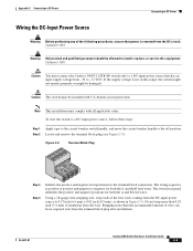
... the A and B feed wires. Note This installation must be damaged. OL-6337-07 Catalyst 3560 Switch Hardware Installation Guide C-5 Statement 1030 Caution You must connect the Catalyst 3560V2-24TS-SD switch only to a DC-input power source that has an input supply voltage from the wire.... Caution The switch must comply with 5 A-branch-circuit protection. Stripping more than the recommended amount of ...
... the A and B feed wires. Note This installation must be damaged. OL-6337-07 Catalyst 3560 Switch Hardware Installation Guide C-5 Statement 1030 Caution You must connect the Catalyst 3560V2-24TS-SD switch only to a DC-input power source that has an input supply voltage from the wire.... Caution The switch must comply with 5 A-branch-circuit protection. Stripping more than the recommended amount of ...