
Installation Guide
Page 6
... 1-31 Large Campus Configuration 1-33 Installing and Starting Up the Switch 2-1 Preparing for Using the Switch 1-25 Small- Contents 2 C H A P T E R LEDs 1-11 System LED 1-14 RPS LED 1-15 Port LEDs and Modes 1-16 Rear-Panel Description 1-21 Power Connectors 1-22 Internal Power Supply Connector 1-23 Cisco RPS Connector 1-23 Console Port 1-24 Management Options 1-24 Network Configuration...
... 1-31 Large Campus Configuration 1-33 Installing and Starting Up the Switch 2-1 Preparing for Using the Switch 1-25 Small- Contents 2 C H A P T E R LEDs 1-11 System LED 1-14 RPS LED 1-15 Port LEDs and Modes 1-16 Rear-Panel Description 1-21 Power Connectors 1-22 Internal Power Supply Connector 1-23 Cisco RPS Connector 1-23 Console Port 1-24 Management Options 1-24 Network Configuration...

Installation Guide
Page 8
Contents A A P P E N D I X B A P P E N D I X C A P P E N D I X Technical Specifications A-1 Connector and Cable Specifications B-1 Connector Specifications B-1 10/100 Ports B-1 1000BaseX Ports B-2 Gigastack Port B-3 Console Port B-3 Cable and Adapter Specifications B-4 Crossover and Straight-Through Cable Pinouts B-4 Rollover Cable and Adapter Pinouts B-5 Identifying a Rollover Cable B-5 Connecting to a PC B-6 Connecting to a Terminal B-7 Translated Safety Warnings C-1 Attaching the Cisco RPS (model PWR600-AC-RPS) C-2 Attaching...
Contents A A P P E N D I X B A P P E N D I X C A P P E N D I X Technical Specifications A-1 Connector and Cable Specifications B-1 Connector Specifications B-1 10/100 Ports B-1 1000BaseX Ports B-2 Gigastack Port B-3 Console Port B-3 Cable and Adapter Specifications B-4 Crossover and Straight-Through Cable Pinouts B-4 Rollover Cable and Adapter Pinouts B-5 Identifying a Rollover Cable B-5 Connecting to a PC B-6 Connecting to a Terminal B-7 Translated Safety Warnings C-1 Attaching the Cisco RPS (model PWR600-AC-RPS) C-2 Attaching...

Installation Guide
Page 12
...• Information you are installing the switch. Appendix A, "Technical Specifications," lists the physical and environmental specifications for installing a switch on a rack, wall, table, or shelf. Appendix B, "Connector and Cable Specifications," describes the connectors, cables, and adapters that might arise ...Troubleshooting," describes how to identify and resolve some of the switch. Chapter 2, "Installing and Starting Up the Switch," contains the procedures for the switches and the regulatory agency approvals. Catalyst 3500 Series XL Hardware Installation Guide xii 78-6456-04 ...
...• Information you are installing the switch. Appendix A, "Technical Specifications," lists the physical and environmental specifications for installing a switch on a rack, wall, table, or shelf. Appendix B, "Connector and Cable Specifications," describes the connectors, cables, and adapters that might arise ...Troubleshooting," describes how to identify and resolve some of the switch. Chapter 2, "Installing and Starting Up the Switch," contains the procedures for the switches and the regulatory agency approvals. Catalyst 3500 Series XL Hardware Installation Guide xii 78-6456-04 ...

Installation Guide
Page 31
... any compatible network device: • 10BaseT-compatible devices such as workstations, Cisco IP Phones, and hubs through standard RJ-45 connectors and Category 3, 4, or 5 cabling 78-6456-04 Catalyst 3500 Series XL Hardware Installation Guide 1-7 Chapter 1 Product Overview Figure 1-5 Catalyst 3524-PWR XL Switch Front-Panel Description 30291 12 1X 34 56 78 MODE SYSTEM...
... any compatible network device: • 10BaseT-compatible devices such as workstations, Cisco IP Phones, and hubs through standard RJ-45 connectors and Category 3, 4, or 5 cabling 78-6456-04 Catalyst 3500 Series XL Hardware Installation Guide 1-7 Chapter 1 Product Overview Figure 1-5 Catalyst 3524-PWR XL Switch Front-Panel Description 30291 12 1X 34 56 78 MODE SYSTEM...

Installation Guide
Page 32
...-connected to the 10/100 ports on the Catalyst 3512, 3524, and 3548 XL switches-must be explicitly set to the following phones: Cisco IP Phone 7960, Cisco IP Phone 7940, and Cisco IP Phone 7910 • Automatically detect if a Cisco IP Phone is a straight-through standard RJ-45 connectors and Category 5 cabling Note Category 5 cable is...
...-connected to the 10/100 ports on the Catalyst 3512, 3524, and 3548 XL switches-must be explicitly set to the following phones: Cisco IP Phone 7960, Cisco IP Phone 7940, and Cisco IP Phone 7910 • Automatically detect if a Cisco IP Phone is a straight-through standard RJ-45 connectors and Category 5 cabling Note Category 5 cable is...

Installation Guide
Page 39
...installed. Note The Cisco RPS 300 (model PWR300-AC-RPS) supports the Catalyst 3524-PWR XL switch. 78-6456-04 Catalyst 3500 Series XL Hardware Installation Guide 1-15 Note The Cisco RPS 600 (model PWR600-AC-RPS) supports the Catalyst 3512, 3524, 3548, and 3508 XL switches. RPS is operational...and the switch AC power supply are using power from the RPS. Note This is not a recommended configuration. Chapter 1 Product Overview Front-Panel Description RPS LED The Redundant Power System (RPS) LED shows the RPS status. For more information see the "RPS Connector on the Catalyst 3508,...
...installed. Note The Cisco RPS 300 (model PWR300-AC-RPS) supports the Catalyst 3524-PWR XL switch. 78-6456-04 Catalyst 3500 Series XL Hardware Installation Guide 1-15 Note The Cisco RPS 600 (model PWR600-AC-RPS) supports the Catalyst 3512, 3524, 3548, and 3508 XL switches. RPS is operational...and the switch AC power supply are using power from the RPS. Note This is not a recommended configuration. Chapter 1 Product Overview Front-Panel Description RPS LED The Redundant Power System (RPS) LED shows the RPS status. For more information see the "RPS Connector on the Catalyst 3508,...

Installation Guide
Page 45
...50-60HZ CONSOLE DC INPUTS SPECIFIED IFNOMRARNEUMAOL.T+E3P.3OVW***E@R1S4UAP, PLY DC INPUT +12V***@3A AC power connector RJ-45 console port Redundant power system connector Figure 1-18 Catalyst 3512 and 3524 XL Rear Panel Fans 18964 RATING 100-127/200-240V~ 1.0A/0.5A 50-...24A, +12V @.5A RJ-45 console port Redundant power system connector Fans Catalyst 3500 Series XL Hardware Installation Guide 1-21 Chapter 1 Product Overview Rear-Panel Description Rear-Panel Description Switch rear panels have an AC power connector, an RPS connector, and an RJ-45 console port (see Figure 1-17, ...
...50-60HZ CONSOLE DC INPUTS SPECIFIED IFNOMRARNEUMAOL.T+E3P.3OVW***E@R1S4UAP, PLY DC INPUT +12V***@3A AC power connector RJ-45 console port Redundant power system connector Figure 1-18 Catalyst 3512 and 3524 XL Rear Panel Fans 18964 RATING 100-127/200-240V~ 1.0A/0.5A 50-...24A, +12V @.5A RJ-45 console port Redundant power system connector Fans Catalyst 3500 Series XL Hardware Installation Guide 1-21 Chapter 1 Product Overview Rear-Panel Description Rear-Panel Description Switch rear panels have an AC power connector, an RPS connector, and an RJ-45 console port (see Figure 1-17, ...

Installation Guide
Page 46
...-60HZ DC INPUTS FOR REMOTE POWER SUPPLY SPECIFIED IN MANUAL. -48V @3A, +12V @6A CONSOLE AC power connector Redundant power system connector RJ-45 console port Figure 1-20 Catalyst 3548 XL Rear Panel Chapter 1 Product Overview Fans 30293 28012 RATING 100-127/200-240V~ 1.6A/0.9A 50... +3.3V @17A, +12 @1.1A CONSOLE AC power connector Fan exhaust RJ-45 console port Redundant power system connector Power Connectors You can provide power to the switch either through the internal power supply or through the Cisco RPS. 1-22 Catalyst 3500 Series XL Hardware Installation Guide 78-6456-04
...-60HZ DC INPUTS FOR REMOTE POWER SUPPLY SPECIFIED IN MANUAL. -48V @3A, +12V @6A CONSOLE AC power connector Redundant power system connector RJ-45 console port Figure 1-20 Catalyst 3548 XL Rear Panel Chapter 1 Product Overview Fans 30293 28012 RATING 100-127/200-240V~ 1.6A/0.9A 50... +3.3V @17A, +12 @1.1A CONSOLE AC power connector Fan exhaust RJ-45 console port Redundant power system connector Power Connectors You can provide power to the switch either through the internal power supply or through the Cisco RPS. 1-22 Catalyst 3500 Series XL Hardware Installation Guide 78-6456-04

Installation Guide
Page 47
... the four DC output power modules. Cisco RPS Connector Specific Cisco RPS models support specific Catalyst 3500 XL switches: • Cisco RPS 600 (model PWR600-AC-RPS)-Supports the Catalyst 3512, 3524, 3548, and 3508 XL switches • Cisco RPS 300 (model PWR300-AC-RPS)-Supports the Catalyst 3524-PWR XL switch RPS Connector on the Catalyst 3508, 3512, 3524, and 3548 XL...
... the four DC output power modules. Cisco RPS Connector Specific Cisco RPS models support specific Catalyst 3500 XL switches: • Cisco RPS 600 (model PWR600-AC-RPS)-Supports the Catalyst 3512, 3524, 3548, and 3508 XL switches • Cisco RPS 300 (model PWR300-AC-RPS)-Supports the Catalyst 3524-PWR XL switch RPS Connector on the Catalyst 3508, 3512, 3524, and 3548 XL...

Installation Guide
Page 48
... more information, refer to create, configure, and monitor clusters. Management Options Chapter 1 Product Overview RPS Connector on the Catalyst 3524-PWR XL Switch The Cisco RPS 300 (model PWR300-AC-RPS) has two output levels: -48V and 12V with a total output power of the switches has experienced power failure and automatically sends power to the...
... more information, refer to create, configure, and monitor clusters. Management Options Chapter 1 Product Overview RPS Connector on the Catalyst 3524-PWR XL Switch The Cisco RPS 300 (model PWR300-AC-RPS) has two output levels: -48V and 12V with a total output power of the switches has experienced power failure and automatically sends power to the...

Installation Guide
Page 55
... data traffic. This network also includes voice and data subnetworks, where Cisco IP Phones are created by clustering the Catalyst switches except the Catalyst 4908G-L3 switch. Users with RJ-45 connectors-to the 10/100 inline-power ports on the Catalyst 3524-PWR XL switches and to an AC power source. Each 10/100 inline-power port...
... data traffic. This network also includes voice and data subnetworks, where Cisco IP Phones are created by clustering the Catalyst switches except the Catalyst 4908G-L3 switch. Users with RJ-45 connectors-to the 10/100 inline-power ports on the Catalyst 3524-PWR XL switches and to an AC power source. Each 10/100 inline-power port...
Installation Guide
Page 66
... and Catalyst 3500 Series XL Cisco IOS Release 12.0(5)XU • Cisco Documentation CD-ROM • AC power cord Catalyst 3500 Series XL Hardware Installation Guide 2-8 78-6456-04 Preparing for Installation Chapter 2 Installing and Starting Up the Switch • Clearance to front and rear panels is sufficient for unrestricted cabling. - Rear-panel power connector is...
... and Catalyst 3500 Series XL Cisco IOS Release 12.0(5)XU • Cisco Documentation CD-ROM • AC power cord Catalyst 3500 Series XL Hardware Installation Guide 2-8 78-6456-04 Preparing for Installation Chapter 2 Installing and Starting Up the Switch • Clearance to front and rear panels is sufficient for unrestricted cabling. - Rear-panel power connector is...
Installation Guide
Page 75
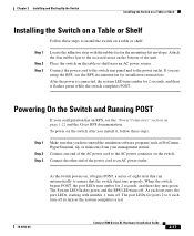
... started the emulation software program (such as the system completes a test. 78-6456-04 Catalyst 3500 Series XL Hardware Installation Guide 2-17 As the switch powers on the switch after you install it flashes green while the switch completes POST. To power on , it begins POST, a series of the power cord.... Connect the other end of eight tests that run automatically to install the switch on page 1-22 and the Cisco RPS documentation. Connect the power cord to the switch rear panel and to the AC power connector on the table or shelf near an AC power source. Connect one end ...
... started the emulation software program (such as the system completes a test. 78-6456-04 Catalyst 3500 Series XL Hardware Installation Guide 2-17 As the switch powers on the switch after you install it flashes green while the switch completes POST. To power on , it begins POST, a series of the power cord.... Connect the other end of eight tests that run automatically to install the switch on page 1-22 and the Cisco RPS documentation. Connect the power cord to the switch rear panel and to the AC power connector on the table or shelf near an AC power source. Connect one end ...
Installation Guide
Page 77
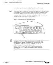
...10 Connecting to a 10/100 Switch Port MODE SYSTEM RPS STATUS UTIL DUPLX SPEED 12 1X 2X 34 56 78 9 10 11 12 11X 12X 22001 Note The Catalyst 3524-PWR XL switch can connect to a Cisco IP Phone through a straight-through Category 5 cable to an RJ-45 connector on page B-4. Refer to the ...documentation that came with your Cisco IP Phone for the cables are described in the "Crossover and ...
...10 Connecting to a 10/100 Switch Port MODE SYSTEM RPS STATUS UTIL DUPLX SPEED 12 1X 2X 34 56 78 9 10 11 12 11X 12X 22001 Note The Catalyst 3524-PWR XL switch can connect to a Cisco IP Phone through a straight-through Category 5 cable to an RJ-45 connector on page B-4. Refer to the ...documentation that came with your Cisco IP Phone for the cables are described in the "Crossover and ...
Installation Guide
Page 78
...on, the device at the other end might be turned on installing and cabling the GigaStack GBICs, see the Catalyst GigaStack Gigabit Interface Converter Hardware Installation Guide. 2-20 Catalyst 3500 Series XL Hardware Installation Guide 78-6456-04 The port LED is amber while Spanning Tree Protocol (STP)...installed in the "GBIC Module Slots" section on page 1-9, and then connect to an RJ-45 connector of the other device. Connecting to the GBIC Module Ports Chapter 2 Installing and Starting Up the Switch Step 2 Step 3 Step 4 Connect the other end of the cable to the 1000BaseX ports....
...on, the device at the other end might be turned on installing and cabling the GigaStack GBICs, see the Catalyst GigaStack Gigabit Interface Converter Hardware Installation Guide. 2-20 Catalyst 3500 Series XL Hardware Installation Guide 78-6456-04 The port LED is amber while Spanning Tree Protocol (STP)...installed in the "GBIC Module Slots" section on page 1-9, and then connect to an RJ-45 connector of the other device. Connecting to the GBIC Module Ports Chapter 2 Installing and Starting Up the Switch Step 2 Step 3 Step 4 Connect the other end of the cable to the 1000BaseX ports....

Installation Guide
Page 79
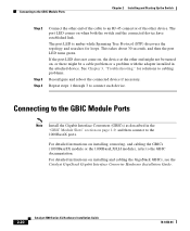
Follow these steps to connect to connect the cable. Insert the SC connector in the fiber-optic receptacle, as shown in Figure 2-11. Chapter 2 Installing and Starting Up the Switch Connecting to the GBIC Module Ports Connecting to a 1000BaseX GBIC Module Port Caution Do not remove the rubber ...contamination and ambient light. Figure 2-11 Connecting to a 1000BaseX Port 1 SYSTEM 2 RPS MODE STATUS UTIL DUPLX SPEED 22005 78-6456-04 Catalyst 3500 Series XL Hardware Installation Guide 2-21 The plugs and caps protect the fiber-optic port and cable from the fiber-optic port on ...
Follow these steps to connect to connect the cable. Insert the SC connector in the fiber-optic receptacle, as shown in Figure 2-11. Chapter 2 Installing and Starting Up the Switch Connecting to the GBIC Module Ports Connecting to a 1000BaseX GBIC Module Port Caution Do not remove the rubber ...contamination and ambient light. Figure 2-11 Connecting to a 1000BaseX Port 1 SYSTEM 2 RPS MODE STATUS UTIL DUPLX SPEED 22005 78-6456-04 Catalyst 3500 Series XL Hardware Installation Guide 2-21 The plugs and caps protect the fiber-optic port and cable from the fiber-optic port on ...
Installation Guide
Page 80
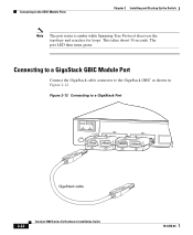
Connecting to a GigaStack Port 32708 MODE 1394 SYSTEM RPS STATUS UTIL DUPLX SPEED 1 1 2 1 2 2 GigaStack cable 1394 2-22 Catalyst 3500 Series XL Hardware Installation Guide 78-6456-04 Figure 2-12 Connecting to the GBIC Module Ports Chapter 2 Installing and Starting Up the Switch Note The port status is amber while Spanning Tree Protocol discovers the topology and searches for loops. Connecting to a GigaStack GBIC Module Port Connect the GigaStack cable connector to the GigaStack GBIC as shown in Figure 2-12. The port LED then turns green. This takes about 30 seconds.
Connecting to a GigaStack Port 32708 MODE 1394 SYSTEM RPS STATUS UTIL DUPLX SPEED 1 1 2 1 2 2 GigaStack cable 1394 2-22 Catalyst 3500 Series XL Hardware Installation Guide 78-6456-04 Figure 2-12 Connecting to the GBIC Module Ports Chapter 2 Installing and Starting Up the Switch Note The port status is amber while Spanning Tree Protocol discovers the topology and searches for loops. Connecting to a GigaStack GBIC Module Port Connect the GigaStack cable connector to the GigaStack GBIC as shown in Figure 2-12. The port LED then turns green. This takes about 30 seconds.
Installation Guide
Page 82
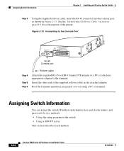
... the supplied RJ-45-to-DB-9 female DTE adapter to a PC or attach an appropriate adapter to the terminal. Assigning Switch Information You can assign the switch IP address information, host and cluster names, and passwords by two methods: • Using the setup program in Figure 2-...of the pinout. Assigning Switch Information Chapter 2 Installing and Starting Up the Switch Step 3 Using the supplied rollover cable, insert the RJ-45 connector into the console port, as shown in the switch • Using a BOOTP server This section describes each method. 2-24 Catalyst 3500 Series XL Hardware ...
... the supplied RJ-45-to-DB-9 female DTE adapter to a PC or attach an appropriate adapter to the terminal. Assigning Switch Information You can assign the switch IP address information, host and cluster names, and passwords by two methods: • Using the setup program in Figure 2-...of the pinout. Assigning Switch Information Chapter 2 Installing and Starting Up the Switch Step 3 Using the supplied rollover cable, insert the RJ-45 connector into the console port, as shown in the switch • Using a BOOTP server This section describes each method. 2-24 Catalyst 3500 Series XL Hardware ...

Installation Guide
Page 101
... straight-through cable schematics). APPENDIX B Connector and Cable Specifications This appendix describes the Catalyst 3500 XL switch ports and the cables and adapters that you use to connect the switch to other switches or repeaters, ensure that a straight-through... cable and adapter can be attached to the port. When connecting to compatible workstations, servers, routers, and Cisco IP Phones, you must use standard RJ-45 connectors...
... straight-through cable schematics). APPENDIX B Connector and Cable Specifications This appendix describes the Catalyst 3500 XL switch ports and the cables and adapters that you use to connect the switch to other switches or repeaters, ensure that a straight-through... cable and adapter can be attached to the port. When connecting to compatible workstations, servers, routers, and Cisco IP Phones, you must use standard RJ-45 connectors...

Installation Guide
Page 102
Connector Specifications Appendix B Connector and Cable Specifications Figure B-1 10/100 Port Pinouts Pin Label 1 RD+ 2 RD- 3 TD+ 4 NC 5 NC 6 TD- 7 NC 8 NC 12345678 H5318 1000BaseX Ports 1000BaseX ports use duplex SC connectors, as shown in Figure B-2. Figure B-2 1000BaseX SC Connector H8707 Tx Rx Catalyst 3500 Series XL Hardware Installation Guide B-2 78-6456-04
Connector Specifications Appendix B Connector and Cable Specifications Figure B-1 10/100 Port Pinouts Pin Label 1 RD+ 2 RD- 3 TD+ 4 NC 5 NC 6 TD- 7 NC 8 NC 12345678 H5318 1000BaseX Ports 1000BaseX ports use duplex SC connectors, as shown in Figure B-2. Figure B-2 1000BaseX SC Connector H8707 Tx Rx Catalyst 3500 Series XL Hardware Installation Guide B-2 78-6456-04