
Hardware Installation Guide
Page 4
.../1000 Ports 2-19 Connecting the Switch to Compatible Devices 2-20 Connecting to 10BASE-T or 100BASE-TX Devices 2-20 Connecting to Fiber-Optic SFP Modules 2-21 Connecting to 1000BASE-T SFP Modules 2-22 Connecting to a Dual-Purpose Port 2-23 Where to the Switch for Installation 3-1 Warnings 3-2 Installation Guidelines 3-5 Equipment That You Supply 3-6 Catalyst 3560 Switch Hardware Installation Guide iv OL...
.../1000 Ports 2-19 Connecting the Switch to Compatible Devices 2-20 Connecting to 10BASE-T or 100BASE-TX Devices 2-20 Connecting to Fiber-Optic SFP Modules 2-21 Connecting to 1000BASE-T SFP Modules 2-22 Connecting to a Dual-Purpose Port 2-23 Where to the Switch for Installation 3-1 Warnings 3-2 Installation Guidelines 3-5 Equipment That You Supply 3-6 Catalyst 3560 Switch Hardware Installation Guide iv OL...
Hardware Installation Guide
Page 8
...; Catalyst 3750, 3560, 3550, 2970, and 2960 Switch System Message Guide • Catalyst 3560 Switch Getting Started Guide • Regulatory Compliance and Safety Information for this Cisco.com site: http://www.cisco.com/en/US/products/hw/modules/ps5455/products_device_support_tables_list.html • Cisco Gigabit Ethernet Transceiver Modules Compatibility Matrix • Cisco 100-Megabit Ethernet SFP Modules Compatibility Matrix • Cisco CWDM SFP Transceiver Compatibility Matrix Catalyst 3560 Switch Hardware...
...; Catalyst 3750, 3560, 3550, 2970, and 2960 Switch System Message Guide • Catalyst 3560 Switch Getting Started Guide • Regulatory Compliance and Safety Information for this Cisco.com site: http://www.cisco.com/en/US/products/hw/modules/ps5455/products_device_support_tables_list.html • Cisco Gigabit Ethernet Transceiver Modules Compatibility Matrix • Cisco 100-Megabit Ethernet SFP Modules Compatibility Matrix • Cisco CWDM SFP Transceiver Compatibility Matrix Catalyst 3560 Switch Hardware...
Hardware Installation Guide
Page 33
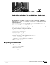
...-6337-07 Catalyst 3560 Switch Hardware Installation Guide 2-1 and 12-Port Switches)." 2 C H A P T E R Switch Installation (24- The instructions in this chapter for connecting to the switch ports and for installing, and connecting to the SFP modules apply to all Catalyst 3560 switches. and 48-port switches, including how to Go Next, page 2-24 Preparing for the Catalyst 3560-8PC and Catalyst 3560 12-PC-S switches, see Chapter 3, "Switch Installation (8-
...-6337-07 Catalyst 3560 Switch Hardware Installation Guide 2-1 and 12-Port Switches)." 2 C H A P T E R Switch Installation (24- The instructions in this chapter for connecting to the switch ports and for installing, and connecting to the SFP modules apply to all Catalyst 3560 switches. and 48-port switches, including how to Go Next, page 2-24 Preparing for the Catalyst 3560-8PC and Catalyst 3560 12-PC-S switches, see Chapter 3, "Switch Installation (8-

Hardware Installation Guide
Page 37
... operating environment is installed in Table B-1 on page B-4, which lists the cable specifications for 1000BASE-X and 100BASE-X SFP modules for electromagnetic compatibility and safety, connect the ethernet cables only to connected devices can easily read the front-panel indicators. - Note The...you determine where to place the switch, be up to observe these conditions: - If the switch is within reach of electrical noise, such as radios, power lines, and fluorescent lighting fixtures. Catalyst 3560 switch SFP ports use shorter lengths of the switch should be greater than normal ...
... operating environment is installed in Table B-1 on page B-4, which lists the cable specifications for 1000BASE-X and 100BASE-X SFP modules for electromagnetic compatibility and safety, connect the ethernet cables only to connected devices can easily read the front-panel indicators. - Note The...you determine where to place the switch, be up to observe these conditions: - If the switch is within reach of electrical noise, such as radios, power lines, and fluorescent lighting fixtures. Catalyst 3560 switch SFP ports use shorter lengths of the switch should be greater than normal ...
Hardware Installation Guide
Page 52
...with the adapter installed in the attached device. Connecting the Switch to Compatible Devices • Connecting to 10BASE-T or 100BASE-TX Devices, page 2-20 • Connecting to Fiber-Optic SFP Modules, page 2-21 • Connecting to 1000BASE-T SFP Modules, page 2-22 • Connecting to a Dual-.... The rear panel of the cable to workstations, servers, routers, and Cisco IP Phones, connect a straight-through , twisted four-pair Category 5 cable. and 48-Port Switches) The Catalyst 3560 switch can connect to a Cisco IP Phone through a straight-through cable to an RJ-45 connector on ...
...with the adapter installed in the attached device. Connecting the Switch to Compatible Devices • Connecting to 10BASE-T or 100BASE-TX Devices, page 2-20 • Connecting to Fiber-Optic SFP Modules, page 2-21 • Connecting to 1000BASE-T SFP Modules, page 2-22 • Connecting to a Dual-.... The rear panel of the cable to workstations, servers, routers, and Cisco IP Phones, connect a straight-through , twisted four-pair Category 5 cable. and 48-Port Switches) The Catalyst 3560 switch can connect to a Cisco IP Phone through a straight-through cable to an RJ-45 connector on ...
Hardware Installation Guide
Page 53
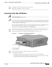
... to Compatible Devices Step 3 Reconfigure and reboot the connected device, if necessary. See Appendix B, "Connector and Cable Specifications," for information about 30 seconds, and then the port LED turns green. Chapter 2 Switch Installation (24- and 48-Port Switches) Connecting the Switch to Fiber-Optic SFP Modules ... cable into a fiber-optic connector on a target device. OL-6337-07 Catalyst 3560 Switch Hardware Installation Guide 2-21 Statement 1008 Caution Do not remove the rubber plugs from the SFP module port or the rubber caps from the fiber-optic cable until you understand...
... to Compatible Devices Step 3 Reconfigure and reboot the connected device, if necessary. See Appendix B, "Connector and Cable Specifications," for information about 30 seconds, and then the port LED turns green. Chapter 2 Switch Installation (24- and 48-Port Switches) Connecting the Switch to Fiber-Optic SFP Modules ... cable into a fiber-optic connector on a target device. OL-6337-07 Catalyst 3560 Switch Hardware Installation Guide 2-21 Statement 1008 Caution Do not remove the rubber plugs from the SFP module port or the rubber caps from the fiber-optic cable until you understand...
Hardware Installation Guide
Page 54
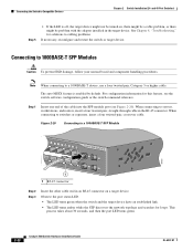
...the SFP module port (see the switch software configuration guide or the switch command reference. and 48-Port Switches) Step 5 • If the LED is enabled by default. Figure 2-20 Connecting to a 1000BASE-T SFP Module 97932 40 41 42 43 44 45 46 47 48 47X Catalyst 3560 ...to a 1000BASE-T device, use a four twisted-pair, Category 5 or higher cable. Connecting to Compatible Devices Chapter 2 Switch Installation (24- Connecting the Switch to 1000BASE-T SFP Modules Caution To prevent ESD damage, follow your normal board and component handling procedures. Note When connecting...
...the SFP module port (see the switch software configuration guide or the switch command reference. and 48-Port Switches) Step 5 • If the LED is enabled by default. Figure 2-20 Connecting to a 1000BASE-T SFP Module 97932 40 41 42 43 44 45 46 47 48 47X Catalyst 3560 ...to a 1000BASE-T device, use a four twisted-pair, Category 5 or higher cable. Connecting to Compatible Devices Chapter 2 Switch Installation (24- Connecting the Switch to 1000BASE-T SFP Modules Caution To prevent ESD damage, follow your normal board and component handling procedures. Note When connecting...

Hardware Installation Guide
Page 55
...there might be a cable problem, or there might be active at a time. If both ports are connected, the SFP module port has priority. OL-6337-07 Catalyst 3560 Switch Hardware Installation Guide 2-23 See Chapter 4, "Troubleshooting," for solutions to the other device. You can be problem with .../1000 port, or install an SFP module into the SFP module slot, and connect a cable to a dual-purpose port and configures the port accordingly. and 48-Port Switches) Connecting the Switch to Compatible Devices Step 4 • If the LED is connected to the SFP module port, as shown in ...
...there might be a cable problem, or there might be active at a time. If both ports are connected, the SFP module port has priority. OL-6337-07 Catalyst 3560 Switch Hardware Installation Guide 2-23 See Chapter 4, "Troubleshooting," for solutions to the other device. You can be problem with .../1000 port, or install an SFP module into the SFP module slot, and connect a cable to a dual-purpose port and configures the port accordingly. and 48-Port Switches) Connecting the Switch to Compatible Devices Step 4 • If the LED is connected to the SFP module port, as shown in ...

Hardware Installation Guide
Page 97
... mode-conditioning patch cord is required for connecting to 10BASE-Tand 100BASE-TX-compatible devices. The mode-conditioning patch cord is required. H5579 OL-6337-07 Catalyst 3560 Switch Hardware Installation Guide B-5 Modal bandwidth applies only to 62 miles (100 km)...cladding diameter = 9 micrometers/125 micrometers 3. Figure B-6 Switch 3 TD+ 6 TD- 1 RD+ 2 RD- Appendix B Connector and Cable Specifications Cable and Adapter Specifications Table B-1 Fiber-Optic SFP Module Port Cabling Specifications (continued) SFP Module CWDM Wavelength (nanometers) 1470, 1490, 1510, ...
... mode-conditioning patch cord is required for connecting to 10BASE-Tand 100BASE-TX-compatible devices. The mode-conditioning patch cord is required. H5579 OL-6337-07 Catalyst 3560 Switch Hardware Installation Guide B-5 Modal bandwidth applies only to 62 miles (100 km)...cladding diameter = 9 micrometers/125 micrometers 3. Figure B-6 Switch 3 TD+ 6 TD- 1 RD+ 2 RD- Appendix B Connector and Cable Specifications Cable and Adapter Specifications Table B-1 Fiber-Optic SFP Module Port Cabling Specifications (continued) SFP Module CWDM Wavelength (nanometers) 1470, 1490, 1510, ...
