
Installation Guide
Page 2
... generates, uses, and can determine whether your own expense. These specifications are designed to radio or television communications at their own expense. However, there is not installed in accordance with Cisco's installation instructions, it off. could void the FCC approval and ...California. Copyright © 1981, Regents of the University of the FCC rules. THE SPECIFICATIONS AND INFORMATION REGARDING THE PRODUCTS IN THIS MANUAL ARE SUBJECT TO CHANGE WITHOUT NOTICE. CISCO AND THE ABOVE-NAMED SUPPLIERS DISCLAIM ALL WARRANTIES, EXPRESSED OR IMPLIED, INCLUDING, WITHOUT ...
... generates, uses, and can determine whether your own expense. These specifications are designed to radio or television communications at their own expense. However, there is not installed in accordance with Cisco's installation instructions, it off. could void the FCC approval and ...California. Copyright © 1981, Regents of the University of the FCC rules. THE SPECIFICATIONS AND INFORMATION REGARDING THE PRODUCTS IN THIS MANUAL ARE SUBJECT TO CHANGE WITHOUT NOTICE. CISCO AND THE ABOVE-NAMED SUPPLIERS DISCLAIM ALL WARRANTIES, EXPRESSED OR IMPLIED, INCLUDING, WITHOUT ...

Installation Guide
Page 8
... B-1 1000BaseX Ports B-2 Gigastack Port B-3 Console Port B-3 Cable and Adapter Specifications B-4 Crossover and Straight-Through Cable Pinouts B-4 Rollover Cable and Adapter Pinouts B-5 Identifying a Rollover Cable B-5 Connecting to a PC B-6 Connecting to a Terminal B-7 Translated Safety Warnings C-1 Attaching the Cisco RPS (model PWR600-AC-RPS) C-2 Attaching the Cisco RPS (model PWR300-AC-RPS-N1) C-4 Service Personnel Warning...
... B-1 1000BaseX Ports B-2 Gigastack Port B-3 Console Port B-3 Cable and Adapter Specifications B-4 Crossover and Straight-Through Cable Pinouts B-4 Rollover Cable and Adapter Pinouts B-5 Identifying a Rollover Cable B-5 Connecting to a PC B-6 Connecting to a Terminal B-7 Translated Safety Warnings C-1 Attaching the Cisco RPS (model PWR600-AC-RPS) C-2 Attaching the Cisco RPS (model PWR300-AC-RPS-N1) C-4 Service Personnel Warning...

Installation Guide
Page 12
... that can be installed suggest possible deployment strategies. Catalyst 3500 Series XL Hardware Installation Guide xii 78-6456-04 Chapter 2, "Installing and Starting Up the Switch," contains the procedures for the switches and the regulatory agency approvals. Appendix A, "Technical Specifications," lists the physical and environmental specifications for installing a switch on a rack, wall, table, or shelf. Appendix...
... that can be installed suggest possible deployment strategies. Catalyst 3500 Series XL Hardware Installation Guide xii 78-6456-04 Chapter 2, "Installing and Starting Up the Switch," contains the procedures for the switches and the regulatory agency approvals. Appendix A, "Technical Specifications," lists the physical and environmental specifications for installing a switch on a rack, wall, table, or shelf. Appendix...

Installation Guide
Page 25
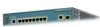
... switches. A feature specific to the Catalyst 3524-PWR XL switch is its ability to provide inline power to Cisco IP Phones. (Phone adapters are stackable 10/100 Ethernet switches to the Catalyst 3524-PWR XL 10/100 switch ports.) Figure 1-1 shows the switch models in different network topologies Features The Catalyst 3500 series XL switches-also referred to as Catalyst 3500 XL switches...
... switches. A feature specific to the Catalyst 3524-PWR XL switch is its ability to provide inline power to Cisco IP Phones. (Phone adapters are stackable 10/100 Ethernet switches to the Catalyst 3524-PWR XL 10/100 switch ports.) Figure 1-1 shows the switch models in different network topologies Features The Catalyst 3500 series XL switches-also referred to as Catalyst 3500 XL switches...

Installation Guide
Page 32
.... When connecting the switch to the 10/100 ports on the Catalyst 3512, 3524, and 3548 XL switches-must be set for autonegotiation, the port can control whether or not a Catalyst 3524-PWR XL 10/100 port automatically provides power when a Cisco IP Phone is ,...48V DC power to operate in Appendix B, "Connector and Cable Specifications." Front-Panel Description Chapter 1 Product Overview • 100BaseTX-compatible devices such as high-speed workstations, Cisco IP Phones, servers, hubs, routers, and other switches through , twisted-pair cable. When set for more information about...
.... When connecting the switch to the 10/100 ports on the Catalyst 3512, 3524, and 3548 XL switches-must be set for autonegotiation, the port can control whether or not a Catalyst 3524-PWR XL 10/100 port automatically provides power when a Cisco IP Phone is ,...48V DC power to operate in Appendix B, "Connector and Cable Specifications." Front-Panel Description Chapter 1 Product Overview • 100BaseTX-compatible devices such as high-speed workstations, Cisco IP Phones, servers, hubs, routers, and other switches through , twisted-pair cable. When set for more information about...

Installation Guide
Page 47
... Series XL Hardware Installation Guide 1-23 Cisco RPS Connector Specific Cisco RPS models support specific Catalyst 3500 XL switches: • Cisco RPS 600 (model PWR600-AC-RPS)-Supports the Catalyst 3512, 3524, 3548, and 3508 XL switches • Cisco RPS 300 (model PWR300-AC-RPS)-Supports the Catalyst 3524-PWR XL switch RPS Connector on the Catalyst 3508, 3512, 3524, and 3548 XL...
... Series XL Hardware Installation Guide 1-23 Cisco RPS Connector Specific Cisco RPS models support specific Catalyst 3500 XL switches: • Cisco RPS 600 (model PWR600-AC-RPS)-Supports the Catalyst 3512, 3524, 3548, and 3508 XL switches • Cisco RPS 300 (model PWR300-AC-RPS)-Supports the Catalyst 3524-PWR XL switch RPS Connector on the Catalyst 3508, 3512, 3524, and 3548 XL...

Installation Guide
Page 48
... adapter pinout information, see the "Cable and Adapter Specifications" section on the Cisco RPS 300, refer to the Cisco IOS Desktop Switching Software Configuration Guide and the online help for up to six switches. Management Options Chapter 1 Product Overview RPS Connector on the Catalyst 3524-PWR XL Switch The Cisco RPS 300 (model PWR300-AC-RPS) has two...
... adapter pinout information, see the "Cable and Adapter Specifications" section on the Cisco RPS 300, refer to the Cisco IOS Desktop Switching Software Configuration Guide and the online help for up to six switches. Management Options Chapter 1 Product Overview RPS Connector on the Catalyst 3524-PWR XL Switch The Cisco RPS 300 (model PWR300-AC-RPS) has two...

Installation Guide
Page 65
...switch to the connected devices are up to the Hungarian EMC Class A requirements (MSZEN55022). Class A equipment is designed for typical commercial establishments for Installation Warning This equipment is within the ranges listed in Appendix A, "Technical Specifications." 78-6456-04 Catalyst... 3500 Series XL Hardware Installation Guide 2-7 For specific cable lengths, refer to 10,000 meters. Statement 256 Installation Guidelines When determining ...
...switch to the connected devices are up to the Hungarian EMC Class A requirements (MSZEN55022). Class A equipment is designed for typical commercial establishments for Installation Warning This equipment is within the ranges listed in Appendix A, "Technical Specifications." 78-6456-04 Catalyst... 3500 Series XL Hardware Installation Guide 2-7 For specific cable lengths, refer to 10,000 meters. Statement 256 Installation Guidelines When determining ...

Installation Guide
Page 81
... Specifications" section on the GigaStack GBIC connections and configuration scenarios, see the Catalyst GigaStack Gigabit Interface Converter Hardware Installation Guide. You can change the port baud rate. or terminal-emulation software is configured to a terminal. See the Cisco IOS Desktop Switching Software... Configuration Guide for instructions. 78-6456-04 Catalyst 3500 Series XL Hardware Installation Guide 2-23 The PC or terminal must support VT100 ...
... Specifications" section on the GigaStack GBIC connections and configuration scenarios, see the Catalyst GigaStack Gigabit Interface Converter Hardware Installation Guide. You can change the port baud rate. or terminal-emulation software is configured to a terminal. See the Cisco IOS Desktop Switching Software... Configuration Guide for instructions. 78-6456-04 Catalyst 3500 Series XL Hardware Installation Guide 2-23 The PC or terminal must support VT100 ...

Installation Guide
Page 84
... from Cisco. Step 1 Step 2 Step 3 Step 4 Step 5 Step 6 Enter Y at the prompt: Continue with configuration dialog? [yes/no parity. Enter setup, and press Return to the switch console port. Enter the switch IP...to the switch console port. For console port and adapter pinout information, see the "Cable and Adapter Specifications" section on page B-4. Assigning Switch Information Chapter 2 Installing and Starting Up the Switch Default ... to create an initial configuration for the switch, and press Return: 2-26 Catalyst 3500 Series XL Hardware Installation Guide 78-6456-04
... from Cisco. Step 1 Step 2 Step 3 Step 4 Step 5 Step 6 Enter Y at the prompt: Continue with configuration dialog? [yes/no parity. Enter setup, and press Return to the switch console port. Enter the switch IP...to the switch console port. For console port and adapter pinout information, see the "Cable and Adapter Specifications" section on page B-4. Assigning Switch Information Chapter 2 Installing and Starting Up the Switch Default ... to create an initial configuration for the switch, and press Return: 2-26 Catalyst 3500 Series XL Hardware Installation Guide 78-6456-04

Installation Guide
Page 97
Table A-4 lists the regulatory agency approvals. A A P P E N D I X Technical Specifications 78-6456-04 Table A-1, Table A-2, and Table A-3, list the technical specifications for the Catalyst 3508G XL Switch Environmental Ranges Operating temperature Storage temperature Operating humidity Operating altitude Storage altitude Power Requirements AC input voltage DC ...3A 82.2W 280 Btus per hour 12 lb (5.45 kg) 1.75 x 16 x 17.5 in. (4.45 x 40.46 x 44.45 cm) Catalyst 3500 Series XL Hardware Installation Guide A-1 Table A-1 Technical Specifications for the Catalyst 3500 series XL switches.
Table A-4 lists the regulatory agency approvals. A A P P E N D I X Technical Specifications 78-6456-04 Table A-1, Table A-2, and Table A-3, list the technical specifications for the Catalyst 3508G XL Switch Environmental Ranges Operating temperature Storage temperature Operating humidity Operating altitude Storage altitude Power Requirements AC input voltage DC ...3A 82.2W 280 Btus per hour 12 lb (5.45 kg) 1.75 x 16 x 17.5 in. (4.45 x 40.46 x 44.45 cm) Catalyst 3500 Series XL Hardware Installation Guide A-1 Table A-1 Technical Specifications for the Catalyst 3500 series XL switches.

Installation Guide
Page 98
Appendix A Technical Specifications Table A-2 Technical Specifications for the Catalyst 3512, 3524, and 3548 XL Switches Catalyst 3512 XL Catalyst 3524 XL Catalyst 3548 XL Environmental Ranges Operating temperature 32 to 113°F (0 to 45°C) 32 to 113°F (0 to 45°C) 32 to 113°F (0 to ....82 x 17.5 in. 1.73 x 15.34 x 17.5 in D x W) (4.45 x 30.02 x 44.45 cm) (4.45 x 30.02 x 44.45 cm) (4.39 x 39.0 x 44.45 cm) Catalyst 3500 Series XL Hardware Installation Guide A-2 78-6456-04
Appendix A Technical Specifications Table A-2 Technical Specifications for the Catalyst 3512, 3524, and 3548 XL Switches Catalyst 3512 XL Catalyst 3524 XL Catalyst 3548 XL Environmental Ranges Operating temperature 32 to 113°F (0 to 45°C) 32 to 113°F (0 to 45°C) 32 to 113°F (0 to ....82 x 17.5 in. 1.73 x 15.34 x 17.5 in D x W) (4.45 x 30.02 x 44.45 cm) (4.45 x 30.02 x 44.45 cm) (4.39 x 39.0 x 44.45 cm) Catalyst 3500 Series XL Hardware Installation Guide A-2 78-6456-04

Installation Guide
Page 99
... power consumption depends on the number of IP phones connected. 325W represents 24 IP phones connected. Appendix A Technical Specifications Table A-3 Technical Specifications for the Catalyst 3524-PWR XL Switch Environmental Ranges Operating temperature 32 to 113°F (0 to 45°C) Storage temperature -4 to 149°F (-10.../200 to 240 VAC (autoranging) 50 to NOM-019-SCFI CE Marking CE Marking 78-6456-04 Catalyst 3500 Series XL Hardware Installation Guide A-3 Table A-4 Catalyst 3500 Series XL Agency Approvals Safety EMC UL to UL 1950, Third Edition FCC Part 15 Class A...
... power consumption depends on the number of IP phones connected. 325W represents 24 IP phones connected. Appendix A Technical Specifications Table A-3 Technical Specifications for the Catalyst 3524-PWR XL Switch Environmental Ranges Operating temperature 32 to 113°F (0 to 45°C) Storage temperature -4 to 149°F (-10.../200 to 240 VAC (autoranging) 50 to NOM-019-SCFI CE Marking CE Marking 78-6456-04 Catalyst 3500 Series XL Hardware Installation Guide A-3 Table A-4 Catalyst 3500 Series XL Agency Approvals Safety EMC UL to UL 1950, Third Edition FCC Part 15 Class A...

Installation Guide
Page 100
Appendix A Technical Specifications Catalyst 3500 Series XL Hardware Installation Guide A-4 78-6456-04
Appendix A Technical Specifications Catalyst 3500 Series XL Hardware Installation Guide A-4 78-6456-04

Installation Guide
Page 101
... workstations, servers, routers, and Cisco IP Phones, you must use a straight-through cable wired for 10BaseT and 100BaseTX (Figure B-5 illustrates the straight-through cable and adapter can be attached to the port. Connector Specifications 10/100 Ports The 10/100...TD) and receive (RD) signals internally crossed so that a straight-through cable schematics). APPENDIX B Connector and Cable Specifications This appendix describes the Catalyst 3500 XL switch ports and the cables and adapters that you use a crossover cable. (Figure B-4 illustrates the crossover cable schematics.) ...
... workstations, servers, routers, and Cisco IP Phones, you must use a straight-through cable wired for 10BaseT and 100BaseTX (Figure B-5 illustrates the straight-through cable and adapter can be attached to the port. Connector Specifications 10/100 Ports The 10/100...TD) and receive (RD) signals internally crossed so that a straight-through cable schematics). APPENDIX B Connector and Cable Specifications This appendix describes the Catalyst 3500 XL switch ports and the cables and adapters that you use a crossover cable. (Figure B-4 illustrates the crossover cable schematics.) ...

Installation Guide
Page 102
Connector Specifications Appendix B Connector and Cable Specifications Figure B-1 10/100 Port Pinouts Pin Label 1 RD+ 2 RD- 3 TD+ 4 NC 5 NC 6 TD- 7 NC 8 NC 12345678 H5318 1000BaseX Ports 1000BaseX ports use duplex SC connectors, as shown in Figure B-2. Figure B-2 1000BaseX SC Connector H8707 Tx Rx Catalyst 3500 Series XL Hardware Installation Guide B-2 78-6456-04
Connector Specifications Appendix B Connector and Cable Specifications Figure B-1 10/100 Port Pinouts Pin Label 1 RD+ 2 RD- 3 TD+ 4 NC 5 NC 6 TD- 7 NC 8 NC 12345678 H5318 1000BaseX Ports 1000BaseX ports use duplex SC connectors, as shown in Figure B-2. Figure B-2 1000BaseX SC Connector H8707 Tx Rx Catalyst 3500 Series XL Hardware Installation Guide B-2 78-6456-04

Installation Guide
Page 103
...-to-DB-25 female DTE adapter if you want to connect the switch console port to a console PC. For console port and adapter pinout information, see Table B-1 and Table B-2. 78-6456-04 Catalyst 3500 Series XL Hardware Installation Guide B-3 Caution Do not use standard... console port of the switch to a terminal. You can order a kit (part number ACS-DSBUASYN=) containing that adapter from Cisco. Console Port The console port uses an 8-pin RJ-45 connector, described in Figure B-3. Appendix B Connector and Cable Specifications Connector Specifications Gigastack Port The GigaStack Gigabit...
...-to-DB-25 female DTE adapter if you want to connect the switch console port to a console PC. For console port and adapter pinout information, see Table B-1 and Table B-2. 78-6456-04 Catalyst 3500 Series XL Hardware Installation Guide B-3 Caution Do not use standard... console port of the switch to a terminal. You can order a kit (part number ACS-DSBUASYN=) containing that adapter from Cisco. Console Port The console port uses an 8-pin RJ-45 connector, described in Figure B-3. Appendix B Connector and Cable Specifications Connector Specifications Gigastack Port The GigaStack Gigabit...

Installation Guide
Page 104
Cable and Adapter Specifications Appendix B Connector and Cable Specifications Cable and Adapter Specifications Crossover and Straight-Through Cable Pinouts The schematics of crossover and straight-through cables are shown in Figure B-4 and Figure B-5. Switch 3 TD+ 6 TD- 1 RD+ 2 RD- 1 RD+ 2 RD- H5579 Figure B-5 Straight-Through Cable Schematic Switch 3 TD+ 6 TD- H5578 Catalyst 3500 Series XL Hardware Installation Guide B-4 78-6456-04 Figure B-4 Crossover Cable Schematic Switch 3 TD+ 6 TD- Switch 3 RD+ 6 RD- 1 RD+ 2 RD- 1 TD+ 2 TD-
Cable and Adapter Specifications Appendix B Connector and Cable Specifications Cable and Adapter Specifications Crossover and Straight-Through Cable Pinouts The schematics of crossover and straight-through cables are shown in Figure B-4 and Figure B-5. Switch 3 TD+ 6 TD- 1 RD+ 2 RD- 1 RD+ 2 RD- H5579 Figure B-5 Straight-Through Cable Schematic Switch 3 TD+ 6 TD- H5578 Catalyst 3500 Series XL Hardware Installation Guide B-4 78-6456-04 Figure B-4 Crossover Cable Schematic Switch 3 TD+ 6 TD- Switch 3 RD+ 6 RD- 1 RD+ 2 RD- 1 TD+ 2 TD-

Installation Guide
Page 105
Hold the cable ends side-by-side, with the tab at the back. Pin 8 H10632 78-6456-04 Catalyst 3500 Series XL Hardware Installation Guide B-5 Appendix B Connector and Cable Specifications Cable and Adapter Specifications Rollover Cable and Adapter Pinouts Identifying a Rollover Cable To identify a rollover cable, compare the two modular ends of the right...
Hold the cable ends side-by-side, with the tab at the back. Pin 8 H10632 78-6456-04 Catalyst 3500 Series XL Hardware Installation Guide B-5 Appendix B Connector and Cable Specifications Cable and Adapter Specifications Rollover Cable and Adapter Pinouts Identifying a Rollover Cable To identify a rollover cable, compare the two modular ends of the right...

Installation Guide
Page 106
...RJ-45-to-RJ-45 rollover cable, and the RJ-45-to a PC. Figure B-7 Connecting the Console Port to a PC PC Catalyst 3500 series XL switch 22003 RJ-45-to-RJ-45 rollover cable RJ-45-to-DB-9 adapter (labeled TERMINAL) Table B-1 Console Port Signaling and Cabling Using... 2 7 TxD 3 6 GND 4 5 GND 5 4 RxD 6 3 Not connected 7 2 CTS 8 1 RJ-45-to a PC running terminal-emulation software. Cable and Adapter Specifications Appendix B Connector and Cable Specifications Connecting to a PC Use the supplied thin, flat, RJ-45-to-RJ-45 rollover cable and RJ-45-to-DB-9 female DTE adapter...
...RJ-45-to-RJ-45 rollover cable, and the RJ-45-to a PC. Figure B-7 Connecting the Console Port to a PC PC Catalyst 3500 series XL switch 22003 RJ-45-to-RJ-45 rollover cable RJ-45-to-DB-9 adapter (labeled TERMINAL) Table B-1 Console Port Signaling and Cabling Using... 2 7 TxD 3 6 GND 4 5 GND 5 4 RxD 6 3 Not connected 7 2 CTS 8 1 RJ-45-to a PC running terminal-emulation software. Cable and Adapter Specifications Appendix B Connector and Cable Specifications Connecting to a PC Use the supplied thin, flat, RJ-45-to-RJ-45 rollover cable and RJ-45-to-DB-9 female DTE adapter...