
Installation Guide
Page 60
Statement 1004 Warning Before working on any other equipment. Statement 66 Catalyst 3500 Series XL Hardware Installation Guide 2-2 78-6456-04 Preparing for Installation Chapter 2 Installing and Starting Up the Switch Preparing for Installation Warnings These warnings are translated into several languages in Appendix C, "...is to be accessible at all times because it can cause serious burns or weld the metal object to install or replace this equipment. Statement 48 Warning The plug-socket combination must be installed and maintained by service personnel only as the main...
Statement 1004 Warning Before working on any other equipment. Statement 66 Catalyst 3500 Series XL Hardware Installation Guide 2-2 78-6456-04 Preparing for Installation Chapter 2 Installing and Starting Up the Switch Preparing for Installation Warnings These warnings are translated into several languages in Appendix C, "...is to be accessible at all times because it can cause serious burns or weld the metal object to install or replace this equipment. Statement 48 Warning The plug-socket combination must be installed and maintained by service personnel only as the main...
Installation Guide
Page 64
When such trouble occurs, the user may arise. The seller or buyer should be replaced with a residential-use . Statement 294 Catalyst 3500 Series XL Hardware Installation Guide 2-6 78-6456-04 If this equipment is registered for EMC requirements for Interference by mistake, it should be ... be aware of this type was sold or purchased by Information Technology Equipment (VCCI). Preparing for Installation Japan Chapter 2 Installing and Starting Up the Switch Warning This is a Class A product based on the standard of the Voluntary Control Council for industrial use type.
When such trouble occurs, the user may arise. The seller or buyer should be replaced with a residential-use . Statement 294 Catalyst 3500 Series XL Hardware Installation Guide 2-6 78-6456-04 If this equipment is registered for EMC requirements for Interference by mistake, it should be ... be aware of this type was sold or purchased by Information Technology Equipment (VCCI). Preparing for Installation Japan Chapter 2 Installing and Starting Up the Switch Warning This is a Class A product based on the standard of the Voluntary Control Council for industrial use type.
Installation Guide
Page 95
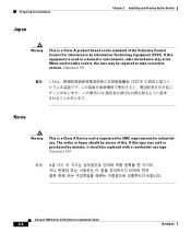
...proper application of crossover vs. straight-through was required, or vice-versa. • The cable is amber on the Catalyst 3508, 3512, or 3524 XL switch. Use the show POST command to see the "Crossover and Straight-Through Cable Pinouts" section on the management console. ...failed. 78-6456-04 Catalyst 3500 Series XL Hardware Installation Guide 3-5 System LED is wired incorrectly. • STP checking for LED to 9600 baud. Nonfatal or fatal POST error detected. Reset the emulation software to turn green. Unreadable characters on page B-4. • Replace with a tested good ...
...proper application of crossover vs. straight-through was required, or vice-versa. • The cable is amber on the Catalyst 3508, 3512, or 3524 XL switch. Use the show POST command to see the "Crossover and Straight-Through Cable Pinouts" section on the management console. ...failed. 78-6456-04 Catalyst 3500 Series XL Hardware Installation Guide 3-5 System LED is wired incorrectly. • STP checking for LED to 9600 baud. Nonfatal or fatal POST error detected. Reset the emulation software to turn green. Unreadable characters on page B-4. • Replace with a tested good ...

Installation Guide
Page 96
...Replace the switch at your convenience. • Use the show env command to -phone jack on Improper cabling. Catalyst 3500 Series XL Hardware Installation Guide 3-6 78-6456-04 Make sure the switch is connected to the LAN-to check if an overtemperature condition exists. Cisco IP Phone fails to a Catalyst 3524-PWR XL switch. The Catalyst... on the switch has failed. Resolution • Either check the switch itself or use the show POST command to check if a fan on the Catalyst 3524-PWR XL. If a multiple-fan failure is causing the switch to overheat, replace the switch. •...
...Replace the switch at your convenience. • Use the show env command to -phone jack on Improper cabling. Catalyst 3500 Series XL Hardware Installation Guide 3-6 78-6456-04 Make sure the switch is connected to the LAN-to check if an overtemperature condition exists. Cisco IP Phone fails to a Catalyst 3524-PWR XL switch. The Catalyst... on the switch has failed. Resolution • Either check the switch itself or use the show POST command to check if a fan on the Catalyst 3524-PWR XL. If a multiple-fan failure is causing the switch to overheat, replace the switch. •...

Hardware Installation Guide
Page 20
...purpose uplink, see the software configuration guide. For information about configuring speed and duplex settings for the active connector. 1-10 Catalyst 3560 Switch Hardware Installation Guide OL-6337-07 These transceiver modules are not redundant interfaces. Use a Category 5 cable with dual front ...-replaceable, providing uplink interfaces when inserted in the "SFP Module Cable Specifications" section on page 2-18 for more information about using the SFP module patch cable. Front Panel Description Chapter 1 Product Overview Many legacy powered devices, including older Cisco IP...
...purpose uplink, see the software configuration guide. For information about configuring speed and duplex settings for the active connector. 1-10 Catalyst 3560 Switch Hardware Installation Guide OL-6337-07 These transceiver modules are not redundant interfaces. Use a Category 5 cable with dual front ...-replaceable, providing uplink interfaces when inserted in the "SFP Module Cable Specifications" section on page 2-18 for more information about using the SFP module patch cable. Front Panel Description Chapter 1 Product Overview Many legacy powered devices, including older Cisco IP...

Hardware Installation Guide
Page 36
...terminals. Statement 1072 Warning No user-serviceable parts inside. Statement 1046 Warning This warning symbol means danger. Statement 1074 Catalyst 3560 Switch Hardware Installation Guide 2-4 OL-6337-07 Contact the appropriate electrical inspection authority or an electrician if you work on ...conductor. Statement 1030 Warning Ultimate disposal of the equipment must be removed to install, replace, or service this device. Statement 1044 Warning When installing or replacing the unit, the ground connection must be familiar with integral circuit protection: 10/100...
...terminals. Statement 1072 Warning No user-serviceable parts inside. Statement 1046 Warning This warning symbol means danger. Statement 1074 Catalyst 3560 Switch Hardware Installation Guide 2-4 OL-6337-07 Contact the appropriate electrical inspection authority or an electrician if you work on ...conductor. Statement 1030 Warning Ultimate disposal of the equipment must be removed to install, replace, or service this device. Statement 1044 Warning When installing or replacing the unit, the ground connection must be familiar with integral circuit protection: 10/100...
Hardware Installation Guide
Page 47
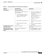
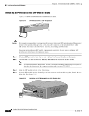
...Catalyst 3560 Switch Getting Started Guide for the list of the switch. Installing and Removing SFP Modules The SFP modules are not being used, replace the dust covers on installing, removing, and cabling the SFP module, see Appendix D, "Configuring the Switch with the rubber feet in the rack: 1. After the switch is encoded with security information, which Cisco...the SFP module documentation. OL-6337-07 Catalyst 3560 Switch Hardware Installation Guide 2-15 and 48-Port Switches) Installing and Removing SFP Modules Table- Use only Cisco SFP modules. Note When the connectors are...
...Catalyst 3560 Switch Getting Started Guide for the list of the switch. Installing and Removing SFP Modules The SFP modules are not being used, replace the dust covers on installing, removing, and cabling the SFP module, see Appendix D, "Configuring the Switch with the rubber feet in the rack: 1. After the switch is encoded with security information, which Cisco...the SFP module documentation. OL-6337-07 Catalyst 3560 Switch Hardware Installation Guide 2-15 and 48-Port Switches) Installing and Removing SFP Modules Table- Use only Cisco SFP modules. Note When the connectors are...
Hardware Installation Guide
Page 48
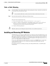
...RX) markings that show the direction of the SFP module. Note On some SFP modules, the send and receive (TX and RX) markings might be replaced by arrows that identify the top side of the connection, either send or receive (TX or RX). Disconnect all cables before removing or installing an... SFP Modules into an SFP Module Slot 40 41 42 43 44 45 46 47 48 47X Catalyst 3560 SERIES PoE-48 1 3 48X 2 4 97928 2-16 Catalyst 3560 Switch Hardware Installation Guide OL-6337-07 Do not remove and insert SFP modules more often than is absolutely necessary. Figure 2-13 SFP Module with a ...
...RX) markings that show the direction of the SFP module. Note On some SFP modules, the send and receive (TX and RX) markings might be replaced by arrows that identify the top side of the connection, either send or receive (TX or RX). Disconnect all cables before removing or installing an... SFP Modules into an SFP Module Slot 40 41 42 43 44 45 46 47 48 47X Catalyst 3560 SERIES PoE-48 1 3 48X 2 4 97928 2-16 Catalyst 3560 Switch Hardware Installation Guide OL-6337-07 Do not remove and insert SFP modules more often than is absolutely necessary. Figure 2-13 SFP Module with a ...
Hardware Installation Guide
Page 60
...may exist on any equipment, be aware of a suitably installed ground conductor. All connections must be removed to install, replace, or service this equipment. Statement 1028 Warning Only trained and qualified personnel should be handled according to locate its translation ... No user-serviceable parts inside. Statement 1074 Catalyst 3560 Switch Hardware Installation Guide 3-4 OL-6337-07 Preparing for preventing accidents. Statement 1030 Warning Ultimate disposal of this device. Statement 1044 Warning When installing or replacing the unit, the ground connection must be ...
...may exist on any equipment, be aware of a suitably installed ground conductor. All connections must be removed to install, replace, or service this equipment. Statement 1028 Warning Only trained and qualified personnel should be handled according to locate its translation ... No user-serviceable parts inside. Statement 1074 Catalyst 3560 Switch Hardware Installation Guide 3-4 OL-6337-07 Preparing for preventing accidents. Statement 1030 Warning Ultimate disposal of this device. Statement 1044 Warning When installing or replacing the unit, the ground connection must be ...
Hardware Installation Guide
Page 79
... port can cause one side to function at a marginal level. Each Cisco module has an internal serial EEPROM that is not. Verify that the cable is fully functional. Enable auto-MDIX on the switch, or replace the cable. A link LED does not guarantee that this module supports ... or the reverse. This encoding provides a way for Cisco to identify and validate that causes it to show interfaces privileged EXEC command to be seated, but the other side does not have link. OL-6337-07 Catalyst 3560 Switch Hardware Installation Guide 4-3 The cable might have encountered physical...
... port can cause one side to function at a marginal level. Each Cisco module has an internal serial EEPROM that is not. Verify that the cable is fully functional. Enable auto-MDIX on the switch, or replace the cable. A link LED does not guarantee that this module supports ... or the reverse. This encoding provides a way for Cisco to identify and validate that causes it to show interfaces privileged EXEC command to be seated, but the other side does not have link. OL-6337-07 Catalyst 3560 Switch Hardware Installation Guide 4-3 The cable might have encountered physical...
Hardware Installation Guide
Page 105
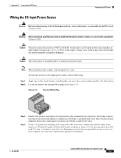
... Only trained and qualified personnel should be installed with all applicable codes. The switch rear panel identifies the positive and negative positions for both the A and B feed wires. OL-6337-07 Catalyst 3560 Switch Hardware Installation Guide C-5 Appendix C Connecting to DC Power Connecting to DC Power...Statement 1030 Caution You must be allowed to -72 VDC. The wiring sequence is removed from -36 to install, replace, or service this range, the switch might not operate properly or might be damaged. Using a 18-gauge wire-stripping tool, strip each of insulation from...
... Only trained and qualified personnel should be installed with all applicable codes. The switch rear panel identifies the positive and negative positions for both the A and B feed wires. OL-6337-07 Catalyst 3560 Switch Hardware Installation Guide C-5 Appendix C Connecting to DC Power Connecting to DC Power...Statement 1030 Caution You must be allowed to -72 VDC. The wiring sequence is removed from -36 to install, replace, or service this range, the switch might not operate properly or might be damaged. Using a 18-gauge wire-stripping tool, strip each of insulation from...