
Installation Guide
Page 7
...Switch in a Rack 2-9 Removing Screws from the Switch 2-10 Attaching the Brackets to the Switch 2-11 Mounting the Switch in a Rack 2-13 Attaching the Optional Cable Guide 2-13 Installing the Switch on a Wall 2-15 Attaching the Brackets to the Switch 2-15 Attaching the Switch to a Wall 2-16 Installing the Switch on a Table or Shelf 2-17 Powering On the Switch...21 Connecting to a GigaStack GBIC Module Port 2-22 Connecting a PC or Terminal to the Console Port 2-23 Assigning Switch Information 2-24 Using the Setup Program 2-25 Using BOOTP 2-29 Default Configuration Settings 2-29 Where to Go Next 2-31...
...Switch in a Rack 2-9 Removing Screws from the Switch 2-10 Attaching the Brackets to the Switch 2-11 Mounting the Switch in a Rack 2-13 Attaching the Optional Cable Guide 2-13 Installing the Switch on a Wall 2-15 Attaching the Brackets to the Switch 2-15 Attaching the Switch to a Wall 2-16 Installing the Switch on a Table or Shelf 2-17 Powering On the Switch...21 Connecting to a GigaStack GBIC Module Port 2-22 Connecting a PC or Terminal to the Console Port 2-23 Assigning Switch Information 2-24 Using the Setup Program 2-25 Using BOOTP 2-29 Default Configuration Settings 2-29 Where to Go Next 2-31...

Installation Guide
Page 9
INDEX Grounded Equipment Warning C-23 Supply Circuit Warning C-24 No On/Off Switch Warning C-25 Power Supply Warning C-27 Work During Lightning Activity Warning C-30 Product Disposal Warning C-31 Chassis Warning-Rack-Mounting and Servicing C-33 Chassis Power Connection Warning C-38 Shock Hazard from Interconnections Warning C-41 Contents 78-6456-03 Catalyst 3500 Series XL Hardware Installation Guide ix
INDEX Grounded Equipment Warning C-23 Supply Circuit Warning C-24 No On/Off Switch Warning C-25 Power Supply Warning C-27 Work During Lightning Activity Warning C-30 Product Disposal Warning C-31 Chassis Warning-Rack-Mounting and Servicing C-33 Chassis Power Connection Warning C-38 Shock Hazard from Interconnections Warning C-41 Contents 78-6456-03 Catalyst 3500 Series XL Hardware Installation Guide ix
Installation Guide
Page 67
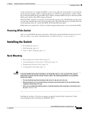
... the switch - The rack-mounting brackets supplied with stabilizing devices, install the stabilizers before mounting or servicing the unit in the rack. Chapter 2 Installing and Starting Up the Switch Installing the Switch in a rack, you must take special precautions to the rack. 78-6456-04 Catalyst 3500 ...to-DB-9 female adapter • Cisco Information Packet, containing warranty, safety, and support information Installing the Switch in a Rack Warning To prevent bodily injury when mounting or servicing this unit in a partially filled rack, load the rack from the bottom to the top with...
... the switch - The rack-mounting brackets supplied with stabilizing devices, install the stabilizers before mounting or servicing the unit in the rack. Chapter 2 Installing and Starting Up the Switch Installing the Switch in a rack, you must take special precautions to the rack. 78-6456-04 Catalyst 3500 ...to-DB-9 female adapter • Cisco Information Packet, containing warranty, safety, and support information Installing the Switch in a Rack Warning To prevent bodily injury when mounting or servicing this unit in a partially filled rack, load the rack from the bottom to the top with...
Installation Guide
Page 68
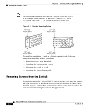
...-04 Figure 2-2 shows how to install the Catalyst 3548 XL switch in a rack, you must first remove the front side screws in the switch chassis so that the mounting brackets can also be attached. Figure 2-1 Bracket Mounting Points 19" rack mount point 24" rack mount point 38398 19" rack mount point 24" rack mount point To install the switch in a 19-inch or a 24-inch...
...-04 Figure 2-2 shows how to install the Catalyst 3548 XL switch in a rack, you must first remove the front side screws in the switch chassis so that the mounting brackets can also be attached. Figure 2-1 Bracket Mounting Points 19" rack mount point 24" rack mount point 38398 19" rack mount point 24" rack mount point To install the switch in a 19-inch or a 24-inch...
Installation Guide
Page 71
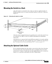
...6456-04 Catalyst 3500 Series XL Hardware Installation Guide 2-13 After the power is mounted in the rack, attach the power cord to the switch. If you are attached to the switch, use the supplied black screw, as shown in Figure 2-5. Figure 2-5 Mounting the Switch in a Rack 26233 ... machine screws After the switch is connected, the System LED turns amber for installation instructions. Chapter 2 Installing and Starting Up the Switch Installing the Switch in a Rack Mounting the Switch in a Rack After the brackets are using the Cisco RPS, see the Cisco RPS documentation for 2 seconds...
...6456-04 Catalyst 3500 Series XL Hardware Installation Guide 2-13 After the power is mounted in the rack, attach the power cord to the switch. If you are attached to the switch, use the supplied black screw, as shown in Figure 2-5. Figure 2-5 Mounting the Switch in a Rack 26233 ... machine screws After the switch is connected, the System LED turns amber for installation instructions. Chapter 2 Installing and Starting Up the Switch Installing the Switch in a Rack Mounting the Switch in a Rack After the brackets are using the Cisco RPS, see the Cisco RPS documentation for 2 seconds...
Installation Guide
Page 72
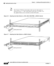
...guide screw 28324 2-14 Catalyst 3500 Series XL Hardware Installation Guide 78-6456-04 22441 Installing the Switch in a Rack Chapter 2 Installing and Starting Up the Switch Note The Catalyst 3548 XL switch ships with a special ...cable guide as shown in Figure 2-7. Figure 2-6 Attaching the Cable Guide to a 3512, 3524, 3524-PWR, or 3508 XL Switch 1 MODE SYSTEM RPS 2 3 4 5 STATUS UTIL DUPLX SPEED 6 7 8 Cable guide screw Figure 2-7 Attaching the Cable Guide to mount...
...guide screw 28324 2-14 Catalyst 3500 Series XL Hardware Installation Guide 78-6456-04 22441 Installing the Switch in a Rack Chapter 2 Installing and Starting Up the Switch Note The Catalyst 3548 XL switch ships with a special ...cable guide as shown in Figure 2-7. Figure 2-6 Attaching the Cable Guide to a 3512, 3524, 3524-PWR, or 3508 XL Switch 1 MODE SYSTEM RPS 2 3 4 5 STATUS UTIL DUPLX SPEED 6 7 8 Cable guide screw Figure 2-7 Attaching the Cable Guide to mount...
Installation Guide
Page 145
Appendix C Translated Safety Warnings • • • • • • Chassis Warning-Rack-Mounting and Servicing 78-6456-04 Catalyst 3500 Series XL Hardware Installation Guide C-37
Appendix C Translated Safety Warnings • • • • • • Chassis Warning-Rack-Mounting and Servicing 78-6456-04 Catalyst 3500 Series XL Hardware Installation Guide C-37
Installation Guide
Page 154
...warning rack-mounting, servicing C-33 circuit breaker (15A) warning C-21 Cisco Access Analog Trunk Gateway 1-33 Cisco Access Digital Trunk Gateway 1-33 Cisco CallManager software 1-31, 1-33 Cisco Cluster Management Suite 1-24 Cisco Group Management Protocol (CGMP) 1-3 Cisco IP Phones 1-8, 1-31 connecting 2-19 Cisco RPS 1-22 connecting to 2-17 LED 1-15 Cisco ... D default characteristics of the console port 2-23 default configuration 2-30 to 2-31 designing your network, examples 1-25 desk mounting 2-17 diagnosing problems 3-3 IN-2 Catalyst 3500 Series XL Hardware Installation Guide 78-6456-04
...warning rack-mounting, servicing C-33 circuit breaker (15A) warning C-21 Cisco Access Analog Trunk Gateway 1-33 Cisco Access Digital Trunk Gateway 1-33 Cisco CallManager software 1-31, 1-33 Cisco Cluster Management Suite 1-24 Cisco Group Management Protocol (CGMP) 1-3 Cisco IP Phones 1-8, 1-31 connecting 2-19 Cisco RPS 1-22 connecting to 2-17 LED 1-15 Cisco ... D default characteristics of the console port 2-23 default configuration 2-30 to 2-31 designing your network, examples 1-25 desk mounting 2-17 diagnosing problems 3-3 IN-2 Catalyst 3500 Series XL Hardware Installation Guide 78-6456-04
Installation Guide
Page 155
...xviii document conventions xii duplex LED 1-17, 1-18 E electrical noise, avoiding 2-8 electromagnetic interference (EMI) A-3 EMC regulatory statements 2-5 Enterprise Edition software, switches running 1-2 examples, network configuration 1-25 F features 1-1 to 1-3 flooding, traffic control 2-30 front panel 1-5 to 1-20 10/100 ports 1-7 1000BaseX... A-2, A-3 I IEEE 802.1p 1-3 inline power 1-8, 2-18 to 2-19 LED 1-17, 1-19 troubleshooting 3-6 installation guidelines 2-7 rack-mount 2-9 See also procedures warning C-9 Inter-Switch Link (ISL) 1-3 Catalyst 3500 Series XL Hardware Installation Guide IN-3
...xviii document conventions xii duplex LED 1-17, 1-18 E electrical noise, avoiding 2-8 electromagnetic interference (EMI) A-3 EMC regulatory statements 2-5 Enterprise Edition software, switches running 1-2 examples, network configuration 1-25 F features 1-1 to 1-3 flooding, traffic control 2-30 front panel 1-5 to 1-20 10/100 ports 1-7 1000BaseX... A-2, A-3 I IEEE 802.1p 1-3 inline power 1-8, 2-18 to 2-19 LED 1-17, 1-19 troubleshooting 3-6 installation guidelines 2-7 rack-mount 2-9 See also procedures warning C-9 Inter-Switch Link (ISL) 1-3 Catalyst 3500 Series XL Hardware Installation Guide IN-3
Installation Guide
Page 156
...procedures 2-24 IP setup 2-26 J jewelry removal warning C-10 L LAN-to-phone jack 2-19 LEDs Catalyst 3508G XL front panel 1-11 Catalyst 3512 and 3524 XL front panel 1-12 Catalyst 3548 XL front panel 1-14 color meanings 1-18 duplex 1-17, 1-18 half-duplex 1-17, 1-18... power M management features and defaults 2-30 Mode button 1-11, 1-16 Mode label (on Catalyst 3548 XL only) 1-16 models, switch 1-2 mounting, table or desk 2-17 mounting brackets 2-9 attaching 2-11, 2-15 rack-mount 2-13 wall-mount 2-16 N network configuration examples 1-25 network redundancy values 2-30 noise, electrical 2-8 no on...
...procedures 2-24 IP setup 2-26 J jewelry removal warning C-10 L LAN-to-phone jack 2-19 LEDs Catalyst 3508G XL front panel 1-11 Catalyst 3512 and 3524 XL front panel 1-12 Catalyst 3548 XL front panel 1-14 color meanings 1-18 duplex 1-17, 1-18 half-duplex 1-17, 1-18... power M management features and defaults 2-30 Mode button 1-11, 1-16 Mode label (on Catalyst 3548 XL only) 1-16 models, switch 1-2 mounting, table or desk 2-17 mounting brackets 2-9 attaching 2-11, 2-15 rack-mount 2-13 wall-mount 2-16 N network configuration examples 1-25 network redundancy values 2-30 noise, electrical 2-8 no on...
Installation Guide
Page 157
Index PC, connecting to switch 2-23 performance network design 1-25 performance problems, solving 3-3 performance tuning features 2-30 personnel warning C-7 pinouts 10/100 ports B-2 adapters B-5 to B-7 cable, ...installation 2-7 to 2-17 IP address 2-24 product disposal warning C-31 PSTN 1-33 publications, related xviii Public Switched Telephone Network See PSTN Q qualified personnel warning C-7 R rack installation 2-9 bracket mounting points 2-10 rack-mounting 2-13 rear panel 1-21 to 1-22 clearance 2-8 Redundant Power Supply 78-6456-04 Catalyst 3500 Series XL Hardware Installation Guide IN-5
Index PC, connecting to switch 2-23 performance network design 1-25 performance problems, solving 3-3 performance tuning features 2-30 personnel warning C-7 pinouts 10/100 ports B-2 adapters B-5 to B-7 cable, ...installation 2-7 to 2-17 IP address 2-24 product disposal warning C-31 PSTN 1-33 publications, related xviii Public Switched Telephone Network See PSTN Q qualified personnel warning C-7 R rack installation 2-9 bracket mounting points 2-10 rack-mounting 2-13 rear panel 1-21 to 1-22 clearance 2-8 Redundant Power Supply 78-6456-04 Catalyst 3500 Series XL Hardware Installation Guide IN-5

Hardware Installation Guide
Page 4
... SFP Modules from the Switch 2-8 Attaching Brackets to the Catalyst 3560 Switch 2-8 Mounting the Switch in a Rack 2-10 Attaching the Cable Guide 2-11 Wall-Mounting 2-12 Attaching the Brackets to Go Next 2-24 Switch Installation (8- and 12-Port Switches) 3-1 Preparing for Installation 2-1 Warnings 2-2 Installation Guidelines 2-5 Box Contents 2-6 Tools and Equipment 2-6 Verifying Switch Operation 2-6 Powering Off the Switch 2-7 Installing the Switch 2-7 Rack-Mounting 2-7 Removing Screws from...
... SFP Modules from the Switch 2-8 Attaching Brackets to the Catalyst 3560 Switch 2-8 Mounting the Switch in a Rack 2-10 Attaching the Cable Guide 2-11 Wall-Mounting 2-12 Attaching the Brackets to Go Next 2-24 Switch Installation (8- and 12-Port Switches) 3-1 Preparing for Installation 2-1 Warnings 2-2 Installation Guidelines 2-5 Box Contents 2-6 Tools and Equipment 2-6 Verifying Switch Operation 2-6 Powering Off the Switch 2-7 Installing the Switch 2-7 Rack-Mounting 2-7 Removing Screws from...
Hardware Installation Guide
Page 5
... 3-7 Tools and Equipment 3-7 Verifying Switch Operation 3-7 Powering Off the Switch 3-7 Installing the Switch 3-7 Desk or Shelf Mounting 3-8 Desk or Shelf Mounting (Unsecured) 3-8 Desk or Shelf Mounting (Secured) 3-8 Under the Desk or Shelf Mounting 3-9 Wall-Mounting (with Mounting Screws) 3-12 Magnet Mounting 3-15 Rack-Mounting 3-16 Attaching Brackets to the Switch 3-16 Mounting the Switch in a 19-Inch Rack 3-17 Wall-Mounting (with Rack-Mount Brackets) 3-17 Securing the AC...
... 3-7 Tools and Equipment 3-7 Verifying Switch Operation 3-7 Powering Off the Switch 3-7 Installing the Switch 3-7 Desk or Shelf Mounting 3-8 Desk or Shelf Mounting (Unsecured) 3-8 Desk or Shelf Mounting (Secured) 3-8 Under the Desk or Shelf Mounting 3-9 Wall-Mounting (with Mounting Screws) 3-12 Magnet Mounting 3-15 Rack-Mounting 3-16 Attaching Brackets to the Switch 3-16 Mounting the Switch in a 19-Inch Rack 3-17 Wall-Mounting (with Rack-Mount Brackets) 3-17 Securing the AC...

Hardware Installation Guide
Page 11
... connect devices like workstations, Cisco Wireless Access Points, Cisco IP Phones, and other network devices such as servers, routers, and other network devices. The getting started guide provides switch management options, basic rack-mounting procedures, port and module connections, power connection procedures, and troubleshooting help. The Catalyst 3560-8PC and the Catalyst 3560-12PC-S compact switches provide the same Power over...
... connect devices like workstations, Cisco Wireless Access Points, Cisco IP Phones, and other network devices such as servers, routers, and other network devices. The getting started guide provides switch management options, basic rack-mounting procedures, port and module connections, power connection procedures, and troubleshooting help. The Catalyst 3560-8PC and the Catalyst 3560-12PC-S compact switches provide the same Power over...

Hardware Installation Guide
Page 38
... only the following Cisco RPS model to rack-mount the switch. See the "Cisco RPS" section on the switch, and connect the other particles, causing contaminant buildup inside the chassis, which can draw dust and other end of the link. • Cisco Ethernet Switches are equipped with cooling mechanisms, such as metal flakes from construction activities). Catalyst 3560-8PC switch-8 10/100...
... only the following Cisco RPS model to rack-mount the switch. See the "Cisco RPS" section on the switch, and connect the other particles, causing contaminant buildup inside the chassis, which can draw dust and other end of the link. • Cisco Ethernet Switches are equipped with cooling mechanisms, such as metal flakes from construction activities). Catalyst 3560-8PC switch-8 10/100...
Hardware Installation Guide
Page 39
...Mounting, page 2-15 Rack-Mounting • Removing Screws from the switch. POST lasts approximately 1 minute. The other LEDs remain solid green. The following guidelines are usually fatal. Chapter 2 Switch Installation (24- When the POST completes successfully, the System LED remains green. Call Cisco...ensure your switch fails POST. Install the switch in a rack, on a wall, on a table, or on , it is the only unit in the rack. • When mounting this unit in a rack, you must take special precautions to the Catalyst 3560 Switch, page 2-8 • Mounting the Switch in a Rack, page...
...Mounting, page 2-15 Rack-Mounting • Removing Screws from the switch. POST lasts approximately 1 minute. The other LEDs remain solid green. The following guidelines are usually fatal. Chapter 2 Switch Installation (24- When the POST completes successfully, the System LED remains green. Call Cisco...ensure your switch fails POST. Install the switch in a rack, on a wall, on a table, or on , it is the only unit in the rack. • When mounting this unit in a rack, you must take special precautions to the Catalyst 3560 Switch, page 2-8 • Mounting the Switch in a Rack, page...
Hardware Installation Guide
Page 63
... run Express Setup. OL-6337-07 Catalyst 3560 Switch Hardware Installation Guide 3-7 If POST completes successfully, the system LED rapidly blinks green. If any item is missing or damaged, contact your switch fails POST. Tools and Equipment You need to supply a number-2 Phillips screwdriver to rack-mount the switch. Powering Off the Switch After a successful POST, disconnect the...
... run Express Setup. OL-6337-07 Catalyst 3560 Switch Hardware Installation Guide 3-7 If POST completes successfully, the system LED rapidly blinks green. If any item is missing or damaged, contact your switch fails POST. Tools and Equipment You need to supply a number-2 Phillips screwdriver to rack-mount the switch. Powering Off the Switch After a successful POST, disconnect the...
Hardware Installation Guide
Page 72
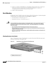
... at the bottom of the rack if it is the only unit in the rack. • When mounting this unit in a rack, you must take special precautions to ensure your safety: • This unit should be mounted at the bottom of the switch. Rack-Mounting Installing the Catalyst 3560-8PC switch or the Catalyst 3560 12-PC-S switch in the rack. Figure 3-8 Attaching the 19-inch...
... at the bottom of the rack if it is the only unit in the rack. • When mounting this unit in a rack, you must take special precautions to ensure your safety: • This unit should be mounted at the bottom of the switch. Rack-Mounting Installing the Catalyst 3560-8PC switch or the Catalyst 3560 12-PC-S switch in the rack. Figure 3-8 Attaching the 19-inch...

Hardware Installation Guide
Page 73
...-Port Switches) Installing the Switch Mounting the Switch in a 19-Inch Rack After the brackets are attached to one side of the switch and cables, make sure the switch is mounted in the rack. Power on the switch. To use the CLI setup program, see Appendix D, "Configuring the Switch with Rack-Mount Brackets) Installing the Catalyst 3560-8PC switch or the Catalyst 3560 12-PC-S switch in a 19-inch rack requires...
...-Port Switches) Installing the Switch Mounting the Switch in a 19-Inch Rack After the brackets are attached to one side of the switch and cables, make sure the switch is mounted in the rack. Power on the switch. To use the CLI setup program, see Appendix D, "Configuring the Switch with Rack-Mount Brackets) Installing the Catalyst 3560-8PC switch or the Catalyst 3560 12-PC-S switch in a 19-inch rack requires...
Hardware Installation Guide
Page 118
... cables four twisted-pair 1000BASE-T ports B-6 two twisted-pair B-5 PoE LED 1-13 shock hazard warning 2-4, 3-4 IN-4 Catalyst 3560 Switch Hardware Installation Guide port and interface troubleshooting 4-4 port LEDs 1-13 port modes changing 1-11 LEDs 1-13 See also Mode button... grounding C-2 to 2-15 installation (8- and 12-port switches) 3-7 to 2-10 rack-mount (24- and 12-port switches) 3-17 mounting desk- and 48-port switches) 2-10 rack-mount (8- and 48-port switches) 2-8 to 3-18 publications, related i-viii R rack-mounting OL-6337-07 Index mounting brackets attaching (24-
... cables four twisted-pair 1000BASE-T ports B-6 two twisted-pair B-5 PoE LED 1-13 shock hazard warning 2-4, 3-4 IN-4 Catalyst 3560 Switch Hardware Installation Guide port and interface troubleshooting 4-4 port LEDs 1-13 port modes changing 1-11 LEDs 1-13 See also Mode button... grounding C-2 to 2-15 installation (8- and 12-port switches) 3-7 to 2-10 rack-mount (24- and 12-port switches) 3-17 mounting desk- and 48-port switches) 2-10 rack-mount (8- and 48-port switches) 2-8 to 3-18 publications, related i-viii R rack-mounting OL-6337-07 Index mounting brackets attaching (24-