Hardware Installation Guide
Page 1
Catalyst 3560 Switch Hardware Installation Guide March 2010 Americas Headquarters Cisco Systems, Inc. 170 West Tasman Drive San Jose, CA 95134-1706 USA http://www.cisco.com Tel: 408 526-4000 800 553-NETS (6387) Fax: 408 527-0883 Text Part Number: OL-6337-07
Catalyst 3560 Switch Hardware Installation Guide March 2010 Americas Headquarters Cisco Systems, Inc. 170 West Tasman Drive San Jose, CA 95134-1706 USA http://www.cisco.com Tel: 408 526-4000 800 553-NETS (6387) Fax: 408 527-0883 Text Part Number: OL-6337-07
Hardware Installation Guide
Page 2
... is unintentional and coincidental. Changing the Way We Work, Live, Play, and Learn, Cisco Capital, Cisco Capital (Design), Cisco:Financed (Stylized), Cisco Store, Flip Gift Card, and One Million Acts of their own expense. Catalyst 3560 Switch Hardware Installation Guide © 2004-2010 Cisco Systems, Inc. IF YOU ARE UNABLE TO LOCATE THE SOFTWARE LICENSE OR LIMITED WARRANTY...
... is unintentional and coincidental. Changing the Way We Work, Live, Play, and Learn, Cisco Capital, Cisco Capital (Design), Cisco:Financed (Stylized), Cisco Store, Flip Gift Card, and One Million Acts of their own expense. Catalyst 3560 Switch Hardware Installation Guide © 2004-2010 Cisco Systems, Inc. IF YOU ARE UNABLE TO LOCATE THE SOFTWARE LICENSE OR LIMITED WARRANTY...

Hardware Installation Guide
Page 3
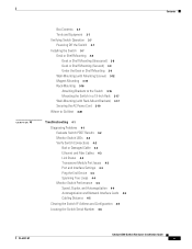
...Related Publications i-viii Obtaining Documentation and Submitting a Service Request i-ix Product Overview 1-1 Setting Up the Switch 1-1 Features 1-1 Front Panel Description 1-3 Fast Ethernet Switch Front Panel Descriptions 1-3 Gigabit Ethernet Switch Front Panel Descriptions 1-6 10/100 and 10/100/1000 Ports 1-8 PoE Ports 1-9 SFP Module ... Guard 1-15 Rear Panel Description 1-15 Internal Power Supply 1-18 DC Power Connector 1-18 Cisco RPS 1-19 Cisco RPS 2300 1-19 Cisco RPS 675 1-19 Console Port 1-19 Security Slots 1-20 Management Options 1-20 Catalyst 3560 Switch Hardware Installation Guide iii
...Related Publications i-viii Obtaining Documentation and Submitting a Service Request i-ix Product Overview 1-1 Setting Up the Switch 1-1 Features 1-1 Front Panel Description 1-3 Fast Ethernet Switch Front Panel Descriptions 1-3 Gigabit Ethernet Switch Front Panel Descriptions 1-6 10/100 and 10/100/1000 Ports 1-8 PoE Ports 1-9 SFP Module ... Guard 1-15 Rear Panel Description 1-15 Internal Power Supply 1-18 DC Power Connector 1-18 Cisco RPS 1-19 Cisco RPS 2300 1-19 Cisco RPS 675 1-19 Console Port 1-19 Security Slots 1-20 Management Options 1-20 Catalyst 3560 Switch Hardware Installation Guide iii

Hardware Installation Guide
Page 4
... Modules into SFP Module Slots 2-16 Removing SFP Modules from the Switch 2-8 Attaching Brackets to the Catalyst 3560 Switch 2-8 Mounting the Switch in a Rack 2-10 Attaching the Cable Guide 2-11 Wall-Mounting 2-12 Attaching the Brackets to Go Next 2-24 Switch Installation (8- and 12-Port Switches) 3-1 Preparing for Wall Mounting 2-12 Attaching the RPS Connector Cover 2-13...
... Modules into SFP Module Slots 2-16 Removing SFP Modules from the Switch 2-8 Attaching Brackets to the Catalyst 3560 Switch 2-8 Mounting the Switch in a Rack 2-10 Attaching the Cable Guide 2-11 Wall-Mounting 2-12 Attaching the Brackets to Go Next 2-24 Switch Installation (8- and 12-Port Switches) 3-1 Preparing for Wall Mounting 2-12 Attaching the RPS Connector Cover 2-13...
Hardware Installation Guide
Page 5
... the AC Power Cord 3-19 Where to Go Next 3-20 Troubleshooting 4-1 Diagnosing Problems 4-1 Evaluate Switch POST Results 4-2 Monitor Switch LEDs 4-2 Verify Switch Connections 4-2 Bad or Damaged Cable 4-2 Ethernet and Fiber Cables 4-3 Link Status 4-3 Transceiver Module ... 4-4 Spanning Tree Loops 4-4 Monitor Switch Performance 4-4 Speed, Duplex, and Autonegotiation 4-4 Autonegotiation and Network Interface Cards 4-5 Cabling Distance 4-5 Clearing the Switch IP Address and Configuration 4-5 Locating the Switch Serial Number 4-6 Contents OL-6337-07 Catalyst 3560 Switch Hardware Installation Guide v
... the AC Power Cord 3-19 Where to Go Next 3-20 Troubleshooting 4-1 Diagnosing Problems 4-1 Evaluate Switch POST Results 4-2 Monitor Switch LEDs 4-2 Verify Switch Connections 4-2 Bad or Damaged Cable 4-2 Ethernet and Fiber Cables 4-3 Link Status 4-3 Transceiver Module ... 4-4 Spanning Tree Loops 4-4 Monitor Switch Performance 4-4 Speed, Duplex, and Autonegotiation 4-4 Autonegotiation and Network Interface Cards 4-5 Cabling Distance 4-5 Clearing the Switch IP Address and Configuration 4-5 Locating the Switch Serial Number 4-6 Contents OL-6337-07 Catalyst 3560 Switch Hardware Installation Guide v

Hardware Installation Guide
Page 6
... Pinouts for 1000BASE-T Ports B-6 Identifying a Crossover Cable B-6 Adapter Pinouts B-7 Connecting to DC Power C-1 Connecting to DC Power C-1 Preparing for Installation C-2 Grounding the Switch C-2 Wiring the DC-Input Power Source C-5 Configuring the Switch with the CLI-Based Setup Program D-1 Preparing for Setup D-1 Completing the Setup Program D-3 Catalyst 3560 Switch Hardware Installation Guide vi OL-6337-07
... Pinouts for 1000BASE-T Ports B-6 Identifying a Crossover Cable B-6 Adapter Pinouts B-7 Connecting to DC Power C-1 Connecting to DC Power C-1 Preparing for Installation C-2 Grounding the Switch C-2 Wiring the DC-Input Power Source C-5 Configuring the Switch with the CLI-Based Setup Program D-1 Preparing for Setup D-1 Completing the Setup Program D-3 Catalyst 3560 Switch Hardware Installation Guide vi OL-6337-07
Hardware Installation Guide
Page 7
... training and education in equipment damage or loss of the Catalyst 3560 switch. For information about the standard Cisco IOS Release 12.2 commands, see the switch software configuration guide, the switch command reference, and the switch system message guide on the Cisco Training & Events web page: http://www.cisco.com/web/learning/index.html Purpose This guide describes the...
... training and education in equipment damage or loss of the Catalyst 3560 switch. For information about the standard Cisco IOS Release 12.2 commands, see the switch software configuration guide, the switch command reference, and the switch system message guide on the Cisco Training & Events web page: http://www.cisco.com/web/learning/index.html Purpose This guide describes the...
Hardware Installation Guide
Page 8
... information about related products, see the release notes on Cisco.com for the latest information. • Catalyst 3560 Switch Software Configuration Guide • Catalyst 3560 Switch Command Reference • Catalyst 3750, 3560, 3550, 2970, and 2960 Switch System Message Guide • Catalyst 3560 Switch Getting Started Guide • Regulatory Compliance and Safety Information for the Catalyst 3560 Switch • Device manager online help (available on the...
... information about related products, see the release notes on Cisco.com for the latest information. • Catalyst 3560 Switch Software Configuration Guide • Catalyst 3560 Switch Command Reference • Catalyst 3750, 3560, 3550, 2970, and 2960 Switch System Message Guide • Catalyst 3560 Switch Getting Started Guide • Regulatory Compliance and Safety Information for the Catalyst 3560 Switch • Device manager online help (available on the...
Hardware Installation Guide
Page 9
OL-6337-07 Catalyst 3560 Switch Hardware Installation Guide ix The RSS feeds are a free service and Cisco currently supports RSS version 2.0. Preface Obtaining Documentation and Submitting a Service Request • Cisco Small Form-Factor Pluggable Modules Compatibility Matrix • Compatibility Matrix for 1000BASE-T... request, and gathering additional information, see the monthly What's New in Cisco Product Documentation, which also lists all new and revised Cisco technical documentation, at: http://www.cisco.com/en/US/docs/general/whatsnew/whatsnew.html Subscribe to the What's New...
OL-6337-07 Catalyst 3560 Switch Hardware Installation Guide ix The RSS feeds are a free service and Cisco currently supports RSS version 2.0. Preface Obtaining Documentation and Submitting a Service Request • Cisco Small Form-Factor Pluggable Modules Compatibility Matrix • Compatibility Matrix for 1000BASE-T... request, and gathering additional information, see the monthly What's New in Cisco Product Documentation, which also lists all new and revised Cisco technical documentation, at: http://www.cisco.com/en/US/docs/general/whatsnew/whatsnew.html Subscribe to the What's New...
Hardware Installation Guide
Page 10
Obtaining Documentation and Submitting a Service Request Preface Catalyst 3560 Switch Hardware Installation Guide x OL-6337-07
Obtaining Documentation and Submitting a Service Request Preface Catalyst 3560 Switch Hardware Installation Guide x OL-6337-07

Hardware Installation Guide
Page 11
...-swappable. Features The 24- and 12-port switches include connections for instructions on setting up your Catalyst switch. For instructions on how to use Express Setup to the switches. and 48-port Catalyst 3560 switches can be deployed as servers, routers, and other network devices. The Catalyst 3560-8PC and the Catalyst 3560-12PC-S compact switches provide the same Power over Ethernet (PoE...
...-swappable. Features The 24- and 12-port switches include connections for instructions on setting up your Catalyst switch. For instructions on how to use Express Setup to the switches. and 48-port Catalyst 3560 switches can be deployed as servers, routers, and other network devices. The Catalyst 3560-8PC and the Catalyst 3560-12PC-S compact switches provide the same Power over Ethernet (PoE...

Hardware Installation Guide
Page 12
... patch cable. (CAB-SFP-50CM=.) Switches running Cisco IOS Release 12.2(25)SEB or later support this patch cable. and 12-port switches) • 100BASE-FX • 100BASE-LX (only Catalyst 3560 8- The Catalyst 3560-8PC and the Catalyst 3560-12PC-S switches are smaller than the other Catalyst 3560 switches. Supported SFP modules: • 100BASE-BX10 (only Catalyst 3560 8- and 12-port switches) • 1000BASE-BX10 •...
... patch cable. (CAB-SFP-50CM=.) Switches running Cisco IOS Release 12.2(25)SEB or later support this patch cable. and 12-port switches) • 100BASE-FX • 100BASE-LX (only Catalyst 3560 8- The Catalyst 3560-8PC and the Catalyst 3560-12PC-S switches are smaller than the other Catalyst 3560 switches. Supported SFP modules: • 100BASE-BX10 (only Catalyst 3560 8- and 12-port switches) • 1000BASE-BX10 •...

Hardware Installation Guide
Page 13
...duplex settings are numbered 1 and 2. Figure 1-1 Catalyst 3560-24PS and 3560V2-24PS Switch Front Panel OL-6337-07 97912 SYST RPS ...Catalyst 3560-24PS and 3560V2-24PS Switch Front Panel, Figure 1-1 on page 1-3 • Catalyst 3560-24TS-S, 3560V2-24TS, and 3560V2-24TS-SD Switch Front Panel, Figure 1-2 on page 1-4 • Catalyst 3560-48PS and 3560V2-48PS Switch Front Panel, Figure 1-3 on page 1-4 • Catalyst 3560-48TS-S and 3560V2-48TS Switch Front Panel, Figure 1-4 on page 1-5 • Catalyst 3560-8PC Switch Front Panel, Figure 1-5 on page 1-5 • Catalyst 3560-12PC-S Switch...
...duplex settings are numbered 1 and 2. Figure 1-1 Catalyst 3560-24PS and 3560V2-24PS Switch Front Panel OL-6337-07 97912 SYST RPS ...Catalyst 3560-24PS and 3560V2-24PS Switch Front Panel, Figure 1-1 on page 1-3 • Catalyst 3560-24TS-S, 3560V2-24TS, and 3560V2-24TS-SD Switch Front Panel, Figure 1-2 on page 1-4 • Catalyst 3560-48PS and 3560V2-48PS Switch Front Panel, Figure 1-3 on page 1-4 • Catalyst 3560-48TS-S and 3560V2-48TS Switch Front Panel, Figure 1-4 on page 1-5 • Catalyst 3560-8PC Switch Front Panel, Figure 1-5 on page 1-5 • Catalyst 3560-12PC-S Switch...

Hardware Installation Guide
Page 14
... to 4. The first member of the pair (port 1) is above the second member (port 2) on the left , as shown in Figure 1-2. Figure 1-3 Catalyst 3560-48PS and 3560V2-48PS Switch Front Panel 97911 SYST RPS STAT DUPLX SPEED PoE MODE 1 1X 2X 23 45 67 8 9 10 11 12 13 14 15 16 17...33 31X 33X 34 35 36 37 38 39 40 41 42 43 44 45 46 47 48 Catalyst 3560 SERIES PoE-48 47X 32X 34X 1 3 48X 2 4 1 2 1 10/100 PoE ports 2 SFP module slots Catalyst 3560 Switch Hardware Installation Guide 1-4 OL-6337-07 Front Panel Description Chapter 1 Product Overview The 10/100 ports...
... to 4. The first member of the pair (port 1) is above the second member (port 2) on the left , as shown in Figure 1-2. Figure 1-3 Catalyst 3560-48PS and 3560V2-48PS Switch Front Panel 97911 SYST RPS STAT DUPLX SPEED PoE MODE 1 1X 2X 23 45 67 8 9 10 11 12 13 14 15 16 17...33 31X 33X 34 35 36 37 38 39 40 41 42 43 44 45 46 47 48 Catalyst 3560 SERIES PoE-48 47X 32X 34X 1 3 48X 2 4 1 2 1 10/100 PoE ports 2 SFP module slots Catalyst 3560 Switch Hardware Installation Guide 1-4 OL-6337-07 Front Panel Description Chapter 1 Product Overview The 10/100 ports...

Hardware Installation Guide
Page 15
...port, see the "Console Port" section on page 1-10. The SFP module slots are on . Figure 1-5 Catalyst 3560-8PC Switch Front Panel SYST STAT DPLX SPD MODE CONSOLE 1x 2x 3x 4x 5x 6x 7x 8x Catalyst 2960 Series 1 157822 1 2 3 1 Console port 2 10/100 PoE ports 3 Dual-purpose port OL... an RJ-45 connector or an SFP module, but not both at the same time. The first member of the Catalyst 3560-8PC switch and the Catalyst 3560-12PC-S switch (Figure 1-5 and Figure 1-6). Chapter 1 Product Overview Front Panel Description The 10/100 ports on the left, as shown in pairs....
...port, see the "Console Port" section on page 1-10. The SFP module slots are on . Figure 1-5 Catalyst 3560-8PC Switch Front Panel SYST STAT DPLX SPD MODE CONSOLE 1x 2x 3x 4x 5x 6x 7x 8x Catalyst 2960 Series 1 157822 1 2 3 1 Console port 2 10/100 PoE ports 3 Dual-purpose port OL... an RJ-45 connector or an SFP module, but not both at the same time. The first member of the Catalyst 3560-8PC switch and the Catalyst 3560-12PC-S switch (Figure 1-5 and Figure 1-6). Chapter 1 Product Overview Front Panel Description The 10/100 ports on the left, as shown in pairs....

Hardware Installation Guide
Page 16
... 9 10 11 12 1 2 Catalyst 3560 SERIESPoE-12 1 3 1 Console port 2 10/100 PoE ports 3 Dual-purpose port Gigabit Ethernet Switch Front Panel Descriptions • Catalyst 3560G-24PS Switch Front Panel, Figure 1-7 on page 1-6 • Catalyst 3560G-24TS Switch Front Panel, Figure 1-8 on page 1-7 • Catalyst 3560G-48PS Switch Front Panel, Figure 1-9 on page 1-7 • Catalyst 3560G-48TS Switch Front Panel, Figure 1-10...
... 9 10 11 12 1 2 Catalyst 3560 SERIESPoE-12 1 3 1 Console port 2 10/100 PoE ports 3 Dual-purpose port Gigabit Ethernet Switch Front Panel Descriptions • Catalyst 3560G-24PS Switch Front Panel, Figure 1-7 on page 1-6 • Catalyst 3560G-24TS Switch Front Panel, Figure 1-8 on page 1-7 • Catalyst 3560G-48PS Switch Front Panel, Figure 1-9 on page 1-7 • Catalyst 3560G-48TS Switch Front Panel, Figure 1-10...

Hardware Installation Guide
Page 17
...35 36 37 38 39 40 41 42 43 44 45 46 47 48 Catalyst 3560G SERIES PoE-48 47X 32X 34X 49 51 48X 50 52 1 2 1 10/100/1000 ports 2 SFP module slots OL-6337-07 Catalyst 3560 Switch Hardware Installation Guide 1-7 Port 3 is above port 4, and so on .... The first member of the pair (port 1) is above the second member (port 2) on the Catalyst 3560G-48PS switch are numbered 25 to 52. Chapter 1 Product Overview Front Panel ...
...35 36 37 38 39 40 41 42 43 44 45 46 47 48 Catalyst 3560G SERIES PoE-48 47X 32X 34X 49 51 48X 50 52 1 2 1 10/100/1000 ports 2 SFP module slots OL-6337-07 Catalyst 3560 Switch Hardware Installation Guide 1-7 Port 3 is above port 4, and so on .... The first member of the pair (port 1) is above the second member (port 2) on the Catalyst 3560G-48PS switch are numbered 25 to 52. Chapter 1 Product Overview Front Panel ...

Hardware Installation Guide
Page 18
.... Avoid using uninsulated exposed metal contacts, conductors, or terminals. Front Panel Description Chapter 1 Product Overview The 10/100/1000 ports on the Catalyst 3560G-48TS switch are numbered 49 to 52. Port 3 is autonegotiate.) • You can set to 10 or 100 Mb/s. In all cases, the ... setting is above the second member (port 2) on the left, as shown in pairs. The SFP module slots are grouped in Figure 1-10. Catalyst 3560 Switch Hardware Installation Guide 1-8 OL-6337-07 A restricted access area can use of a special tool, lock and key or other means of the attached ...
.... Avoid using uninsulated exposed metal contacts, conductors, or terminals. Front Panel Description Chapter 1 Product Overview The 10/100/1000 ports on the Catalyst 3560G-48TS switch are numbered 49 to 52. Port 3 is autonegotiate.) • You can set to 10 or 100 Mb/s. In all cases, the ... setting is above the second member (port 2) on the left, as shown in pairs. The SFP module slots are grouped in Figure 1-10. Catalyst 3560 Switch Hardware Installation Guide 1-8 OL-6337-07 A restricted access area can use of a special tool, lock and key or other means of the attached ...

Hardware Installation Guide
Page 19
... configuration guide. When using a straight-through cable. The Auto setting is connected. • You can connect a Cisco IP Phone or Cisco Aironet Access Point to a Catalyst 3560 PoE switch 10/100 or 10/100/1000 port and to an AC power source for the cables are described in Appendix ... that case, the PoE port becomes the backup power source for Cisco IP Phones and Cisco Aironet Access Points. • Each of the Catalyst 3560-8PC, 3560-12PC-S, 3560-24PS, and 3560V2-24PS switch 10/100 ports or the Catalyst 3560G-24PS switch 10/100/1000 ports deliver up to a maximum power output of...
... configuration guide. When using a straight-through cable. The Auto setting is connected. • You can connect a Cisco IP Phone or Cisco Aironet Access Point to a Catalyst 3560 PoE switch 10/100 or 10/100/1000 port and to an AC power source for the cables are described in Appendix ... that case, the PoE port becomes the backup power source for Cisco IP Phones and Cisco Aironet Access Points. • Each of the Catalyst 3560-8PC, 3560-12PC-S, 3560-24PS, and 3560V2-24PS switch 10/100 ports or the Catalyst 3560G-24PS switch 10/100/1000 ports deliver up to a maximum power output of...

Hardware Installation Guide
Page 20
...10/100/1000 port or as a single interface with LC or MT-RJ connectors to connect to other Catalyst series switches, you can connect only two Catalyst 3560 switches. By default, the switch dynamically selects the interface type that do not fully support IEEE 802.3af, might not support PoE when ...module patch cable. Front Panel Description Chapter 1 Product Overview Many legacy powered devices, including older Cisco IP phones and access points that first links up. SFP Modules The switch uses Gigabit Ethernet SFP modules to select the RJ-45 connector or the SFP module connector. ...
...10/100/1000 port or as a single interface with LC or MT-RJ connectors to connect to other Catalyst series switches, you can connect only two Catalyst 3560 switches. By default, the switch dynamically selects the interface type that do not fully support IEEE 802.3af, might not support PoE when ...module patch cable. Front Panel Description Chapter 1 Product Overview Many legacy powered devices, including older Cisco IP phones and access points that first links up. SFP Modules The switch uses Gigabit Ethernet SFP modules to select the RJ-45 connector or the SFP module connector. ...

