
Hardware Installation Guide
Page 3
... 1-1 Front Panel Description 1-3 Fast Ethernet Switch Front Panel Descriptions 1-3 Gigabit Ethernet Switch Front Panel Descriptions 1-6 10/100 and 10/100/1000 Ports 1-8 PoE Ports 1-9 SFP Module Slots 1-10 SFP Modules 1-10 SFP Module Patch Cable 1-10 Dual-Purpose Port 1-10 LEDs 1-11 System LED 1-11 RPS LED... Dual-Purpose Port LEDs 1-15 Cable Guard 1-15 Rear Panel Description 1-15 Internal Power Supply 1-18 DC Power Connector 1-18 Cisco RPS 1-19 Cisco RPS 2300 1-19 Cisco RPS 675 1-19 Console Port 1-19 Security Slots 1-20 Management Options 1-20 Catalyst 3560 Switch Hardware Installation Guide iii
... 1-1 Front Panel Description 1-3 Fast Ethernet Switch Front Panel Descriptions 1-3 Gigabit Ethernet Switch Front Panel Descriptions 1-6 10/100 and 10/100/1000 Ports 1-8 PoE Ports 1-9 SFP Module Slots 1-10 SFP Modules 1-10 SFP Module Patch Cable 1-10 Dual-Purpose Port 1-10 LEDs 1-11 System LED 1-11 RPS LED... Dual-Purpose Port LEDs 1-15 Cable Guard 1-15 Rear Panel Description 1-15 Internal Power Supply 1-18 DC Power Connector 1-18 Cisco RPS 1-19 Cisco RPS 2300 1-19 Cisco RPS 675 1-19 Console Port 1-19 Security Slots 1-20 Management Options 1-20 Catalyst 3560 Switch Hardware Installation Guide iii

Hardware Installation Guide
Page 11
... Catalyst 3560-8PC and the Catalyst 3560-12PC-S compact switches provide the same Power over Ethernet (PoE) connectivity and can connect devices like workstations, Cisco Wireless Access Points, Cisco IP Phones, and other network devices such as servers, routers, and other network devices. See the... switch software configuration guide for an optional Cisco RPS 2300 or Cisco RPS 675 that operates on AC power and supplies backup DC power to the switches. This chapter provides a functional overview...
... Catalyst 3560-8PC and the Catalyst 3560-12PC-S compact switches provide the same Power over Ethernet (PoE) connectivity and can connect devices like workstations, Cisco Wireless Access Points, Cisco IP Phones, and other network devices such as servers, routers, and other network devices. See the... switch software configuration guide for an optional Cisco RPS 2300 or Cisco RPS 675 that operates on AC power and supplies backup DC power to the switches. This chapter provides a functional overview...

Hardware Installation Guide
Page 12
... and 4 SFP module slots Catalyst 3560V2-48TS 48 10/100 ports and 4 SFP module slots Catalyst 3560V2-24TS-SD 24 10/100 PoE ports and 2 SFP module slots (DC power) Catalyst 3560-8PC1 8 10/100 PoE ports and 1 dual-purpose port (one 10/100/1000BASE-T copper port and one SFP module slot) Catalyst... Catalyst 3560 8- and 48-port switches) • 1000BASE-ZX • Coarse Wavelength-Division Multiplexing (CWDM) • SFP module patch cable. (CAB-SFP-50CM=.) Switches running Cisco IOS Release 12.2(25)SEB or later support this patch cable.
... and 4 SFP module slots Catalyst 3560V2-48TS 48 10/100 ports and 4 SFP module slots Catalyst 3560V2-24TS-SD 24 10/100 PoE ports and 2 SFP module slots (DC power) Catalyst 3560-8PC1 8 10/100 PoE ports and 1 dual-purpose port (one 10/100/1000BASE-T copper port and one SFP module slot) Catalyst... Catalyst 3560 8- and 48-port switches) • 1000BASE-ZX • Coarse Wavelength-Division Multiplexing (CWDM) • SFP module patch cable. (CAB-SFP-50CM=.) Switches running Cisco IOS Release 12.2(25)SEB or later support this patch cable.

Hardware Installation Guide
Page 13
... Panel Descriptions, page 1-3 • Gigabit Ethernet Switch Front Panel Descriptions, page 1-6 • 10/100 and 10/100/1000 Ports, page 1-8 • PoE Ports, page 1-9 • SFP Module Slots, page 1-10 • Dual-Purpose Port, page 1-10 • LEDs, page 1-11 • Cable ...Ethernet Switch Front Panel Descriptions • Catalyst 3560-24PS and 3560V2-24PS Switch Front Panel, Figure 1-1 on page 1-3 • Catalyst 3560-24TS-S, 3560V2-24TS, and 3560V2-24TS-SD Switch Front Panel, Figure 1-2 on page 1-4 • Catalyst 3560-48PS and 3560V2-48PS Switch Front Panel, Figure 1-3 on page...
... Panel Descriptions, page 1-3 • Gigabit Ethernet Switch Front Panel Descriptions, page 1-6 • 10/100 and 10/100/1000 Ports, page 1-8 • PoE Ports, page 1-9 • SFP Module Slots, page 1-10 • Dual-Purpose Port, page 1-10 • LEDs, page 1-11 • Cable ...Ethernet Switch Front Panel Descriptions • Catalyst 3560-24PS and 3560V2-24PS Switch Front Panel, Figure 1-1 on page 1-3 • Catalyst 3560-24TS-S, 3560V2-24TS, and 3560V2-24TS-SD Switch Front Panel, Figure 1-2 on page 1-4 • Catalyst 3560-48PS and 3560V2-48PS Switch Front Panel, Figure 1-3 on page...

Hardware Installation Guide
Page 14
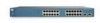
... Catalyst 3560-48PS and 3560V2-48PS Switch Front Panel 97911 SYST RPS STAT DUPLX SPEED PoE MODE 1 1X 2X 23 45 67 8 9 10 11 12 13 14 15 16...member (port 2) on the switch are numbered 1 to 4. Figure 1-2 Catalyst 3560-24TS-S, 3560V2-24TS, and 3560V2-24TS-SD Switch Front Panel 126808 SYST RPS STAT DUPLX SPEED MODE 12 1X 34 56... 78 9 10 11 12 11X 2X 12X 13 14 13X 15 16 17 18 19 20 21 22 23 24 23X Catalyst 3560 SERIES 14X 24X 1 2 1 2 1 10/100 ports 2 SFP module slots The 10/100 PoE...
... Catalyst 3560-48PS and 3560V2-48PS Switch Front Panel 97911 SYST RPS STAT DUPLX SPEED PoE MODE 1 1X 2X 23 45 67 8 9 10 11 12 13 14 15 16...member (port 2) on the switch are numbered 1 to 4. Figure 1-2 Catalyst 3560-24TS-S, 3560V2-24TS, and 3560V2-24TS-SD Switch Front Panel 126808 SYST RPS STAT DUPLX SPEED MODE 12 1X 34 56... 78 9 10 11 12 11X 2X 12X 13 14 13X 15 16 17 18 19 20 21 22 23 24 23X Catalyst 3560 SERIES 14X 24X 1 2 1 2 1 10/100 ports 2 SFP module slots The 10/100 PoE...

Hardware Installation Guide
Page 15
...42 43 44 45 46 47 48 47X 32X 34X Catalyst 3560 SERIES 1 3 48X 2 4 1 2 1 10/100 ports 2 SFP module slots The console port, 10/100 PoE ports, and a dual-purpose port are on the front panel of the pair (port 1) is above the second member (port 2) on the left, as shown... Switch Front Panel SYST STAT DPLX SPD MODE CONSOLE 1x 2x 3x 4x 5x 6x 7x 8x Catalyst 2960 Series 1 157822 1 2 3 1 Console port 2 10/100 PoE ports 3 Dual-purpose port OL-6337-07 Catalyst 3560 Switch Hardware Installation Guide 1-5 The SFP module slots are numbered 1 to 4. The first member of the...
...42 43 44 45 46 47 48 47X 32X 34X Catalyst 3560 SERIES 1 3 48X 2 4 1 2 1 10/100 ports 2 SFP module slots The console port, 10/100 PoE ports, and a dual-purpose port are on the front panel of the pair (port 1) is above the second member (port 2) on the left, as shown... Switch Front Panel SYST STAT DPLX SPD MODE CONSOLE 1x 2x 3x 4x 5x 6x 7x 8x Catalyst 2960 Series 1 157822 1 2 3 1 Console port 2 10/100 PoE ports 3 Dual-purpose port OL-6337-07 Catalyst 3560 Switch Hardware Installation Guide 1-5 The SFP module slots are numbered 1 to 4. The first member of the...

Hardware Installation Guide
Page 16
... 1 2 Catalyst 3560 SERIESPoE-12 1 3 1 Console port 2 10/100 PoE ports 3 Dual-purpose port Gigabit Ethernet Switch Front Panel Descriptions • Catalyst 3560G-24PS Switch Front Panel, Figure 1-7 on page 1-6 • Catalyst 3560G-24TS Switch Front Panel, Figure 1-8 on page 1-7 • Catalyst 3560G-48PS Switch... Front Panel, Figure 1-9 on page 1-7 • Catalyst 3560G-48TS Switch Front Panel, Figure 1-10 on page 1-8 The 10/100/1000 PoE ports on the Catalyst 3560G-24PS ...
... 1 2 Catalyst 3560 SERIESPoE-12 1 3 1 Console port 2 10/100 PoE ports 3 Dual-purpose port Gigabit Ethernet Switch Front Panel Descriptions • Catalyst 3560G-24PS Switch Front Panel, Figure 1-7 on page 1-6 • Catalyst 3560G-24TS Switch Front Panel, Figure 1-8 on page 1-7 • Catalyst 3560G-48PS Switch... Front Panel, Figure 1-9 on page 1-7 • Catalyst 3560G-48TS Switch Front Panel, Figure 1-10 on page 1-8 The 10/100/1000 PoE ports on the Catalyst 3560G-24PS ...

Hardware Installation Guide
Page 17
..., as shown in Figure 1-8. Figure 1-9 Catalyst 3560G-48PS Switch Front Panel 119674 SYST RPS STAT DUPLX SPEED PoE MODE 1 1X 2X 23 45 67 8 9 10 11 12 13 14 15 16 17 15X 17X 18...1000 ports 2 SFP module slots OL-6337-07 Catalyst 3560 Switch Hardware Installation Guide 1-7 Figure 1-8 Catalyst 3560G-24TS Switch Front Panel 119677 SYST RPS STAT DUPLX SPEED MODE 12 1X 34 56 78 9 10 11 12 ...14X 27 24X 26 28 1 2 1 10/100/1000 ports 2 SFP module slots The 10/100/1000 PoE ports on the Catalyst 3560G-48PS switch are grouped in pairs. The first member of the pair (port 1)...
..., as shown in Figure 1-8. Figure 1-9 Catalyst 3560G-48PS Switch Front Panel 119674 SYST RPS STAT DUPLX SPEED PoE MODE 1 1X 2X 23 45 67 8 9 10 11 12 13 14 15 16 17 15X 17X 18...1000 ports 2 SFP module slots OL-6337-07 Catalyst 3560 Switch Hardware Installation Guide 1-7 Figure 1-8 Catalyst 3560G-24TS Switch Front Panel 119677 SYST RPS STAT DUPLX SPEED MODE 12 1X 34 56 78 9 10 11 12 ...14X 27 24X 26 28 1 2 1 10/100/1000 ports 2 SFP module slots The 10/100/1000 PoE ports on the Catalyst 3560G-48PS switch are grouped in pairs. The first member of the pair (port 1)...

Hardware Installation Guide
Page 18
... device also supports autonegotiation, the switch port negotiates the best connection (the fastest line speed that present a shock hazard may exist on Power over Ethernet (PoE) circuits if interconnections are numbered 49 to operate at 10 or 100 Mb/s in half or full duplex or at 1000 Mb/s in pairs. Catalyst...
... device also supports autonegotiation, the switch port negotiates the best connection (the fastest line speed that present a shock hazard may exist on Power over Ethernet (PoE) circuits if interconnections are numbered 49 to operate at 10 or 100 Mb/s in half or full duplex or at 1000 Mb/s in pairs. Catalyst...

Hardware Installation Guide
Page 19
... 3560-12PC-S switch delivers a maximum power output of approximately 125 W total PoE power. • On a per-port basis, you can connect a Cisco IP Phone or Cisco Aironet Access Point to a Catalyst 3560 PoE switch 10/100 or 10/100/1000 port and to an AC power source... 5 cable for proper operation. The device manager, Network Assistant, and the CLI provide PoE settings for copper Ethernet connections and configures the interfaces accordingly. For configuration information for Cisco IP Phones and Cisco Aironet Access Points. • Each of the Catalyst 3560-8PC, 3560-12PC-S, 3560-...
... 3560-12PC-S switch delivers a maximum power output of approximately 125 W total PoE power. • On a per-port basis, you can connect a Cisco IP Phone or Cisco Aironet Access Point to a Catalyst 3560 PoE switch 10/100 or 10/100/1000 port and to an AC power source... 5 cable for proper operation. The device manager, Network Assistant, and the CLI provide PoE settings for copper Ethernet connections and configures the interfaces accordingly. For configuration information for Cisco IP Phones and Cisco Aironet Access Points. • Each of the Catalyst 3560-8PC, 3560-12PC-S, 3560-...

Hardware Installation Guide
Page 20
...of supported SFP modules. By default, the switch dynamically selects the interface type that do not fully support IEEE 802.3af, might not support PoE when connected to a copper SFP module. SFP Module Patch Cable The switch supports the SFP module patch cable (CAB-SFP-50CM=), a 0.5...module patch cable can connect only two Catalyst 3560 switches. Front Panel Description Chapter 1 Product Overview Many legacy powered devices, including older Cisco IP phones and access points that first links up. SFP Modules The switch uses Gigabit Ethernet SFP modules to a fiber-optic SFP module...
...of supported SFP modules. By default, the switch dynamically selects the interface type that do not fully support IEEE 802.3af, might not support PoE when connected to a copper SFP module. SFP Module Patch Cable The switch supports the SFP module patch cable (CAB-SFP-50CM=), a 0.5...module patch cable can connect only two Catalyst 3560 switches. Front Panel Description Chapter 1 Product Overview Many legacy powered devices, including older Cisco IP phones and access points that first links up. SFP Modules The switch uses Gigabit Ethernet SFP modules to a fiber-optic SFP module...

Hardware Installation Guide
Page 21
... LED colors during the power-on self-test (POST), see the "Verifying Switch Operation" section on the Catalyst 3560 PoE switches. 2. Figure 1-12 shows the switch LEDs and the Mode button that you use the switch LEDs to monitor ...not powered on. Figure 1-12 Catalyst 3560 Switch LEDs SYST RPS STAT DUPLX SPEED PoE MODE 12345 67 8 12 1X 34 56 78 9 10 11 12 11X 2X 12X 97913 System LED 1 Mode... button 2 PoE LED1 5 Status LED 6 RPS LED2 3 Speed LED 7 System LED 4 Duplex LED 8 Port LEDs 1. System ...
... LED colors during the power-on self-test (POST), see the "Verifying Switch Operation" section on the Catalyst 3560 PoE switches. 2. Figure 1-12 shows the switch LEDs and the Mode button that you use the switch LEDs to monitor ...not powered on. Figure 1-12 Catalyst 3560 Switch LEDs SYST RPS STAT DUPLX SPEED PoE MODE 12345 67 8 12 1X 34 56 78 9 10 11 12 11X 2X 12X 97913 System LED 1 Mode... button 2 PoE LED1 5 Status LED 6 RPS LED2 3 Speed LED 7 System LED 4 Duplex LED 8 Port LEDs 1. System ...

Hardware Installation Guide
Page 23
...SPEED Port duplex mode Port speed The port duplex mode: full duplex or half duplex. None of the 10/100 or 10/100/1000 PoE ports have been denied power or are detected. OL-6337-07 Catalyst 3560 Switch Hardware Installation Guide 1-13 Chapter 1 Product Overview Front ...The port operating speed: 10, 100, or 10001 Mb/s. PoE PoE port power The PoE status. 1. Table 1-6 explains how to Catalyst 3560 switches that support PoE. Even if the PoE mode is highlighted. PoE mode is selected, and the PoE status is not selected. PoE mode is shown on the port LEDs. When installed in ...
...SPEED Port duplex mode Port speed The port duplex mode: full duplex or half duplex. None of the 10/100 or 10/100/1000 PoE ports have been denied power or are detected. OL-6337-07 Catalyst 3560 Switch Hardware Installation Guide 1-13 Chapter 1 Product Overview Front ...The port operating speed: 10, 100, or 10001 Mb/s. PoE PoE port power The PoE status. 1. Table 1-6 explains how to Catalyst 3560 switches that support PoE. Even if the PoE mode is highlighted. PoE mode is selected, and the PoE status is not selected. PoE mode is shown on the port LEDs. When installed in ...

Hardware Installation Guide
Page 24
... connected to 30 seconds as excessive collisions, cyclic redundancy check (CRC) errors, and alignment and jabber errors are connected to a fault. Amber PoE for possible loops. Error frames can remain amber for a link-fault indication. Blinking amber Port is blocked by Spanning Tree Protocol (STP) and...or 100 Mb/s in Different Modes on . Note When installed in Catalyst 3560 switches, 1000BASE-T SFP modules can be used to connect Cisco prestandard IP Phones or wireless access points or IEEE 802.3af-compliant devices to the powered device will exceed the 370 W switch power ...
... connected to 30 seconds as excessive collisions, cyclic redundancy check (CRC) errors, and alignment and jabber errors are connected to a fault. Amber PoE for possible loops. Error frames can remain amber for a link-fault indication. Blinking amber Port is blocked by Spanning Tree Protocol (STP) and...or 100 Mb/s in Different Modes on . Note When installed in Catalyst 3560 switches, 1000BASE-T SFP modules can be used to connect Cisco prestandard IP Phones or wireless access points or IEEE 802.3af-compliant devices to the powered device will exceed the 370 W switch power ...

Hardware Installation Guide
Page 36
... Catalyst 3560 Switch Hardware Installation Guide 2-4 OL-6337-07 Contact the appropriate electrical inspection authority or an electrician if you work on Power over Ethernet (PoE) circuits if interconnections are made aware of this equipment. Statement 1040 Warning For connections outside the building where the equipment is available. Use the statement...
... Catalyst 3560 Switch Hardware Installation Guide 2-4 OL-6337-07 Contact the appropriate electrical inspection authority or an electrician if you work on Power over Ethernet (PoE) circuits if interconnections are made aware of this equipment. Statement 1040 Warning For connections outside the building where the equipment is available. Use the statement...

Hardware Installation Guide
Page 37
... page B-4, which lists the cable specifications for 1000BASE-X and 100BASE-X SFP modules for Installation Caution To comply with the Telcordia GR-1089 NEBS standard, PoE or non-PoE 10/100/1000 Ethernet port cables that might damage the cables. • For copper Ethernet ports, including 10/100 ports, 10/100/1000 ports...
... page B-4, which lists the cable specifications for 1000BASE-X and 100BASE-X SFP modules for Installation Caution To comply with the Telcordia GR-1089 NEBS standard, PoE or non-PoE 10/100/1000 Ethernet port cables that might damage the cables. • For copper Ethernet ports, including 10/100 ports, 10/100/1000 ports...

Hardware Installation Guide
Page 38
...National Electrical Manufacturers Association (NEMA) Type 1 - These standards provide guidelines for acceptable working environments and acceptable levels of the link. • Cisco Ethernet Switches are equipped with cooling mechanisms, such as metal flakes from construction activities). Network Equipment Building Systems (NEBS) GR-63-CORE - ...However, these fans and blowers can result in the getting started guide for support. Catalyst 3560-8PC switch-8 10/100 PoE ports and 1 dual-purpose port (one 10/100/1000BASE-T copper port and one end of the AC power cord to active ...
...National Electrical Manufacturers Association (NEMA) Type 1 - These standards provide guidelines for acceptable working environments and acceptable levels of the link. • Cisco Ethernet Switches are equipped with cooling mechanisms, such as metal flakes from construction activities). Network Equipment Building Systems (NEBS) GR-63-CORE - ...However, these fans and blowers can result in the getting started guide for support. Catalyst 3560-8PC switch-8 10/100 PoE ports and 1 dual-purpose port (one 10/100/1000BASE-T copper port and one end of the AC power cord to active ...

Hardware Installation Guide
Page 40
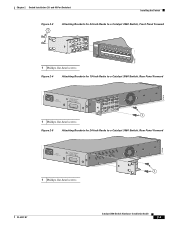
..., use depend on whether you are attaching the brackets for 19-Inch Racks to a Catalyst 3560 Switch, Front Panel Forward SYST RPS STAT DUPLX SPEED PoE MODE 1 1X 23 45 67 8 9 10 11 12 13 14 15 16 15X 2X 16X 1 Phillips flat-head screws 97917 Catalyst 3560 Switch Hardware... screws (see Figure 2-1.) Figure 2-1 Removing Screws from the Catalyst 3560 Switch 97916 40 41 42 43 44 45 46 47 48 47X Catalyst 3560 SERIES PoE-48 1 3 48X 2 4 Attaching Brackets to the Catalyst 3560 Switch The bracket orientation and the brackets that you use bracket part number 700-13248-01. ...
..., use depend on whether you are attaching the brackets for 19-Inch Racks to a Catalyst 3560 Switch, Front Panel Forward SYST RPS STAT DUPLX SPEED PoE MODE 1 1X 23 45 67 8 9 10 11 12 13 14 15 16 15X 2X 16X 1 Phillips flat-head screws 97917 Catalyst 3560 Switch Hardware... screws (see Figure 2-1.) Figure 2-1 Removing Screws from the Catalyst 3560 Switch 97916 40 41 42 43 44 45 46 47 48 47X Catalyst 3560 SERIES PoE-48 1 3 48X 2 4 Attaching Brackets to the Catalyst 3560 Switch The bracket orientation and the brackets that you use bracket part number 700-13248-01. ...
Hardware Installation Guide
Page 41
... the Switch Figure 2-3 1 Attaching Brackets for 24-Inch Racks to a Catalyst 3560 Switch, Front Panel Forward 1 Phillips flat-head screws SYST RPS STAT DUPLX SPEED PoE MODE 1 1X 23 45 67 8 9 10 11 12 13 14 15 16 15X 2X 16X 97918 Figure 2-4 Attaching Brackets for 19-Inch Racks to a Catalyst...
... the Switch Figure 2-3 1 Attaching Brackets for 24-Inch Racks to a Catalyst 3560 Switch, Front Panel Forward 1 Phillips flat-head screws SYST RPS STAT DUPLX SPEED PoE MODE 1 1X 23 45 67 8 9 10 11 12 13 14 15 16 15X 2X 16X 97918 Figure 2-4 Attaching Brackets for 19-Inch Racks to a Catalyst...
Hardware Installation Guide
Page 42
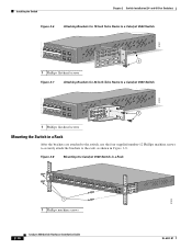
... 2-6 Attaching Brackets for 19-Inch Telco Racks to a Catalyst 3560 Switch 97921 40 41 42 43 44 45 46 47 48 47X Catalyst 3560 SERIES PoE-48 1 3 48X 2 4 1 1 Phillips flat-head screws Figure 2-7 Attaching Brackets for 24-Inch Telco Racks to a Catalyst 3560 Switch 97922 40 41 42 43 44... 45 46 47 48 47X Catalyst 3560 SERIES PoE-48 1 3 48X 2 1 4 1 Phillips flat-head screws Mounting the Switch in a Rack After the brackets are attached to the switch, use the four supplied ...
... 2-6 Attaching Brackets for 19-Inch Telco Racks to a Catalyst 3560 Switch 97921 40 41 42 43 44 45 46 47 48 47X Catalyst 3560 SERIES PoE-48 1 3 48X 2 4 1 1 Phillips flat-head screws Figure 2-7 Attaching Brackets for 24-Inch Telco Racks to a Catalyst 3560 Switch 97922 40 41 42 43 44... 45 46 47 48 47X Catalyst 3560 SERIES PoE-48 1 3 48X 2 1 4 1 Phillips flat-head screws Mounting the Switch in a Rack After the brackets are attached to the switch, use the four supplied ...
