
Hardware Installation Guide
Page 23
... more information about cabling requirements, see the software configuration guide. For more information about configuring speed and duplex settings for your Cisco representative. (See Figure 1-22.) OL-7075-09 Catalyst 2960 Switch Hardware Installation Guide 1-13 Dual-Purpose Port You can use... connections to establish fiber-optic connections. Each port is considered as an SFP module port. The dual front ends are field-replaceable, providing the uplink interfaces when you can order it from these SFP modules, see your SFP module documentation or the release...
... more information about cabling requirements, see the software configuration guide. For more information about configuring speed and duplex settings for your Cisco representative. (See Figure 1-22.) OL-7075-09 Catalyst 2960 Switch Hardware Installation Guide 1-13 Dual-Purpose Port You can use... connections to establish fiber-optic connections. Each port is considered as an SFP module port. The dual front ends are field-replaceable, providing the uplink interfaces when you can order it from these SFP modules, see your SFP module documentation or the release...
Hardware Installation Guide
Page 35
and 48-Port Switches) Preparing for installation in the absence of this product should be allowed to install, replace, or service this equipment. Statement 1006 Warning Class 1 laser product. A restricted access area can be connected through the use of a special tool, lock and key, ...
and 48-Port Switches) Preparing for installation in the absence of this product should be allowed to install, replace, or service this equipment. Statement 1006 Warning Class 1 laser product. A restricted access area can be connected through the use of a special tool, lock and key, ...

Hardware Installation Guide
Page 36
...free as possible from dust and foreign conductive material (such as fans and blowers. and 48-Port Switches) Warning When installing or replacing the unit, the ground connection must comply with cooling mechanisms, such as metal flakes from the switch to all Catalyst 2960 switches ...always be accessed only through the use both GLC-GE-100XX and GLC-FE-100XX SFP modules. These standards provide guidelines for Particulate Matter Cisco Ethernet switches are made first and disconnected last. Statement 1046 Warning Voltages that present a shock hazard may exist on page B-5, which ...
...free as possible from dust and foreign conductive material (such as fans and blowers. and 48-Port Switches) Warning When installing or replacing the unit, the ground connection must comply with cooling mechanisms, such as metal flakes from the switch to all Catalyst 2960 switches ...always be accessed only through the use both GLC-GE-100XX and GLC-FE-100XX SFP modules. These standards provide guidelines for Particulate Matter Cisco Ethernet switches are made first and disconnected last. Statement 1046 Warning Voltages that present a shock hazard may exist on page B-5, which ...
Hardware Installation Guide
Page 46
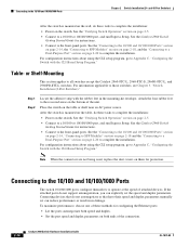
... the CLI setup program, go to a 10/100 or 10/100/1000 port, and run Express Setup. Note When the connectors are not being used, replace the dust covers on both ends of attached devices.
... the CLI setup program, go to a 10/100 or 10/100/1000 port, and run Express Setup. Note When the connectors are not being used, replace the dust covers on both ends of attached devices.

Hardware Installation Guide
Page 47
See Chapter 4, "Troubleshooting," for solutions to use a twisted four-pair, Category 5 or higher cable. These field-replaceable modules provide the uplink optical interfaces, laser send (TX) and laser receive (RX). Each SFP module must be of the same type as the SFP... any combination of the cable, and the cable must not exceed the stipulated cable length for loops. Step 1 When connecting to workstations, servers, routers, and Cisco IP Phones, connect a straight-through 3 to 30 seconds, and then the port LED turns green. The port LED is enabled by default. Installing and Removing...
See Chapter 4, "Troubleshooting," for solutions to use a twisted four-pair, Category 5 or higher cable. These field-replaceable modules provide the uplink optical interfaces, laser send (TX) and laser receive (RX). Each SFP module must be of the same type as the SFP... any combination of the cable, and the cable must not exceed the stipulated cable length for loops. Step 1 When connecting to workstations, servers, routers, and Cisco IP Phones, connect a straight-through 3 to 30 seconds, and then the port LED turns green. The port LED is enabled by default. Installing and Removing...
Hardware Installation Guide
Page 48
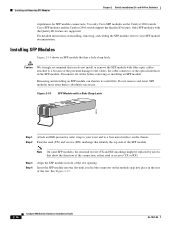
...On some SFP modules, the send and receive (TX and RX) markings might be replaced by arrows that has a bale-clasp latch. See Figure 2-15. 2-16 Catalyst 2960 Switch Hardware Installation ...Guide OL-7075-09 Use only Cisco SFP modules on the module snap into place in front of the connection, either send or receive... more often than is absolutely necessary. Disconnect all cables before removing or installing an SFP module. Cisco SFP modules and the Catalyst 2960 switch support the Quality ID feature. Insert the SFP module into...
...On some SFP modules, the send and receive (TX and RX) markings might be replaced by arrows that has a bale-clasp latch. See Figure 2-15. 2-16 Catalyst 2960 Switch Hardware Installation ...Guide OL-7075-09 Use only Cisco SFP modules on the module snap into place in front of the connection, either send or receive... more often than is absolutely necessary. Disconnect all cables before removing or installing an SFP module. Cisco SFP modules and the Catalyst 2960 switch support the Quality ID feature. Insert the SFP module into...

Hardware Installation Guide
Page 57
Statement 1044 Warning When installing or replacing the unit, the ground connection must be grounded. OL-7075-09 Catalyst 2960 Switch Hardware Installation Guide 3-3 Contact the appropriate electrical inspection authority or an ...
Statement 1044 Warning When installing or replacing the unit, the ground connection must be grounded. OL-7075-09 Catalyst 2960 Switch Hardware Installation Guide 3-3 Contact the appropriate electrical inspection authority or an ...

Hardware Installation Guide
Page 75
... Verify that both devices have power. • Verify that both sides have link. OL-7075-09 Catalyst 2960 Switch Hardware Installation Guide 4-3 Each Cisco module has an internal serial EEPROM that both ends of supported SFP modules. • Use the show link, but is fully functional. Chapter ... If the link light for 10 Mb/s unshielded twisted pair (UTP) connections. Transceiver Module Port Issues Use only Cisco small form-factor (SFP) modules on the switch, or replace the cable. A link LED does not guarantee that this module supports this platform. Verify that the cable is ...
... Verify that both devices have power. • Verify that both sides have link. OL-7075-09 Catalyst 2960 Switch Hardware Installation Guide 4-3 Each Cisco module has an internal serial EEPROM that both ends of supported SFP modules. • Use the show link, but is fully functional. Chapter ... If the link light for 10 Mb/s unshielded twisted pair (UTP) connections. Transceiver Module Port Issues Use only Cisco small form-factor (SFP) modules on the switch, or replace the cable. A link LED does not guarantee that this module supports this platform. Verify that the cable is ...

