
Hardware Installation Guide
Page 2
... BY THIS REFERENCE. Operation of actual IP addresses in a particular installation. You can radiate radio-frequency energy and, if not installed and used in accordance with Cisco's installation instructions, it is no longer complying with radio and television reception. NOTWITHSTANDING ANY OTHER WARRANTY HEREIN, ALL DOCUMENT FILES AND SOFTWARE OF THESE SUPPLIERS ARE PROVIDED "AS IS" WITH ALL FAULTS. Any examples, command display...
... BY THIS REFERENCE. Operation of actual IP addresses in a particular installation. You can radiate radio-frequency energy and, if not installed and used in accordance with Cisco's installation instructions, it is no longer complying with radio and television reception. NOTWITHSTANDING ANY OTHER WARRANTY HEREIN, ALL DOCUMENT FILES AND SOFTWARE OF THESE SUPPLIERS ARE PROVIDED "AS IS" WITH ALL FAULTS. Any examples, command display...

Hardware Installation Guide
Page 21
... command-line interface (CLI) to enable the automatic medium-dependent interface crossover (auto-MDIX) feature. You can use a twisted four-pair, Category 5 or higher cable for autonegotiation, it senses the speed and duplex settings of the connection. When you connect the switch to workstations, servers, routers, and Cisco IP Phones, be sure that the cable is autonegotiate.) When you can use the mdix auto interface configuration command in full-duplex or half-duplex mode. The default setting...
... command-line interface (CLI) to enable the automatic medium-dependent interface crossover (auto-MDIX) feature. You can use a twisted four-pair, Category 5 or higher cable for autonegotiation, it senses the speed and duplex settings of the connection. When you connect the switch to workstations, servers, routers, and Cisco IP Phones, be sure that the cable is autonegotiate.) When you can use the mdix auto interface configuration command in full-duplex or half-duplex mode. The default setting...

Hardware Installation Guide
Page 22
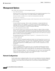
... Cisco prestandard PoE is connected. The device manager, Network Assistant, and the CLI provide PoE settings for devices that came with the switch. The powered device might reboot or reestablish link with your IP phone or access point. Front Panel Description Chapter 1 Product Overview PoE Ports (Only Catalyst 2960 PoE Switches) This section applies only to the powered device. Auto: When you can control whether or not a Catalyst 2960 PoE port automatically provides power when an IP phone or an access point is also supported for...
... Cisco prestandard PoE is connected. The device manager, Network Assistant, and the CLI provide PoE settings for devices that came with the switch. The powered device might reboot or reestablish link with your IP phone or access point. Front Panel Description Chapter 1 Product Overview PoE Ports (Only Catalyst 2960 PoE Switches) This section applies only to the powered device. Auto: When you can control whether or not a Catalyst 2960 PoE port automatically provides power when an IP phone or an access point is also supported for...

Hardware Installation Guide
Page 23
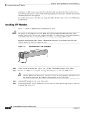
... the status of the SFP module port. By default, the switch dynamically selects the interface type that provides power (complies with LC connectors to connect to a copper SFP module. The port LED is not included with the switch, but you can order it from your Cisco representative. (See Figure 1-22.) OL-7075-09 Catalyst 2960 Switch Hardware Installation Guide 1-13 For more information about cabling requirements, see the software configuration guide. However, you insert an SFP module...
... the status of the SFP module port. By default, the switch dynamically selects the interface type that provides power (complies with LC connectors to connect to a copper SFP module. The port LED is not included with the switch, but you can order it from your Cisco representative. (See Figure 1-22.) OL-7075-09 Catalyst 2960 Switch Hardware Installation Guide 1-13 For more information about cabling requirements, see the software configuration guide. However, you insert an SFP module...
Hardware Installation Guide
Page 32
... or part of Cisco LAN switches, core switches, routers, access points, IP phones, and PIX firewalls. You can use Cisco Configuration Engine to create dedicated network segments that are interconnected through a web browser. The software configuration guide also provides examples of network configuration concepts. For more information, see the Getting Started with Cisco Network Assistant guide on Cisco.com for an explanation of network configurations that is enhanced to support desktop-switching features. See the Catalyst 2960 Switch Command Reference on Cisco.com...
... or part of Cisco LAN switches, core switches, routers, access points, IP phones, and PIX firewalls. You can use Cisco Configuration Engine to create dedicated network segments that are interconnected through a web browser. The software configuration guide also provides examples of network configuration concepts. For more information, see the Getting Started with Cisco Network Assistant guide on Cisco.com for an explanation of network configurations that is enhanced to support desktop-switching features. See the Catalyst 2960 Switch Command Reference on Cisco.com...
Hardware Installation Guide
Page 34
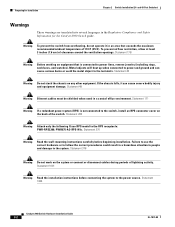
... Ethernet cables must be shielded when used in the Regulatory Compliance and Safety Information for Installation Chapter 2 Switch Installation (24- Statement 1001 Warning Read the installation instructions before beginning installation. Statement 1004 Catalyst 2960 Switch Hardware Installation Guide 2-2 OL-7075-09 Statement 265 Warning Attach only the following Cisco RPS model to power lines, remove jewelry (including rings, necklaces, and watches). Statement 370 Warning Read the wall-mounting instructions carefully before connecting...
... Ethernet cables must be shielded when used in the Regulatory Compliance and Safety Information for Installation Chapter 2 Switch Installation (24- Statement 1001 Warning Read the installation instructions before beginning installation. Statement 1004 Catalyst 2960 Switch Hardware Installation Guide 2-2 OL-7075-09 Statement 265 Warning Attach only the following Cisco RPS model to power lines, remove jewelry (including rings, necklaces, and watches). Statement 370 Warning Read the wall-mounting instructions carefully before connecting...

Hardware Installation Guide
Page 36
... restricted access location are made using uninsulated exposed metal contacts, conductors, or terminals. Statement 1072 Warning No user-serviceable parts inside the chassis, which lists the cable specifications for 1000BASE-X and 100BASE-X SFP modules for the Catalyst 2960 switch. You must always be sure to observe these fans and blowers can draw dust and other means of the hazard. and 48-Port Switches) Warning When installing or replacing...
... restricted access location are made using uninsulated exposed metal contacts, conductors, or terminals. Statement 1072 Warning No user-serviceable parts inside the chassis, which lists the cable specifications for 1000BASE-X and 100BASE-X SFP modules for the Catalyst 2960 switch. You must always be sure to observe these fans and blowers can draw dust and other means of the hazard. and 48-Port Switches) Warning When installing or replacing...

Hardware Installation Guide
Page 38
Statement 370 As the switch powers on page 2-6. The System LED blinks green, and the other LEDs turn green. If a switch fails POST, the System LED turns amber. or Shelf-Mounting, page 2-14 Rack-Mounting This section applies to all switches except the Catalyst 8-port switches. The RPS LED remains green for some time and then reflects the switch operating status. Installing the Switch This section applies to all switches except the Catalyst 8-port switches. For information applicable to ensure that the...
Statement 370 As the switch powers on page 2-6. The System LED blinks green, and the other LEDs turn green. If a switch fails POST, the System LED turns amber. or Shelf-Mounting, page 2-14 Rack-Mounting This section applies to all switches except the Catalyst 8-port switches. The RPS LED remains green for some time and then reflects the switch operating status. Installing the Switch This section applies to all switches except the Catalyst 8-port switches. For information applicable to ensure that the...
Hardware Installation Guide
Page 45
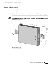
... switches on a Wall For the best support of the switch. Chapter 2 Switch Installation (24- Statement 266 Warning If a redundant power system (RPS) is attached securely to wall studs or to the switch, install an RPS connector cover on a Wall 11X 12X 11X 1X 12X 11X 1X 12X 1X 1X 11X 1X 12X MODE STASCPKEDEUDPSLTXAMTASRTPRSSYST 1 1 1 User-supplied screws 204621 OL-7075-09 Catalyst 2960 Switch Hardware Installation Guide...
... switches on a Wall For the best support of the switch. Chapter 2 Switch Installation (24- Statement 266 Warning If a redundant power system (RPS) is attached securely to wall studs or to the switch, install an RPS connector cover on a Wall 11X 12X 11X 1X 12X 11X 1X 12X 1X 1X 11X 1X 12X MODE STASCPKEDEUDPSLTXAMTASRTPRSSYST 1 1 1 User-supplied screws 204621 OL-7075-09 Catalyst 2960 Switch Hardware Installation Guide...

Hardware Installation Guide
Page 47
... the switch and the connected device have established link. Refer to the Catalyst 2960 switch release notes for solutions to 30 seconds, and then the port LED turns green. The port LED is enabled by default. You can take up to cabling problems. Reconfigure and reboot the connected device if necessary. See the "SFP Module Cable Specifications" section on page B-4 for this feature, see the switch software configuration guide or the switch command reference. Step 1 When connecting to workstations, servers, routers, and Cisco IP Phones, connect a straight...
... the switch and the connected device have established link. Refer to the Catalyst 2960 switch release notes for solutions to 30 seconds, and then the port LED turns green. The port LED is enabled by default. You can take up to cabling problems. Reconfigure and reboot the connected device if necessary. See the "SFP Module Cable Specifications" section on page B-4 for this feature, see the switch software configuration guide or the switch command reference. Step 1 When connecting to workstations, servers, routers, and Cisco IP Phones, connect a straight...
Hardware Installation Guide
Page 48
... on installing, removing, and cabling the SFP module, refer to your wrist and to the cables, the cable connector, or the optical interfaces in the SFP module. and 48-Port Switches) stipulations for SFP module connections. For detailed instructions on the module snap into the slot until you do not install or remove the SFP module with the Quality ID feature are supported. Cisco SFP modules and the Catalyst 2960 switch support the Quality ID feature. Installing and Removing SFP Modules Chapter 2 Switch Installation (24...
... on installing, removing, and cabling the SFP module, refer to your wrist and to the cables, the cable connector, or the optical interfaces in the SFP module. and 48-Port Switches) stipulations for SFP module connections. For detailed instructions on the module snap into the slot until you do not install or remove the SFP module with the Quality ID feature are supported. Cisco SFP modules and the Catalyst 2960 switch support the Quality ID feature. Installing and Removing SFP Modules Chapter 2 Switch Installation (24...

Hardware Installation Guide
Page 57
...ranges listed in a multirack assembly, the temperature around it might be greater than 10,000 feet (3,049 meters). • The bottom of the switch. If the switch is installed in the absence of the equipment must comply with integral circuit protection: 10/100/1000 Ethernet. OL-7075-09 Catalyst 2960 Switch Hardware Installation Guide 3-3 Warning For connections... Specifications." • Airflow around the switch and through an approved network termination unit with local and national electrical codes. Do not open. Statement 1046 Warning No user-serviceable parts inside...
...ranges listed in a multirack assembly, the temperature around it might be greater than 10,000 feet (3,049 meters). • The bottom of the switch. If the switch is installed in the absence of the equipment must comply with integral circuit protection: 10/100/1000 Ethernet. OL-7075-09 Catalyst 2960 Switch Hardware Installation Guide 3-3 Warning For connections... Specifications." • Airflow around the switch and through an approved network termination unit with local and national electrical codes. Do not open. Statement 1046 Warning No user-serviceable parts inside...
Hardware Installation Guide
Page 73
... Switch Serial Number, page 4-6 Diagnosing Problems The LEDs on page 1-14. This chapter describes these topics for details. They show failures in the power-on self-test (POST), port-connectivity problems, and overall switch performance. You can also get statistics from the CLI or from a Simple Network Management Protocol (SNMP) workstation. Troubleshooting 4 C H A P T E R The LEDs on the front panel provide troubleshooting information about the switch. See the software configuration guide and the switch command reference on Cisco.com or the documentation...
... Switch Serial Number, page 4-6 Diagnosing Problems The LEDs on page 1-14. This chapter describes these topics for details. They show failures in the power-on self-test (POST), port-connectivity problems, and overall switch performance. You can also get statistics from the CLI or from a Simple Network Management Protocol (SNMP) workstation. Troubleshooting 4 C H A P T E R The LEDs on the front panel provide troubleshooting information about the switch. See the software configuration guide and the switch command reference on Cisco.com or the documentation...

Hardware Installation Guide
Page 75
... that this module supports this platform. See the "Features" section on the switch, or replace the cable. See Appendix B, "Connector and Cable Specifications." Re-enable the port if necessary. • Make sure that all fiber-optic connections. Chapter 4 Troubleshooting Diagnosing Problems Ethernet and Fiber Cables Make sure that you have properly cleaned and securely connected all you have the correct cable type for the connection: • For Ethernet, use the same type of encoding...
... that this module supports this platform. See the "Features" section on the switch, or replace the cable. See Appendix B, "Connector and Cable Specifications." Re-enable the port if necessary. • Make sure that all fiber-optic connections. Chapter 4 Troubleshooting Diagnosing Problems Ethernet and Fiber Cables Make sure that you have properly cleaned and securely connected all you have the correct cable type for the connection: • For Ethernet, use the same type of encoding...
Hardware Installation Guide
Page 76
... or server. This occurs when the traffic that the switch sends is used repeatedly by its Content-Addressable Memory (CAM) table. A unidirectional link can happen when you troubleshoot switch performance problems: • Speed, Duplex, and Autonegotiation, page 4-4 • Autonegotiation and NIC Cards, page 4-5 • Cabling Distance, page 4-5 Speed, Duplex, and Autonegotiation If the port statistics show interfaces privileged EXEC command to -find the source of port connectivity failure is manually...
... or server. This occurs when the traffic that the switch sends is used repeatedly by its Content-Addressable Memory (CAM) table. A unidirectional link can happen when you troubleshoot switch performance problems: • Speed, Duplex, and Autonegotiation, page 4-4 • Autonegotiation and NIC Cards, page 4-5 • Cabling Distance, page 4-5 Speed, Duplex, and Autonegotiation If the port statistics show interfaces privileged EXEC command to -find the source of port connectivity failure is manually...
Hardware Installation Guide
Page 77
... mode button turn green. The LEDs stop blinking after about 2 seconds. By default, the switch ports and interfaces are set to completely reconfigure the switch. Follow these guidelines when you want to autonegotiate, yet sometimes autonegotiation issues occur. If this does not solve the problem, the firmware or software on the switch. Upgrade the NIC card driver to configure the switch. 2. The speed parameter can omit this procedure unless you set or change the settings...
... mode button turn green. The LEDs stop blinking after about 2 seconds. By default, the switch ports and interfaces are set to completely reconfigure the switch. Follow these guidelines when you want to autonegotiate, yet sometimes autonegotiation issues occur. If this does not solve the problem, the firmware or software on the switch. Upgrade the NIC card driver to configure the switch. 2. The speed parameter can omit this procedure unless you set or change the settings...
Hardware Installation Guide
Page 95
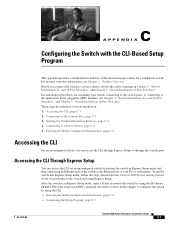
... switch to the Ethernet port of your switch, connecting to the switch ports, or connecting to the switch by placing the switch in the Catalyst 2960 Switch Getting Started Guide for mounting your PC or workstation. Starting the Terminal Emulation Software, page C-3 4. After the switch is in Express Setup mode, open a Telnet session to the small form-factor pluggable (SFP) modules, see Chapter 1, "Product Overview." and 48-Port Switches)," and Chapter 3, "Switch Installation (8-Port Switches)." Entering the Initial Configuration Information, page C-4 Accessing the CLI...
... switch to the Ethernet port of your switch, connecting to the switch ports, or connecting to the switch by placing the switch in the Catalyst 2960 Switch Getting Started Guide for mounting your PC or workstation. Starting the Terminal Emulation Software, page C-3 4. After the switch is in Express Setup mode, open a Telnet session to the small form-factor pluggable (SFP) modules, see Chapter 1, "Product Overview." and 48-Port Switches)," and Chapter 3, "Switch Installation (8-Port Switches)." Entering the Initial Configuration Information, page C-4 Accessing the CLI...

Hardware Installation Guide
Page 98
.... When the POST completes successfully, the System LED remains green. The other LEDs remain solid green. Catalyst 2960 Switch Hardware Installation Guide C-4 OL-7075-09 The System LED blinks green, and the other LEDs turn green. If a switch fails POST, the System LED turns amber. POST failures are connecting the switch to a Cisco redundant power system (RPS), refer to the documentation that the switch functions properly. You need to complete the setup program, which runs automatically after the...
.... When the POST completes successfully, the System LED remains green. The other LEDs remain solid green. Catalyst 2960 Switch Hardware Installation Guide C-4 OL-7075-09 The System LED blinks green, and the other LEDs turn green. If a switch fails POST, the System LED turns amber. POST failures are connecting the switch to a Cisco redundant power system (RPS), refer to the documentation that the switch functions properly. You need to complete the setup program, which runs automatically after the...
Hardware Installation Guide
Page 104
... B-3 SFP module ports B-3 console port connecting to C-3 described 1-21 specifications B-4 to B-8 crossover cable B-7 crossover cable, connecting to 1000BASE-T SFP module ports 2-19 crossover cable pinout, four twisted-pair, 1000BASE-T ports B-7 D DC power RPS 1-3 IN-2 Catalyst 2960 Switch Hardware Installation Guide descriptions of switch models 1-1 desk-mounting 2-14, 3-6 device manager described 1-22 to 1-17 SFP module ports 1-13 OL-7075-09 and 48-port switches 2-2 8-port switches 3-2 Ethernet ports warning 3-3 examples, network configuration 1-1 Express Setup, accessing CLI by using...
... B-3 SFP module ports B-3 console port connecting to C-3 described 1-21 specifications B-4 to B-8 crossover cable B-7 crossover cable, connecting to 1000BASE-T SFP module ports 2-19 crossover cable pinout, four twisted-pair, 1000BASE-T ports B-7 D DC power RPS 1-3 IN-2 Catalyst 2960 Switch Hardware Installation Guide descriptions of switch models 1-1 desk-mounting 2-14, 3-6 device manager described 1-22 to 1-17 SFP module ports 1-13 OL-7075-09 and 48-port switches 2-2 8-port switches 3-2 Ethernet ports warning 3-3 examples, network configuration 1-1 Express Setup, accessing CLI by using...

Hardware Installation Guide
Page 107
... twisted-pair 10/100 ports B-6 SunNet Manager 1-22 switch descriptions 1-1 switch powering on 2-5, 3-5 system LED 1-15 T technical specifications A-1 telco racks 2-7, 3-15 Telnet, and accessing the CLI 1-22 temperature, operating A-1 terminal emulation software C-3 trained and qualified personnel warning 2-3 troubleshooting 4-1 to 4-6 OL-7075-09 Index bad or damaged cable 4-2 connection problems 4-2 diagnosing problems 4-1 Ethernet and fiber-optic cables 4-3 link status 4-3 ping end device 4-4 port and interface settings 4-4 POST 4-1 spanning tree loops 4-4 speed, duplex, and autonegotiation...
... twisted-pair 10/100 ports B-6 SunNet Manager 1-22 switch descriptions 1-1 switch powering on 2-5, 3-5 system LED 1-15 T technical specifications A-1 telco racks 2-7, 3-15 Telnet, and accessing the CLI 1-22 temperature, operating A-1 terminal emulation software C-3 trained and qualified personnel warning 2-3 troubleshooting 4-1 to 4-6 OL-7075-09 Index bad or damaged cable 4-2 connection problems 4-2 diagnosing problems 4-1 Ethernet and fiber-optic cables 4-3 link status 4-3 ping end device 4-4 port and interface settings 4-4 POST 4-1 spanning tree loops 4-4 speed, duplex, and autonegotiation...


