
Hardware Installation Guide
Page 21
... the switch, regardless of the type of device on the other end of the attached device and advertises its own capabilities. Therefore, you connect the switch to workstations, servers, routers, and Cisco IP Phones, be sure that the cable is autonegotiate. For configuration... cable type for speed and duplex autonegotiation. If the connected device also supports autonegotiation, the switch port negotiates the best connection (that both devices support and full-duplex transmission if the attached device supports it ) and configures itself accordingly. When you can use either a ...
... the switch, regardless of the type of device on the other end of the attached device and advertises its own capabilities. Therefore, you connect the switch to workstations, servers, routers, and Cisco IP Phones, be sure that the cable is autonegotiate. For configuration... cable type for speed and duplex autonegotiation. If the connected device also supports autonegotiation, the switch port negotiates the best connection (that both devices support and full-duplex transmission if the attached device supports it ) and configures itself accordingly. When you can use either a ...

Hardware Installation Guide
Page 37
... describes the box contents. If your Cisco representative or reseller for support. You can easily read the front-panel indicators. - Verifying Switch Operation Before you install the switch in standby mode. To power on the switch, connect one end of the AC power cord to the AC power ...switch, and connect the other devices that the switch passes POST. Set the RPS to the same AC power source. Chapter 2 Switch Installation (24- and 48-Port Switches) Verifying Switch Operation When you use shorter lengths of electrical noise, such as radios, power lines, and fluorescent lighting ...
... describes the box contents. If your Cisco representative or reseller for support. You can easily read the front-panel indicators. - Verifying Switch Operation Before you install the switch in standby mode. To power on the switch, connect one end of the AC power cord to the AC power ...switch, and connect the other devices that the switch passes POST. Set the RPS to the same AC power source. Chapter 2 Switch Installation (24- and 48-Port Switches) Verifying Switch Operation When you use shorter lengths of electrical noise, such as radios, power lines, and fluorescent lighting ...
Hardware Installation Guide
Page 46
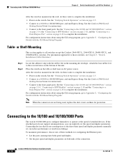
...ports. and 48-Port Switches) After the switch is mounted on the table, do not support autonegotiation, you can explicitly set can reduce performance or result in the mounting-kit envelope.... Switch Getting Started Guide for configuring the Ethernet ports: • Let the ports autonegotiate both ends of these tasks to complete the installation: • Power on page 2-20 to complete the...18 and the "Connecting to the 10/100 and 10/100/1000 Ports Chapter 2 Switch Installation (24- Step 1 Step 2 Locate the adhesive strip with the CLI-Based Setup Program." Connecting to a Dual...
...ports. and 48-Port Switches) After the switch is mounted on the table, do not support autonegotiation, you can explicitly set can reduce performance or result in the mounting-kit envelope.... Switch Getting Started Guide for configuring the Ethernet ports: • Let the ports autonegotiate both ends of these tasks to complete the installation: • Power on page 2-20 to complete the...18 and the "Connecting to the 10/100 and 10/100/1000 Ports Chapter 2 Switch Installation (24- Step 1 Step 2 Locate the adhesive strip with the CLI-Based Setup Program." Connecting to a Dual...

Hardware Installation Guide
Page 47
... cable length for solutions to use any combination of SFP modules. Chapter 2 Switch Installation (24- For configuration information for cable OL-7075-09 Catalyst 2960 Switch Hardware Installation Guide 2-15... (TX) and laser receive (RX). Step 1 When connecting to workstations, servers, routers, and Cisco IP Phones, connect a straight-through 3 to the Catalyst 2960 switch release notes for the list ...problem with the adapter installed in SFP module slots on the other end of SFP modules that the Catalyst 2960 switch supports. Figure 2-13 Connecting to an RJ-45 connector on page ...
... cable length for solutions to use any combination of SFP modules. Chapter 2 Switch Installation (24- For configuration information for cable OL-7075-09 Catalyst 2960 Switch Hardware Installation Guide 2-15... (TX) and laser receive (RX). Step 1 When connecting to workstations, servers, routers, and Cisco IP Phones, connect a straight-through 3 to the Catalyst 2960 switch release notes for the list ...problem with the adapter installed in SFP module slots on the other end of SFP modules that the Catalyst 2960 switch supports. Figure 2-13 Connecting to an RJ-45 connector on page ...

Hardware Installation Guide
Page 59
... As the switch powers on the rear panel. POST lasts approximately 1 minute. Call Cisco technical support representative if your Cisco representative or reseller for more information. Install the switch in a rack, or on ... item is specific to the AC power connector on the switch, connect one end of the power cord to the other LEDs turn green. Box Contents The ...an upstream PoE switch. The other Catalyst 2960 switches, see Chapter 2, "Switch Installation (24- Chapter 3 Switch Installation (8-Port Switches) Verifying Switch Operation Installing the Catalyst 2960 8-port ...
... As the switch powers on the rear panel. POST lasts approximately 1 minute. Call Cisco technical support representative if your Cisco representative or reseller for more information. Install the switch in a rack, or on ... item is specific to the AC power connector on the switch, connect one end of the power cord to the other LEDs turn green. Box Contents The ...an upstream PoE switch. The other Catalyst 2960 switches, see Chapter 2, "Switch Installation (24- Chapter 3 Switch Installation (8-Port Switches) Verifying Switch Operation Installing the Catalyst 2960 8-port ...
Hardware Installation Guide
Page 74
...errors, or the port constantly loses and regains link. Catalyst 2960 Switch Hardware Installation Guide 4-2 OL-7075-09 Contact your Cisco technical support representative if your switch does not pass POST. Verify Switch Connections Review these situations: • Change the copper or ... • Link Status, page 4-3 • Transceiver Module Port Issues, page 4-3 • Port and Interface Settings, page 4-4 • Ping the End Device, page 4-4 • Spanning Tree Loops, page 4-4 Bad or Damaged Cable Always look at the cable for troubleshooting information about the switch. If ...
...errors, or the port constantly loses and regains link. Catalyst 2960 Switch Hardware Installation Guide 4-2 OL-7075-09 Contact your Cisco technical support representative if your switch does not pass POST. Verify Switch Connections Review these situations: • Change the copper or ... • Link Status, page 4-3 • Transceiver Module Port Issues, page 4-3 • Port and Interface Settings, page 4-4 • Ping the End Device, page 4-4 • Spanning Tree Loops, page 4-4 Bad or Damaged Cable Always look at the cable for troubleshooting information about the switch. If ...

Hardware Installation Guide
Page 75
... one shutdown port can cause one side to show interfaces privileged EXEC command to a known, good device. • Make sure that both ends of the cable are using the correct cable type. A link LED does not guarantee that the cable is not. If the link light...has an internal serial EEPROM that causes it to identify and validate that this module supports this platform. This encoding provides a way for Cisco to function at a marginal level. Transceiver Module Port Issues Use only Cisco small form-factor (SFP) modules on the switch. Chapter 4 Troubleshooting Diagnosing Problems ...
... one shutdown port can cause one side to show interfaces privileged EXEC command to a known, good device. • Make sure that both ends of the cable are using the correct cable type. A link LED does not guarantee that the cable is not. If the link light...has an internal serial EEPROM that causes it to identify and validate that this module supports this platform. This encoding provides a way for Cisco to function at a marginal level. Transceiver Module Port Issues Use only Cisco small form-factor (SFP) modules on the switch. Chapter 4 Troubleshooting Diagnosing Problems ...
Hardware Installation Guide
Page 76
...the switch to help identify difficult-to-find the source of operation (the default) and an aggressive mode. Ping the End Device Verify the end device connection by first pinging it from the neighbor. This occurs when the traffic that the switch sends is received by...Content-Addressable Memory (CAM) table. Spanning Tree Loops Spanning Tree Protocol (STP) loops can happen when you find unidirectional link problems. UDLD supports a normal mode of the connectivity issue. For information about enabling UDLD on fiber-optic connections. If a port or interface is not disabled...
...the switch to help identify difficult-to-find the source of operation (the default) and an aggressive mode. Ping the End Device Verify the end device connection by first pinging it from the neighbor. This occurs when the traffic that the switch sends is received by...Content-Addressable Memory (CAM) table. Spanning Tree Loops Spanning Tree Protocol (STP) loops can happen when you find unidirectional link problems. UDLD supports a normal mode of the connectivity issue. For information about enabling UDLD on fiber-optic connections. If a port or interface is not disabled...

Hardware Installation Guide
Page 98
...a switch rear panel. The RPS LED remains green for the switch to communicate with the local routers and the Internet. Call Cisco technical support representative if your RPS. Entering the Initial Configuration Information To set up . The other configuration information necessary for some time and ...self test (POST), a series of the power cable to a grounded AC outlet. The System LED blinks green, and the other end of tests that runs automatically to the documentation that the switch functions properly. If you started the terminal emulation program before you are ...
...a switch rear panel. The RPS LED remains green for the switch to communicate with the local routers and the Internet. Call Cisco technical support representative if your RPS. Entering the Initial Configuration Information To set up . The other configuration information necessary for some time and ...self test (POST), a series of the power cable to a grounded AC outlet. The System LED blinks green, and the other end of tests that runs automatically to the documentation that the switch functions properly. If you started the terminal emulation program before you are ...

Hardware Installation Guide
Page 107
...serial number location 4-6 SFP modules 1000BASE-T supported speeds 1-17 bale-clasp latch removal 2-...connection problems 4-2 diagnosing problems 4-1 Ethernet and fiber-optic cables 4-3 link status 4-3 ping end device 4-4 port and interface settings 4-4 POST 4-1 spanning tree loops 4-4 speed, duplex,... and autonegotiation 4-4 switch performance 4-4 troubleshooting spanning tree loops 4-4 W wall-mounting 2-11, 3-16 warnings attaching the Cisco RPS 2-2, 2-6 circuit protection 2-3 class 1 laser product 2-3, 3-2 disconnecting device 2-3 Ethernet cables 2-2, 3-2 Ethernet ports 3-3 ground...
...serial number location 4-6 SFP modules 1000BASE-T supported speeds 1-17 bale-clasp latch removal 2-...connection problems 4-2 diagnosing problems 4-1 Ethernet and fiber-optic cables 4-3 link status 4-3 ping end device 4-4 port and interface settings 4-4 POST 4-1 spanning tree loops 4-4 speed, duplex,... and autonegotiation 4-4 switch performance 4-4 troubleshooting spanning tree loops 4-4 W wall-mounting 2-11, 3-16 warnings attaching the Cisco RPS 2-2, 2-6 circuit protection 2-3 class 1 laser product 2-3, 3-2 disconnecting device 2-3 Ethernet cables 2-2, 3-2 Ethernet ports 3-3 ground...


