Hardware Installation Guide
Page 2
... service marks of Cisco Systems, Inc.; The following information is for a Class B digital device in accordance with the specifications in this manual generates and may cause interference with Cisco's installation instructions, it is likely to provide reasonable protection against such interference in the United States and certain other trademarks mentioned in part 15 of Class A devices: This equipment has been tested...
... service marks of Cisco Systems, Inc.; The following information is for a Class B digital device in accordance with the specifications in this manual generates and may cause interference with Cisco's installation instructions, it is likely to provide reasonable protection against such interference in the United States and certain other trademarks mentioned in part 15 of Class A devices: This equipment has been tested...
Hardware Installation Guide
Page 21
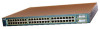
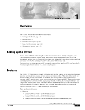
...-Panel Description, page 1-21 • Management Options, page 1-24 Setting up your switch by using the command-line interface (CLI), see Appendix D, "Configuring the Switch with gigabit interface converter (GBIC) module slots to connect workstations and other network devices, such as backbone switches, aggregating 10BASE-T, 100BASE-TX, Gigabit Ethernet, and Long-Reach Ethernet (LRE) traffic from other switches. and DC-powered switches, and troubleshooting help. You can use switches with the CLI-Based Setup Program." Catalyst 2950-12 switch-12 10/100 Ethernet ports...
...-Panel Description, page 1-21 • Management Options, page 1-24 Setting up your switch by using the command-line interface (CLI), see Appendix D, "Configuring the Switch with gigabit interface converter (GBIC) module slots to connect workstations and other network devices, such as backbone switches, aggregating 10BASE-T, 100BASE-TX, Gigabit Ethernet, and Long-Reach Ethernet (LRE) traffic from other switches. and DC-powered switches, and troubleshooting help. You can use switches with the CLI-Based Setup Program." Catalyst 2950-12 switch-12 10/100 Ethernet ports...

Hardware Installation Guide
Page 22
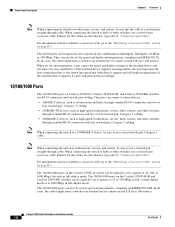
... the Catalyst 2950T-48-SI and 2950 LRE switches, autonegotiates the speed and duplex setting when operating at 1000 Mbps, it supports only full-duplex mode. - For 1000BASE-SX ports, supports only 1000-Mbps and full-duplex settings - Catalyst 2950SX-24 switch-24 10/100 Ethernet ports and 2 1000BASE-SX ports - Checks for these GBIC modules: 1000BASE-SX GBIC 1000BASE-LX/LH GBIC 1000BASE-ZX GBIC 1000BASE-T GBIC (model WS...
... the Catalyst 2950T-48-SI and 2950 LRE switches, autonegotiates the speed and duplex setting when operating at 1000 Mbps, it supports only full-duplex mode. - For 1000BASE-SX ports, supports only 1000-Mbps and full-duplex settings - Catalyst 2950SX-24 switch-24 10/100 Ethernet ports and 2 1000BASE-SX ports - Checks for these GBIC modules: 1000BASE-SX GBIC 1000BASE-LX/LH GBIC 1000BASE-ZX GBIC 1000BASE-T GBIC (model WS...
Hardware Installation Guide
Page 28
... Catalyst 2950T-24, Catalyst 2950T-48-SI, and Catalyst 2950 LRE switches use RJ-45 connectors and twisted-pair cabling. The 10/100/1000 ports can also be explicitly set for the cables are described in full-duplex mode. When connecting the switch to operate at 1000 Mbps in Appendix B, "Connectors and Cables." Pinouts for the cables are described in full-duplex mode. If the attached device supports autonegotiation, the port...
... Catalyst 2950T-24, Catalyst 2950T-48-SI, and Catalyst 2950 LRE switches use RJ-45 connectors and twisted-pair cabling. The 10/100/1000 ports can also be explicitly set for the cables are described in full-duplex mode. When connecting the switch to operate at 1000 Mbps in Appendix B, "Connectors and Cables." Pinouts for the cables are described in full-duplex mode. If the attached device supports autonegotiation, the port...
Hardware Installation Guide
Page 29
... logical ports, the switch chooses the fiber-optic connections over distances of up to the switch and private branch exchange (PBX) switch or public switched telephone network (PSTN). Use the Cisco part numbers in Figure 1-8) uses one time. The link between the LRE switch port and each logical port, you need. The default mode for the Cisco LRE 48 POTS Splitter. The PBX routes voice traffic to 4921 feet (1500 meters). In full-duplex mode, the cable...
... logical ports, the switch chooses the fiber-optic connections over distances of up to the switch and private branch exchange (PBX) switch or public switched telephone network (PSTN). Use the Cisco part numbers in Figure 1-8) uses one time. The link between the LRE switch port and each logical port, you need. The default mode for the Cisco LRE 48 POTS Splitter. The PBX routes voice traffic to 4921 feet (1500 meters). In full-duplex mode, the cable...

Hardware Installation Guide
Page 30
... 393,719 feet (120 kilometers). • GigaStack GBIC module for creating a 1-Gbps stack configuration of up to nine half-duplex links (in an error-disabled state. If the serial number, the vendor name or ID, security code, or CRC is required to connect directly to nine supported switches. For more information about homologated POTS splitters, contact your GBIC module documentation. 1-10 Catalyst 2950 Switch Hardware Installation Guide OL-6156-01
... 393,719 feet (120 kilometers). • GigaStack GBIC module for creating a 1-Gbps stack configuration of up to nine half-duplex links (in an error-disabled state. If the serial number, the vendor name or ID, security code, or CRC is required to connect directly to nine supported switches. For more information about homologated POTS splitters, contact your GBIC module documentation. 1-10 Catalyst 2950 Switch Hardware Installation Guide OL-6156-01

Hardware Installation Guide
Page 31
... example, you connect to 328 feet (100 meters). • Table 1-2 lists the cable specifications for the list of a copper 10/100/1000 port and a fiber-optic SFP module slot. Chapter 1 Overview Front-Panel Description SFP Module Slots On the Catalyst 2950 LRE switch, the SFP module slots support the SFP modules listed in default operation, the SFP module port has priority over the 10/100/1000 port. Note By using the media-type {sfp | rj45 | auto-select} interface configuration command at the CLI, you can connect...
... example, you connect to 328 feet (100 meters). • Table 1-2 lists the cable specifications for the list of a copper 10/100/1000 port and a fiber-optic SFP module slot. Chapter 1 Overview Front-Panel Description SFP Module Slots On the Catalyst 2950 LRE switch, the SFP module slots support the SFP modules listed in default operation, the SFP module port has priority over the 10/100/1000 port. Note By using the media-type {sfp | rj45 | auto-select} interface configuration command at the CLI, you can connect...

Hardware Installation Guide
Page 36
... power-on self-test (POST), see the "Connecting to a Power Source" section on the RPS, and the LED should turn green. Table 1-3 lists the LED colors and meanings. Flashing green RPS is connected but is providing power to another device (redundancy has been allocated to a neighboring device). Port Mode and Port Status LEDs To select or change the port mode, press the Mode button (see Table 1-5) determine the type of information displayed. 1-16 Catalyst 2950 Switch Hardware Installation Guide OL-6156-01 Table 1-4 lists the LED...
... power-on self-test (POST), see the "Connecting to a Power Source" section on the RPS, and the LED should turn green. Table 1-3 lists the LED colors and meanings. Flashing green RPS is connected but is providing power to another device (redundancy has been allocated to a neighboring device). Port Mode and Port Status LEDs To select or change the port mode, press the Mode button (see Table 1-5) determine the type of information displayed. 1-16 Catalyst 2950 Switch Hardware Installation Guide OL-6156-01 Table 1-4 lists the LED...
Hardware Installation Guide
Page 44
... bridge MIB, and four Remote Monitoring (RMON) groups. You can access the device manager from anywhere in your network through the console port and the supplied RJ-45-to-DB-9 adapter cable. To launch the Device Manager, enter the switch IP address in the switch memory, to manage and monitor switch clusters or standalone devices. The device manager page appears. For setup instructions that use the CLI, go to Appendix D, "Configuring the Switch with your SNMP application. 1-24 Catalyst 2950 Switch Hardware Installation Guide...
... bridge MIB, and four Remote Monitoring (RMON) groups. You can access the device manager from anywhere in your network through the console port and the supplied RJ-45-to-DB-9 adapter cable. To launch the Device Manager, enter the switch IP address in the switch memory, to manage and monitor switch clusters or standalone devices. The device manager page appears. For setup instructions that use the CLI, go to Appendix D, "Configuring the Switch with your SNMP application. 1-24 Catalyst 2950 Switch Hardware Installation Guide...

Hardware Installation Guide
Page 52
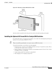
... switch and verify that adapter from Cisco. If POST fails, see Chapter 3, "Troubleshooting," to the switch - Note POST failures are green. Determine where you want to connect a terminal to the switch console port, you should power on , it automatically begins POST, a series of the mounting brackets - Verifying Switch Operation Before installing the switch in the getting started guide for attaching the brackets to a rack Note The DC-switch kit ships only with the Catalyst...
... switch and verify that adapter from Cisco. If POST fails, see Chapter 3, "Troubleshooting," to the switch - Note POST failures are green. Determine where you want to connect a terminal to the switch console port, you should power on , it automatically begins POST, a series of the mounting brackets - Verifying Switch Operation Before installing the switch in the getting started guide for attaching the brackets to a rack Note The DC-switch kit ships only with the Catalyst...
Hardware Installation Guide
Page 65
... lug and hardware (Cisco part number NEBS-LUG-3550=). Chapter 2 Installation Figure 2-20 Mounting a Catalyst 2950 Switch to a Wall Vertical wall stud Installing the Switch Vertical wall stud Catalyst 2950 SERIES LRE 2A 2B 13 14 15 16 17 18 19 20 21 22 23 24 9 10 11 12 1.01A/000.-51A275/02-R06A00-TI2HN4ZM0GVO~DE SPEESDTAT RPS SYST CONSOLE 1 2 3 4 5 6 7 8 86317 User-supplied screws Face...
... lug and hardware (Cisco part number NEBS-LUG-3550=). Chapter 2 Installation Figure 2-20 Mounting a Catalyst 2950 Switch to a Wall Vertical wall stud Installing the Switch Vertical wall stud Catalyst 2950 SERIES LRE 2A 2B 13 14 15 16 17 18 19 20 21 22 23 24 9 10 11 12 1.01A/000.-51A275/02-R06A00-TI2HN4ZM0GVO~DE SPEESDTAT RPS SYST CONSOLE 1 2 3 4 5 6 7 8 86317 User-supplied screws Face...
Hardware Installation Guide
Page 73
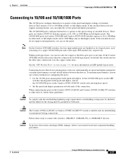
... default, the switch chooses the fiber-optic connections over the copper connections. To maximize performance, choose one time. Note On the Catalyst 2950 LRE switches, the four input uplink ports are bundled as two logical ports, each logical port, you can reduce performance or result in link failures between the devices. If the Catalyst 2950 LRE switch senses more information on Catalyst 2950 LRE and Catalyst 2950T-48-SI switches...
... default, the switch chooses the fiber-optic connections over the copper connections. To maximize performance, choose one time. Note On the Catalyst 2950 LRE switches, the four input uplink ports are bundled as two logical ports, each logical port, you can reduce performance or result in link failures between the devices. If the Catalyst 2950 LRE switch senses more information on Catalyst 2950 LRE and Catalyst 2950T-48-SI switches...
Hardware Installation Guide
Page 76
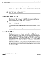
... switch, you do not need to use a Cisco LRE 48 POTS Splitter. Connecting to cabling problems. Reconfigure and restart the target device if necessary. See Chapter 3, "Troubleshooting," for solutions to an LRE Port Chapter 2 Installation Step 5 Step 6 The LED turns amber while STP discovers the network topology and searches for the Cisco LRE 48 POTS Splitter. You can use a homologated POTS splitter to connect to the patch panel. 2-30 Catalyst 2950 Switch Hardware Installation Guide...
... switch, you do not need to use a Cisco LRE 48 POTS Splitter. Connecting to cabling problems. Reconfigure and restart the target device if necessary. See Chapter 3, "Troubleshooting," for solutions to an LRE Port Chapter 2 Installation Step 5 Step 6 The LED turns amber while STP discovers the network topology and searches for the Cisco LRE 48 POTS Splitter. You can use a homologated POTS splitter to connect to the patch panel. 2-30 Catalyst 2950 Switch Hardware Installation Guide...

Hardware Installation Guide
Page 86
... D, "Configuring the Switch with Cisco Network Assistant guide. This process takes about 30 seconds, and then the port LED turns green. For setup instructions that offers quick configuration and monitoring. You can configure and monitor a switch cluster or an individual switch. • Use the CLI from anywhere in the Getting Started with the CLI-Based Setup Program." • Start an SNMP application such as an individual switch. If the default configuration is in the target device. Where to cabling problems...
... D, "Configuring the Switch with Cisco Network Assistant guide. This process takes about 30 seconds, and then the port LED turns green. For setup instructions that offers quick configuration and monitoring. You can configure and monitor a switch cluster or an individual switch. • Use the CLI from anywhere in the Getting Started with the CLI-Based Setup Program." • Start an SNMP application such as an individual switch. If the default configuration is in the target device. Where to cabling problems...

Hardware Installation Guide
Page 89
... rate. OL-6156-01 Catalyst 2950 Switch Hardware Installation Guide 3-3 System LED is amber. Corrupted software. • Internal fan fault detected. • Nonfatal or fatal POST error detected. Refer to your GBIC module documentation for port status LED to see the "Cable and Adapter Specifications" section on the management console. Unreadable characters on page B-6. • Replace it with a tested good cable. • Wait 30 seconds for more information, see the switch software configuration guide. • Check if the fan has failed by using...
... rate. OL-6156-01 Catalyst 2950 Switch Hardware Installation Guide 3-3 System LED is amber. Corrupted software. • Internal fan fault detected. • Nonfatal or fatal POST error detected. Refer to your GBIC module documentation for port status LED to see the "Cable and Adapter Specifications" section on the management console. Unreadable characters on page B-6. • Replace it with a tested good cable. • Wait 30 seconds for more information, see the switch software configuration guide. • Check if the fan has failed by using...
Hardware Installation Guide
Page 90
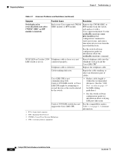
... GBIC or SFP module from the error-disabled state. connected properly. Repair the cable trunking, or select an alternative pair of cables. Cisco LRE CPE is inserted. Table 1-1 on page 1-9 for LRE cabling guidelines.) • See the switch software configuration guide for information about the errdisable recovery command. CPE = customer premises equipment Catalyst 2950 Switch Hardware Installation Guide 3-4 OL-6156-01 Use the errdisable recovery cause gbic-invalid global configuration command to verify port status, and enter a time interval to...
... GBIC or SFP module from the error-disabled state. connected properly. Repair the cable trunking, or select an alternative pair of cables. Cisco LRE CPE is inserted. Table 1-1 on page 1-9 for LRE cabling guidelines.) • See the switch software configuration guide for information about the errdisable recovery command. CPE = customer premises equipment Catalyst 2950 Switch Hardware Installation Guide 3-4 OL-6156-01 Use the errdisable recovery cause gbic-invalid global configuration command to verify port status, and enter a time interval to...

Hardware Installation Guide
Page 119
... Setup mode, follow the steps described in the getting started guide for a standalone switch. OL-6156-01 Catalyst 2950 Switch Hardware Installation Guide D-1 For installation procedures on the rear panel of your switch, connecting to the Gigabit Ethernet Interface Converter (GBIC) modules, or connecting to determine the release. Starting the Terminal-Emulation Software, page D-4 5. Entering the Initial Configuration Information, page D-5 Accessing the CLI For an unconfigured switch, you are installing an unconfigured switch, see the Cisco IOS release label on rack-mounting...
... Setup mode, follow the steps described in the getting started guide for a standalone switch. OL-6156-01 Catalyst 2950 Switch Hardware Installation Guide D-1 For installation procedures on the rear panel of your switch, connecting to the Gigabit Ethernet Interface Converter (GBIC) modules, or connecting to determine the release. Starting the Terminal-Emulation Software, page D-4 5. Entering the Initial Configuration Information, page D-5 Accessing the CLI For an unconfigured switch, you are installing an unconfigured switch, see the Cisco IOS release label on rack-mounting...
Hardware Installation Guide
Page 125
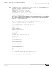
...-01 Catalyst 2950 Switch Hardware Installation Guide D-7 This is an example of the switch, and the switch displays that appears: The following configuration command script was created: hostname host_name enable secret 5 $1$Max7$Qgr9eXBhtcBJw3KK7bc850 enable password my line vty 0 15 password my_password snmp-server community public ! interface Vlan2 shutdown no ip routing ! To configure it as a member switch or as a standalone switch. interface FastEthernet0/2 ! ... !!! Would you enter N, the switch appears as a command switch later through the CLI, the device manager, or...
...-01 Catalyst 2950 Switch Hardware Installation Guide D-7 This is an example of the switch, and the switch displays that appears: The following configuration command script was created: hostname host_name enable secret 5 $1$Max7$Qgr9eXBhtcBJw3KK7bc850 enable password my line vty 0 15 password my_password snmp-server community public ! interface Vlan2 shutdown no ip routing ! To configure it as a member switch or as a standalone switch. interface FastEthernet0/2 ! ... !!! Would you enter N, the switch appears as a command switch later through the CLI, the device manager, or...

Hardware Installation Guide
Page 128
...2950ST-24 LRE 997 service warning C-1 cautions, defined x chassis warnings rack-mounting, servicing 3-7 Cisco IE2100 2-25 Cisco IE2100 Series Configuration Registrar See Cisco IE2100 IN-2 Catalyst 2950 Switch Hardware Installation Guide Cisco Intelligent Engine 2100 See Cisco IE2100 CiscoView 2-24 clearance 3-5 CLI 2-24 accessing by using Express Setup D-1 accessing through console port D-2 Coarse Wave Division Multiplexing GBIC modules See CWDM GBIC modules command-line interface See CLI configuration examples, network 2-1 configuring ports 3-40 connecting to 10/100/1000 ports 3-27 to 3-28...
...2950ST-24 LRE 997 service warning C-1 cautions, defined x chassis warnings rack-mounting, servicing 3-7 Cisco IE2100 2-25 Cisco IE2100 Series Configuration Registrar See Cisco IE2100 IN-2 Catalyst 2950 Switch Hardware Installation Guide Cisco Intelligent Engine 2100 See Cisco IE2100 CiscoView 2-24 clearance 3-5 CLI 2-24 accessing by using Express Setup D-1 accessing through console port D-2 Coarse Wave Division Multiplexing GBIC modules See CWDM GBIC modules command-line interface See CLI configuration examples, network 2-1 configuring ports 3-40 connecting to 10/100/1000 ports 3-27 to 3-28...
Hardware Installation Guide
Page 132
..., GBIC module ports, LRE, and console ports POST problems, solving 4-3 POTS splitters, limitations and restrictions 3-31 power agency approvals A-7 connecting to DC C-1 to C-7 requirements A-1 to A-4 supply AC connector 2-22 DC connector 2-23 RPS connector 2-23 power connectors 2-22 to 2-23 procedures connecting to DC power C-1 to C-7 connection 3-27 to 3-40 installation 3-7 to 3-18 IP address 3-40 publications, related xv to xvi IN-6 Catalyst 2950 Switch Hardware Installation Guide R rack-mounting bracket mounting points...
..., GBIC module ports, LRE, and console ports POST problems, solving 4-3 POTS splitters, limitations and restrictions 3-31 power agency approvals A-7 connecting to DC C-1 to C-7 requirements A-1 to A-4 supply AC connector 2-22 DC connector 2-23 RPS connector 2-23 power connectors 2-22 to 2-23 procedures connecting to DC power C-1 to C-7 connection 3-27 to 3-40 installation 3-7 to 3-18 IP address 3-40 publications, related xv to xvi IN-6 Catalyst 2950 Switch Hardware Installation Guide R rack-mounting bracket mounting points...


