
Brochure
Page 1
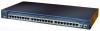
... 2 Gigabit Interface Converter (GBIC)-based Gigabit Ethernet ports • Cisco Catalyst 2950G 24-24 10/100 ports and 2 GBIC ports • Cisco Catalyst 2950G 24-DC-24 10/100 ports, 2 GBIC ports, DC power • Cisco Catalyst 2950G 12-12 10/100 ports and 2 GBIC ports • Cisco Catalyst 2950T 24-24 10/100 ports and 2 fixed 10/100/1000BASE-T uplink ports...
... 2 Gigabit Interface Converter (GBIC)-based Gigabit Ethernet ports • Cisco Catalyst 2950G 24-24 10/100 ports and 2 GBIC ports • Cisco Catalyst 2950G 24-DC-24 10/100 ports, 2 GBIC ports, DC power • Cisco Catalyst 2950G 12-12 10/100 ports and 2 GBIC ports • Cisco Catalyst 2950T 24-24 10/100 ports and 2 fixed 10/100/1000BASE-T uplink ports...
Brochure
Page 2
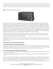
...voice and data network is attainable when a Cisco Catalyst 2950 Switch is the only company with redundant uplinks. Cisco is combined with Standard Image Software The Cisco Catalyst 2950SX-48-SI, 2950T-48-SI, 2950SX-24, 2950-24 and 2950-12 are standalone, fixed-configuration, managed 10/... over copper allows network managers to 5000 feet. Figure 1. can also be found on the Cisco Catalyst 2950G-12, 2950G-24 and 2950G-48 accommodate several GBIC transceivers, including the Cisco GigaStack®, 1000BASE-SX, 1000BASE-LX/LH, 1000BASE-ZX, 1000BASE-T, and coarse wavelength-division ...
...voice and data network is attainable when a Cisco Catalyst 2950 Switch is the only company with redundant uplinks. Cisco is combined with Standard Image Software The Cisco Catalyst 2950SX-48-SI, 2950T-48-SI, 2950SX-24, 2950-24 and 2950-12 are standalone, fixed-configuration, managed 10/... over copper allows network managers to 5000 feet. Figure 1. can also be found on the Cisco Catalyst 2950G-12, 2950G-24 and 2950G-48 accommodate several GBIC transceivers, including the Cisco GigaStack®, 1000BASE-SX, 1000BASE-LX/LH, 1000BASE-ZX, 1000BASE-T, and coarse wavelength-division ...

Brochure
Page 11
... (Catalyst 2950G-24, 2950G-24-DC, 2950T-24, 2950C-24, 2950G-12) • Cisco Catalyst 2950G-48: 13.6 Gbps maximum forwarding bandwidth • Cisco Catalyst 2950G-24: 8.8 Gbps maximum forwarding bandwidth • Cisco Catalyst 2950G-24-DC: 8.8 Gbps maximum forwarding bandwidth • Cisco Catalyst 2950G-12: 6.4 Gbps maximum forwarding bandwidth • Cisco Catalyst 2950T-24: 8.8 Gbps maximum forwarding bandwidth • Cisco Catalyst 2950C-24: 5.2 Gbps maximum...
... (Catalyst 2950G-24, 2950G-24-DC, 2950T-24, 2950C-24, 2950G-12) • Cisco Catalyst 2950G-48: 13.6 Gbps maximum forwarding bandwidth • Cisco Catalyst 2950G-24: 8.8 Gbps maximum forwarding bandwidth • Cisco Catalyst 2950G-24-DC: 8.8 Gbps maximum forwarding bandwidth • Cisco Catalyst 2950G-12: 6.4 Gbps maximum forwarding bandwidth • Cisco Catalyst 2950T-24: 8.8 Gbps maximum forwarding bandwidth • Cisco Catalyst 2950C-24: 5.2 Gbps maximum...

Brochure
Page 12
All rights reserved. Page 12 of Cisco Systems, Inc. can be found on 10BASE-T, 100BASE-TX, and 1000BASE-T ports • IEEE 802.1D Spanning-Tree Protocol • IEEE 802.1p class-of-...-MIB • IANAifType-MIB • IF-MIB (RFC 1573) • OLD-CISCO-CHASSIS-MIB • OLD-CISCO-CPU-MIB • OLD-CISCO-INTERFACES-MIB • OLD-CISCO-IP-MIB • OLD-CISCO-MEMORY-MIB • OLD-CISCO-SYSTEM-MIB • OLD-CISCO-TCP-MIB • OLD-CISCO-TS-MIB • RFC1213-MIB (MIB-II) • RFC1398-MIB (ETHERNET...
All rights reserved. Page 12 of Cisco Systems, Inc. can be found on 10BASE-T, 100BASE-TX, and 1000BASE-T ports • IEEE 802.1D Spanning-Tree Protocol • IEEE 802.1p class-of-...-MIB • IANAifType-MIB • IF-MIB (RFC 1573) • OLD-CISCO-CHASSIS-MIB • OLD-CISCO-CPU-MIB • OLD-CISCO-INTERFACES-MIB • OLD-CISCO-IP-MIB • OLD-CISCO-MEMORY-MIB • OLD-CISCO-SYSTEM-MIB • OLD-CISCO-TCP-MIB • OLD-CISCO-TS-MIB • RFC1213-MIB (MIB-II) • RFC1398-MIB (ETHERNET...
Brochure
Page 14
..., preventing loss of 30°C: • WS-C2950-24, WS-C2950-12, WS-C2950C-24, and WS-C2950T-24: 46 dBa • WS-C2950G-12, WS-C2950G-24: 46 dBa • WS-C2950G-48: 48 dBa • 482,776 hours (Cisco Catalyst 2950G-12) • 475,184 hours (Cisco Catalyst 2950G-24) • 479,086 hours (Cisco Catalyst 2950G-24-DC) • 256,446 hours (Cisco Catalyst 2950G-48) • 574,284...
..., preventing loss of 30°C: • WS-C2950-24, WS-C2950-12, WS-C2950C-24, and WS-C2950T-24: 46 dBa • WS-C2950G-12, WS-C2950G-24: 46 dBa • WS-C2950G-48: 48 dBa • 482,776 hours (Cisco Catalyst 2950G-12) • 475,184 hours (Cisco Catalyst 2950G-24) • 479,086 hours (Cisco Catalyst 2950G-24-DC) • 256,446 hours (Cisco Catalyst 2950G-48) • 574,284...

Brochure
Page 16
... of ownership by using Cisco expertise and knowledge • Minimizes network downtime ORDERING INFORMATION Model Numbers Configuration WS-C2950G-48-EI • 48 10/100 ports + two 1000BASE-X ports • Enhanced Image software installed WS-C2950G-24-EI • 24 10/100 ports + ... • Enhanced Image software installed WS-C2950G-12-EI • 12 10/100 ports + two 1000BASE-X ports • Enhanced Image software installed WS-C2950T-24 • 24 10/100 ports + two 1000BASE-T ports • Enhanced Image software installed WS-C2950C-24 • 24 10/100 ports + two 100BASE-...
... of ownership by using Cisco expertise and knowledge • Minimizes network downtime ORDERING INFORMATION Model Numbers Configuration WS-C2950G-48-EI • 48 10/100 ports + two 1000BASE-X ports • Enhanced Image software installed WS-C2950G-24-EI • 24 10/100 ports + ... • Enhanced Image software installed WS-C2950G-12-EI • 12 10/100 ports + two 1000BASE-X ports • Enhanced Image software installed WS-C2950T-24 • 24 10/100 ports + two 1000BASE-T ports • Enhanced Image software installed WS-C2950C-24 • 24 10/100 ports + two 100BASE-...

Hardware Installation Guide
Page 12
... Points and Bridges, versions 12.4(10b) JA and 12.3(8) JEC • Wireless LAN Controllers • Unified Wireless LAN Access Points Voice • Cisco IOS Voice Port Configuration Guide • SCCP Controlled Analog (FXS) Ports with Supplementary Features in Cisco 15.0(1)M Note Cisco IOS software release 15.0(1)M is the next IOS release following the Cisco IOS 12.4(24)T release.
... Points and Bridges, versions 12.4(10b) JA and 12.3(8) JEC • Wireless LAN Controllers • Unified Wireless LAN Access Points Voice • Cisco IOS Voice Port Configuration Guide • SCCP Controlled Analog (FXS) Ports with Supplementary Features in Cisco 15.0(1)M Note Cisco IOS software release 15.0(1)M is the next IOS release following the Cisco IOS 12.4(24)T release.
Hardware Installation Guide
Page 15
...Routers 1-1 Chassis Views 1-2 Cisco 2901 Chassis 1-2 Cisco 2911 Chassis 1-4 Cisco 2921 and Cisco 2951 Chassis 1-6 Cisco 3900 Series Chassis 1-8 Locating the Serial Number, PID, VID and CLEI 1-12 Labels on Cisco 2901 1-13 Labels on Cisco 2911 1-14 Labels on Cisco 2921 and Cisco 2951 1-14 Labels on Cisco 3925 and Cisco 3945 1-15 For Additional... 1-21 Packet Voice Data Modules 1-21 Memory 1-21 Power Supplies 1-23 Module and Router Power Consumption 1-24 Fans, Ventilation, and Airflow 1-24 Real-Time Clock 1-26 Secure Key 1-27 Cryptographic Accelerator 1-27 Slot, Port, and Interface Information 1-27...
...Routers 1-1 Chassis Views 1-2 Cisco 2901 Chassis 1-2 Cisco 2911 Chassis 1-4 Cisco 2921 and Cisco 2951 Chassis 1-6 Cisco 3900 Series Chassis 1-8 Locating the Serial Number, PID, VID and CLEI 1-12 Labels on Cisco 2901 1-13 Labels on Cisco 2911 1-14 Labels on Cisco 2921 and Cisco 2951 1-14 Labels on Cisco 3925 and Cisco 3945 1-15 For Additional... 1-21 Packet Voice Data Modules 1-21 Memory 1-21 Power Supplies 1-23 Module and Router Power Consumption 1-24 Fans, Ventilation, and Airflow 1-24 Real-Time Clock 1-26 Secure Key 1-27 Cryptographic Accelerator 1-27 Slot, Port, and Interface Information 1-27...

Hardware Installation Guide
Page 16
...-Mounting the Chassis 3-5 Attaching Rack-Mount Brackets to Cisco 2901 Routers 3-5 Attaching Rack-Mount Brackets to Cisco 2911, Cisco 2921, and Cisco 2951 Routers 3-6 Attaching Rack-Mount Brackets to Cisco 3900 Series Routers 3-8 Mounting the Router in a Rack 3-10 Grounding the Chassis 3-12 Setting the Chassis on a Desktop 3-12 Mounting a Cisco 2901 or 2911 Router on a Wall 3-13...
...-Mounting the Chassis 3-5 Attaching Rack-Mount Brackets to Cisco 2901 Routers 3-5 Attaching Rack-Mount Brackets to Cisco 2911, Cisco 2921, and Cisco 2951 Routers 3-6 Attaching Rack-Mount Brackets to Cisco 3900 Series Routers 3-8 Mounting the Router in a Rack 3-10 Grounding the Chassis 3-12 Setting the Chassis on a Desktop 3-12 Mounting a Cisco 2901 or 2911 Router on a Wall 3-13...

Hardware Installation Guide
Page 21
... Communications Manager Express (CUCME) via Cisco IOS. A logical GE interface on hardware. Additional security features are provided in this chapter: • Chassis Views, page 1-2 • Locating the Serial Number, PID, VID and CLEI, page 1-12 • Hardware Features, page 1-16 ...• Slot, Port, and Interface Information, page 1-27 • LED Indicators, page 1-29 • Specifications, page 1-32 Cisco 2900 Series and 3900 Series Hardware Installation Guide 1-1 1 C H A P...
... Communications Manager Express (CUCME) via Cisco IOS. A logical GE interface on hardware. Additional security features are provided in this chapter: • Chassis Views, page 1-2 • Locating the Serial Number, PID, VID and CLEI, page 1-12 • Hardware Features, page 1-16 ...• Slot, Port, and Interface Information, page 1-27 • LED Indicators, page 1-29 • Specifications, page 1-32 Cisco 2900 Series and 3900 Series Hardware Installation Guide 1-1 1 C H A P...

Hardware Installation Guide
Page 24
...on page 1-5- ISM = Internal Services Module 23 45 2 ISM1 4 EN (Enable USB console) 6 S (Speed) L 2901 Cisco 2911 Chassis Figure 1-4- Front panel Figure 1-5 on page 1-6 - Back panel LEDs Figure 1-4 Front Panel of the Routers 67 EHWIC... 1 (0, Right) 3 PVDM3 0 and 1 (0, Right) 5 EN (Enable RJ-45 console) 7 L (Link) 1. 250962 Chassis Views Figure 1-3 Back Panel LEDs of Cisco 2901 Router Chapter 1 Overview of the Cisco 2911 Router 4 5 6 7 8 SYS ACT POE RPS PS Cisco 2900 Series 250971 12 3 1 AC OK1 3 AC power connector 5 ACT 7 RPS2 9 Optional RPS adapter (blank panel shown...
...on page 1-5- ISM = Internal Services Module 23 45 2 ISM1 4 EN (Enable USB console) 6 S (Speed) L 2901 Cisco 2911 Chassis Figure 1-4- Front panel Figure 1-5 on page 1-6 - Back panel LEDs Figure 1-4 Front Panel of the Routers 67 EHWIC... 1 (0, Right) 3 PVDM3 0 and 1 (0, Right) 5 EN (Enable RJ-45 console) 7 L (Link) 1. 250962 Chassis Views Figure 1-3 Back Panel LEDs of Cisco 2901 Router Chapter 1 Overview of the Cisco 2911 Router 4 5 6 7 8 SYS ACT POE RPS PS Cisco 2900 Series 250971 12 3 1 AC OK1 3 AC power connector 5 ACT 7 RPS2 9 Optional RPS adapter (blank panel shown...

Hardware Installation Guide
Page 25
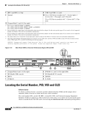
...: WARNING: Unsupported compact flash detected. Legacy CF can impact and several degrade performance in Cisco 2900 series and Cisco 3900 series ISRs. OL-18712-02 Cisco 2900 Series and 3900 Series Hardware Installation Guide 1-5 EHWIC slots support HWIC, VIC, and... for a list of the Cisco 2911 Router 1 EHWIC 3 EHWIC 2 EHWIC 1 DO NOT REMOVE DURING NETWORKING OPERATION CF 1 DO NOT REMOVE DURING NETWORKING OPERATION CF 0 ISM PVDM1 PVDM0 EHWIC 0 2 34 65 9 7 8 S L AUX GE 0/2 G S L E 0 / 0 1 USB EN EN 0 CONSOLE GE 0/1 2911 12 13 12 11 10 1 EHWIC slots1 0, 1,...
...: WARNING: Unsupported compact flash detected. Legacy CF can impact and several degrade performance in Cisco 2900 series and Cisco 3900 series ISRs. OL-18712-02 Cisco 2900 Series and 3900 Series Hardware Installation Guide 1-5 EHWIC slots support HWIC, VIC, and... for a list of the Cisco 2911 Router 1 EHWIC 3 EHWIC 2 EHWIC 1 DO NOT REMOVE DURING NETWORKING OPERATION CF 1 DO NOT REMOVE DURING NETWORKING OPERATION CF 0 ISM PVDM1 PVDM0 EHWIC 0 2 34 65 9 7 8 S L AUX GE 0/2 G S L E 0 / 0 1 USB EN EN 0 CONSOLE GE 0/1 2911 12 13 12 11 10 1 EHWIC slots1 0, 1,...

Hardware Installation Guide
Page 28
...Engines (SPEs) pre-installed in the router. Figure 1-13 • Back panel LEDs- Chassis Views Figure 1-9 Back Panel LEDS of the Cisco 2921 and 2951 Routers Chapter 1 Overview of the Routers 8 9 250901 EHWIC 3 EHWIC 2 EHWIC 1 DO NOT REMOVE DURING NETWORKING OPERATION CF... the "Services Performance Engine" section on page 1-20 for models and support information. Figure 1-12 Cisco 3925E and Cisco 3945E (SPE 200 or SPE 250) • Back panel slots and connectors- Figure 1-14 Cisco 2900 Series and 3900 Series Hardware Installation Guide 1-8 OL-18712-02 Figure 1-11 • Back...
...Engines (SPEs) pre-installed in the router. Figure 1-13 • Back panel LEDs- Chassis Views Figure 1-9 Back Panel LEDS of the Cisco 2921 and 2951 Routers Chapter 1 Overview of the Routers 8 9 250901 EHWIC 3 EHWIC 2 EHWIC 1 DO NOT REMOVE DURING NETWORKING OPERATION CF... the "Services Performance Engine" section on page 1-20 for models and support information. Figure 1-12 Cisco 3925E and Cisco 3945E (SPE 200 or SPE 250) • Back panel slots and connectors- Figure 1-14 Cisco 2900 Series and 3900 Series Hardware Installation Guide 1-8 OL-18712-02 Figure 1-11 • Back...

Hardware Installation Guide
Page 29
It does not go on and off if the AC power fails or is disconnected. PS1 3 247132 OL-18712-02 Cisco 2900 Series and 3900 Series Hardware Installation Guide 1-9 LED goes off with the power switch. Chapter 1 Overview of the Routers Figure 1-10 Front Panel of the Cisco 3900 Series ISRs 4567 8 SYS ACT POE BOOST PS2 PS1 Chassis Views Cisco 3900 Series PS2 1 2 3 12 1 AC OK1 2 On/off switch 3 Power connector 4 SYS status LED 5 ACT status LED 6 POE 7 Boost 8 PS1 (Right), PS2 (Left) 1.
It does not go on and off if the AC power fails or is disconnected. PS1 3 247132 OL-18712-02 Cisco 2900 Series and 3900 Series Hardware Installation Guide 1-9 LED goes off with the power switch. Chapter 1 Overview of the Routers Figure 1-10 Front Panel of the Cisco 3900 Series ISRs 4567 8 SYS ACT POE BOOST PS2 PS1 Chassis Views Cisco 3900 Series PS2 1 2 3 12 1 AC OK1 2 On/off switch 3 Power connector 4 SYS status LED 5 ACT status LED 6 POE 7 Boost 8 PS1 (Right), PS2 (Left) 1.

Hardware Installation Guide
Page 31
GE 0/0, Bottom) 247133 OL-18712-02 Cisco 2900 Series and 3900 Series Hardware Installation Guide 1-11 250918 Chapter 1 Overview of the Routers Chassis Views Figure 1-12 Back Panel LEDS on Services Performance Engine 100 and SPE 150 8 9 EHWIC 3 DO NOT REMOVE DURING CF1 NETWORKING ...GE 0/1, Top; ISM = Internal Services Module 2 ISM1 4 EN (Enable USB console) 6 SFP S 8 S (Speed) Figure 1-13 Back Panel Slots/Connectors for Cisco 3925E and 3945E (SPE 200 or SPE 250) 1 2 345 6 7 EHWIC 2 DO NOT REMOVE DURING NETWORKING OPERATION CF 1 EHWIC 1 DO NOT REMOVE DURING NETWORKING...
GE 0/0, Bottom) 247133 OL-18712-02 Cisco 2900 Series and 3900 Series Hardware Installation Guide 1-11 250918 Chapter 1 Overview of the Routers Chassis Views Figure 1-12 Back Panel LEDS on Services Performance Engine 100 and SPE 150 8 9 EHWIC 3 DO NOT REMOVE DURING CF1 NETWORKING ...GE 0/1, Top; ISM = Internal Services Module 2 ISM1 4 EN (Enable USB console) 6 SFP S 8 S (Speed) Figure 1-13 Back Panel Slots/Connectors for Cisco 3925E and 3945E (SPE 200 or SPE 250) 1 2 345 6 7 EHWIC 2 DO NOT REMOVE DURING NETWORKING OPERATION CF 1 EHWIC 1 DO NOT REMOVE DURING NETWORKING...
Hardware Installation Guide
Page 32
...the device where the license will not operate in Cisco 2900 series and Cisco 3900 series ISRs. Service module slots support legacy network modules when inserted with an adapter. One single-wide in privileged Exec 1-12 Cisco 2900 Series and 3900 Series Hardware Installation Guide OL...-18712-02 Only Advanced Capability CF purchased from Cisco operates in these routers. See Table 1-5 for router slot and module configurations. ...
...the device where the license will not operate in Cisco 2900 series and Cisco 3900 series ISRs. Service module slots support legacy network modules when inserted with an adapter. One single-wide in privileged Exec 1-12 Cisco 2900 Series and 3900 Series Hardware Installation Guide OL...-18712-02 Only Advanced Capability CF purchased from Cisco operates in these routers. See Table 1-5 for router slot and module configurations. ...

Hardware Installation Guide
Page 47
... numbering format for credential storage by accepting credentials and never returning them. On the Cisco 2911, 2921, 2951, and Cisco 3900 series routers, some slots are built into the chassis. Slot, Port, and Interface Information Table 1-11 and Table 1-12 show slot, port, and interface numbering ranges. name-Gi 0/0 service-module- - Chapter 1 Overview...
... numbering format for credential storage by accepting credentials and never returning them. On the Cisco 2911, 2921, 2951, and Cisco 3900 series routers, some slots are built into the chassis. Slot, Port, and Interface Information Table 1-11 and Table 1-12 show slot, port, and interface numbering ranges. name-Gi 0/0 service-module- - Chapter 1 Overview...

Hardware Installation Guide
Page 48
... associated with interface serial 0/1/0 on a WIC-2AM in slot 2. 2. Applies only to Cisco 2951, Cisco 3925, and Cisco 3925E routers. 8. Applies only to Cisco 2921 router. 5. Table 1-12 Interface Numbering on SM interfaces interface1wic-slot/port interface1-2/wicslot/port7 interface1-4/wicslot/port8 interface1-2/wicslot... associated with an asynchronous interface, use the interface number to Cisco 3945 and Cisco 3945E routers. 7. Applies only to specify the async line. Applies only to Cisco 2951, Cisco 3925, and Cisco 3925E routers. 6. FXS/FXO port numbers 16 to 15 are...
... associated with interface serial 0/1/0 on a WIC-2AM in slot 2. 2. Applies only to Cisco 2951, Cisco 3925, and Cisco 3925E routers. 8. Applies only to Cisco 2921 router. 5. Table 1-12 Interface Numbering on SM interfaces interface1wic-slot/port interface1-2/wicslot/port7 interface1-4/wicslot/port8 interface1-2/wicslot... associated with an asynchronous interface, use the interface number to Cisco 3945 and Cisco 3945E routers. 7. Applies only to specify the async line. Applies only to Cisco 2951, Cisco 3925, and Cisco 3925E routers. 6. FXS/FXO port numbers 16 to 15 are...

Hardware Installation Guide
Page 49
...is on the removable modules or interface cards. System is not running . Chapter 1 Overview of the Routers LED Indicators Table 1-12 Interface Numbering on an NM-32A in network module slot 1. interface bri 2/x 1. other types of LEDs in removable modules and...supply is the same for asynchronous interfaces as for the associated asynchronous serial interface. 5. Specify the line number in expansion module 0. Cisco 2900 Routers Front bezel - - For LED troubleshooting information, including possible trouble causes and corrective actions, see the applicable documentation for ...
...is on the removable modules or interface cards. System is not running . Chapter 1 Overview of the Routers LED Indicators Table 1-12 Interface Numbering on an NM-32A in network module slot 1. interface bri 2/x 1. other types of LEDs in removable modules and...supply is the same for asynchronous interfaces as for the associated asynchronous serial interface. 5. Specify the line number in expansion module 0. Cisco 2900 Routers Front bezel - - For LED troubleshooting information, including possible trouble causes and corrective actions, see the applicable documentation for ...

Hardware Installation Guide
Page 54
... SD/EMI EN61000-6-1 For detailed compliance information, see the Regulatory Compliance and Safety Information for Cisco 2900 Series Integrated Services Routers document. with AC-POE PS (w/o modules) With DC PS (w/o modules) Specification 3.5 x 17.25 x 12.0 in. (44.5 x 438.2 x 304.8mm), 2 RU height 18.0 lbs (8....16 kg) 19.0 lbs (8.62 kg) NA 1-34 Cisco 2900 Series and 3900 Series Hardware Installation Guide OL-18712-02 Specifications Chapter 1 Overview of...
... SD/EMI EN61000-6-1 For detailed compliance information, see the Regulatory Compliance and Safety Information for Cisco 2900 Series Integrated Services Routers document. with AC-POE PS (w/o modules) With DC PS (w/o modules) Specification 3.5 x 17.25 x 12.0 in. (44.5 x 438.2 x 304.8mm), 2 RU height 18.0 lbs (8....16 kg) 19.0 lbs (8.62 kg) NA 1-34 Cisco 2900 Series and 3900 Series Hardware Installation Guide OL-18712-02 Specifications Chapter 1 Overview of...
