Brochure
Page 2
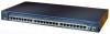
.../100 switches providing basic workgroup connectivity for protection against internal power supply failures and an uninterruptable power supply (UPS) system to Gigabit Ethernet. In addition, the Cisco Catalyst 2950T-24 offers small and medium-sized enterprises server connectivity and an easy migration path to © 2004 Cisco Systems, Inc. These wire-speed desktop switches come with the...
.../100 switches providing basic workgroup connectivity for protection against internal power supply failures and an uninterruptable power supply (UPS) system to Gigabit Ethernet. In addition, the Cisco Catalyst 2950T-24 offers small and medium-sized enterprises server connectivity and an easy migration path to © 2004 Cisco Systems, Inc. These wire-speed desktop switches come with the...

Brochure
Page 9
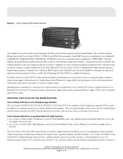
... the source device to a destination device. • Crash information support enables switches to generate a crash file for system, redundant power supply, and bandwidth utilization, provide a comprehensive and convenient visual management system. • Cisco Network Assistant Software is provided to restrict unauthorized access to servers and networks, and to restrict certain applications on the...
... the source device to a destination device. • Crash information support enables switches to generate a crash file for system, redundant power supply, and bandwidth utilization, provide a comprehensive and convenient visual management system. • Cisco Network Assistant Software is provided to restrict unauthorized access to servers and networks, and to restrict certain applications on the...
Brochure
Page 14
... of 30°C: • WS-C2950-24, WS-C2950-12, WS-C2950C-24, and WS-C2950T-24: 46 dBa • WS-C2950G-12, WS-C2950G-24: 46 dBa • WS-C2950G-48: 48 dBa • 482,776 hours (Cisco Catalyst 2950G-12) • 475,184 hours (Cisco Catalyst 2950G-24) • 479,086 hours (Cisco Catalyst 2950G-24-DC) • 256,446 hours (Cisco Catalyst 2950G-48) • 574...
... of 30°C: • WS-C2950-24, WS-C2950-12, WS-C2950C-24, and WS-C2950T-24: 46 dBa • WS-C2950G-12, WS-C2950G-24: 46 dBa • WS-C2950G-48: 48 dBa • 482,776 hours (Cisco Catalyst 2950G-12) • 475,184 hours (Cisco Catalyst 2950G-24) • 479,086 hours (Cisco Catalyst 2950G-24-DC) • 256,446 hours (Cisco Catalyst 2950G-48) • 574...
Hardware Installation Guide
Page 15
...1-1 Chassis Views 1-2 Cisco 2901 Chassis 1-2 Cisco 2911 Chassis 1-4 Cisco 2921 and Cisco 2951 Chassis 1-6 Cisco 3900 Series Chassis 1-8 Locating the Serial Number, PID, VID and CLEI 1-12 Labels on Cisco 2901 1-13 Labels on Cisco 2911 1-14 Labels on Cisco 2921 and Cisco 2951 1-14 Labels on Cisco 3925 and Cisco 3945 1-15 For...Interface Cards 1-20 Integrated Service Modules 1-21 Packet Voice Data Modules 1-21 Memory 1-21 Power Supplies 1-23 Module and Router Power Consumption 1-24 Fans, Ventilation, and Airflow 1-24 Real-Time Clock 1-26 Secure Key 1-27 Cryptographic Accelerator 1-27 Slot, Port, and...
...1-1 Chassis Views 1-2 Cisco 2901 Chassis 1-2 Cisco 2911 Chassis 1-4 Cisco 2921 and Cisco 2951 Chassis 1-6 Cisco 3900 Series Chassis 1-8 Locating the Serial Number, PID, VID and CLEI 1-12 Labels on Cisco 2901 1-13 Labels on Cisco 2911 1-14 Labels on Cisco 2921 and Cisco 2951 1-14 Labels on Cisco 3925 and Cisco 3945 1-15 For...Interface Cards 1-20 Integrated Service Modules 1-21 Packet Voice Data Modules 1-21 Memory 1-21 Power Supplies 1-23 Module and Router Power Consumption 1-24 Fans, Ventilation, and Airflow 1-24 Real-Time Clock 1-26 Secure Key 1-27 Cryptographic Accelerator 1-27 Slot, Port, and...

Hardware Installation Guide
Page 17
... Scenarios Not Approved for Dual DC Power Supply Configuration on Cisco 2911, 2921, and 2951 Routers 3-23 DC Wiring Requirements for Cisco 3900 Series Routers 3-25 Cisco 3900 Series Router Wiring Procedure for DC Input 3-26 Dual DC Power Supply Configuration in Cisco 3925 and Cisco 3925-NOVPN Routers 3-28 Connecting to Backup Power 3-31 Connecting to a Console Terminal or...
... Scenarios Not Approved for Dual DC Power Supply Configuration on Cisco 2911, 2921, and 2951 Routers 3-23 DC Wiring Requirements for Cisco 3900 Series Routers 3-25 Cisco 3900 Series Router Wiring Procedure for DC Input 3-26 Dual DC Power Supply Configuration in Cisco 3925 and Cisco 3925-NOVPN Routers 3-28 Connecting to Backup Power 3-31 Connecting to a Console Terminal or...

Hardware Installation Guide
Page 18
... Your Router Configuration 4-22 Saving Backup Copies of Configuration and System Image 4-22 Verifying the Initial Configuration 4-24 Installing and Upgrading Internal Modules and FRUs 5-1 Safety Warnings 5-2 Accessing Internal Modules 5-4 Removing and Replacing the...22 Installing and Removing PVDM2s 5-23 Replacing Power Supplies and Redundant Power Supplies 5-28 Replacing the Cisco 2901 Router Power Supply 5-30 Replacing the Cisco 2911 Router Power Supply 5-32 Installing and Removing the Cisco 2911 Router Optional DC Power Supply 5-33 Cisco 2900 Series and 3900 Series Hardware Installation ...
... Your Router Configuration 4-22 Saving Backup Copies of Configuration and System Image 4-22 Verifying the Initial Configuration 4-24 Installing and Upgrading Internal Modules and FRUs 5-1 Safety Warnings 5-2 Accessing Internal Modules 5-4 Removing and Replacing the...22 Installing and Removing PVDM2s 5-23 Replacing Power Supplies and Redundant Power Supplies 5-28 Replacing the Cisco 2901 Router Power Supply 5-30 Replacing the Cisco 2911 Router Power Supply 5-32 Installing and Removing the Cisco 2911 Router Optional DC Power Supply 5-33 Cisco 2900 Series and 3900 Series Hardware Installation ...

Hardware Installation Guide
Page 19
... the 2911 DC Power Supply 5-33 Removing the 2911 DC Power Supply 5-34 Installing the Cisco 2911 Router Power Supply Blank 5-34 Replacing the Cisco 2911 Router Redundant Power Supply 5-36 Replacing the Cisco 2921, Cisco 2951, or Cisco 3900 Series Power Supply 5-36 Replacing the Power Supply on the Cisco 2921 and Cisco 2951 Routers 5-37 Replacing the Power Supply on the Cisco 3900 Series Routers 5-38 Inserting POE supply in an...
... the 2911 DC Power Supply 5-33 Removing the 2911 DC Power Supply 5-34 Installing the Cisco 2911 Router Power Supply Blank 5-34 Replacing the Cisco 2911 Router Redundant Power Supply 5-36 Replacing the Cisco 2921, Cisco 2951, or Cisco 3900 Series Power Supply 5-36 Replacing the Power Supply on the Cisco 2921 and Cisco 2951 Routers 5-37 Replacing the Power Supply on the Cisco 3900 Series Routers 5-38 Inserting POE supply in an...

Hardware Installation Guide
Page 25
... Capability CompactFlash (CF) purchased from Cisco operates in these routers. See the "Memory" section on and off if the AC power fails or is inserted, the following error message appears: WARNING: Unsupported compact flash detected. PS = power supply Figure 1-5 Back Panel of the ...Routers Chassis Views 1. Please use supported compact flash cards only. 3. RPS = Redundant Power Supply 3. EHWIC slots support HWIC, VIC, and WIC. 2. 250972 Chapter 1 Overview of the Cisco 2911 Router 1 EHWIC 3 EHWIC 2 EHWIC 1 DO NOT REMOVE DURING NETWORKING OPERATION CF 1 DO ...
... Capability CompactFlash (CF) purchased from Cisco operates in these routers. See the "Memory" section on and off if the AC power fails or is inserted, the following error message appears: WARNING: Unsupported compact flash detected. PS = power supply Figure 1-5 Back Panel of the ...Routers Chassis Views 1. Please use supported compact flash cards only. 3. RPS = Redundant Power Supply 3. EHWIC slots support HWIC, VIC, and WIC. 2. 250972 Chapter 1 Overview of the Cisco 2911 Router 1 EHWIC 3 EHWIC 2 EHWIC 1 DO NOT REMOVE DURING NETWORKING OPERATION CF 1 DO ...

Hardware Installation Guide
Page 27
...: WARNING: Unsupported compact flash detected. EHWIC slots support HWIC, VIC, and WIC. 2. See the router product page at Cisco.com for a list of supported modules. Power supply (PS) Figure 1-8 Back Panel Slots and Connectors on the Cisco 2921 and 2951 Routers 1 2 345 6 7 EHWIC 3 DO NOT REMOVE DURING NETWORKING OPERATION CF 1 EHWIC 2 EHWIC 1 DO NOT...
...: WARNING: Unsupported compact flash detected. EHWIC slots support HWIC, VIC, and WIC. 2. See the router product page at Cisco.com for a list of supported modules. Power supply (PS) Figure 1-8 Back Panel Slots and Connectors on the Cisco 2921 and 2951 Routers 1 2 345 6 7 EHWIC 3 DO NOT REMOVE DURING NETWORKING OPERATION CF 1 EHWIC 2 EHWIC 1 DO NOT...

Hardware Installation Guide
Page 36
... section describes the hardware features in Cisco 2900 series and Cisco 3900 series routers. • Built-in Interface Ports, page 1-16 • Removable and Interchangeable Modules and Cards, page 1-18 • Packet Voice Data Modules, page 1-21 • Power Supplies, page 1-23 • Module and Router Power Consumption, page 1-24 • Fans, Ventilation, and Airflow, page...
... section describes the hardware features in Cisco 2900 series and Cisco 3900 series routers. • Built-in Interface Ports, page 1-16 • Removable and Interchangeable Modules and Cards, page 1-18 • Packet Voice Data Modules, page 1-21 • Power Supplies, page 1-23 • Module and Router Power Consumption, page 1-24 • Fans, Ventilation, and Airflow, page...

Hardware Installation Guide
Page 43
... both must be the same density. Power Supplies Cisco 2900 series and Cisco 3900 series ISRs support a variety of the Routers Hardware Features Table 1-8 Router Memory Specifications (continued) Router Platform Cisco 3925E Cisco 3945E DRAM Type-VLP RDIMMwith ECC. Configurations...3. RPSs require an RPS adapter. X - Both use the Cisco Redundant Power System 2300. Uses external Cisco Redundant Power System 2300 with dual power supplies or an Redundant power supplies (RPS), the power supplies are field replaceable and externally accessible with and without IP), Dual ...
... both must be the same density. Power Supplies Cisco 2900 series and Cisco 3900 series ISRs support a variety of the Routers Hardware Features Table 1-8 Router Memory Specifications (continued) Router Platform Cisco 3925E Cisco 3945E DRAM Type-VLP RDIMMwith ECC. Configurations...3. RPSs require an RPS adapter. X - Both use the Cisco Redundant Power System 2300. Uses external Cisco Redundant Power System 2300 with dual power supplies or an Redundant power supplies (RPS), the power supplies are field replaceable and externally accessible with and without IP), Dual ...

Hardware Installation Guide
Page 44
...24 Cisco 2900 Series and 3900 Series Hardware Installation Guide OL-18712-02 When a filter becomes dirty, discard it and replace it with a new one of the Routers 5. Uses Cisco Redundant Power System 2300 as 100% power boost. Fans, Ventilation, and Airflow The Cisco 2911 and Cisco... 3900 series ISRs have energy efficiency features that are dependent on page 5-45. Hardware Features • High-efficiency AC power supplies. Internal power supply does not supply any boost...
...24 Cisco 2900 Series and 3900 Series Hardware Installation Guide OL-18712-02 When a filter becomes dirty, discard it and replace it with a new one of the Routers 5. Uses Cisco Redundant Power System 2300 as 100% power boost. Fans, Ventilation, and Airflow The Cisco 2911 and Cisco... 3900 series ISRs have energy efficiency features that are dependent on page 5-45. Hardware Features • High-efficiency AC power supplies. Internal power supply does not supply any boost...

Hardware Installation Guide
Page 49
...example, line 0/3/0 specifies the line associated with interface serial 0/3/0 on an WIC-2A/S in expansion module 1. External POE Boost power supply is the same for asynchronous interfaces as for the associated asynchronous serial interface. 5. Port numbers are located on the router bezel...module (EVM) Interface-type 2 / 0 / port Port numbers are used for all Cisco 2900 series routers. For descriptions of LEDs in the Cisco IOS command-line interface (CLI) by POE Boost power supply. Cisco 2900 Routers Front bezel - - voice-port 2/0/x BRI interface in a BRI expansion module ...
...example, line 0/3/0 specifies the line associated with interface serial 0/3/0 on an WIC-2A/S in expansion module 1. External POE Boost power supply is the same for asynchronous interfaces as for the associated asynchronous serial interface. 5. Port numbers are located on the router bezel...module (EVM) Interface-type 2 / 0 / port Port numbers are used for all Cisco 2900 series routers. For descriptions of LEDs in the Cisco IOS command-line interface (CLI) by POE Boost power supply. Cisco 2900 Routers Front bezel - - voice-port 2/0/x BRI interface in a BRI expansion module ...

Hardware Installation Guide
Page 50
... on 2901 Green System is running on 2901 Solid green Solid green indicates normal operation. Front bezel, not available on external RPS power supply. Solid or blinking green Solid or blinking indicates packet activity between the forwarding and routing engine and any I/O port. Green Flash ...memory is not being accessed; Back panel Off Flash memory is being Back panel accessed; Cisco 3900 Routers Front bezel Front bezel - Front bezel Blinking green System is booting or is active. Front bezel Off No packet transfers ...
... on 2901 Green System is running on 2901 Solid green Solid green indicates normal operation. Front bezel, not available on external RPS power supply. Solid or blinking green Solid or blinking indicates packet activity between the forwarding and routing engine and any I/O port. Green Flash ...memory is not being accessed; Back panel Off Flash memory is being Back panel accessed; Cisco 3900 Routers Front bezel Front bezel - Front bezel Blinking green System is booting or is active. Front bezel Off No packet transfers ...

Hardware Installation Guide
Page 67
...router. Incorrectly connecting this equipment to install, replace, or service this publication, see translated warnings that might have more than one power supply connection. Statement 1028 Warning Blank faceplates and cover panels serve three important functions: they prevent exposure to de-energize the unit....Specifications, page 2-7 • Installation Checklist, page 2-14 • Creating a Site Log, page 2-15 To see the Cisco 2900 and 3900 Series Integrated Services Routers Regulatory Compliance and Safety Information document. Do not operate the system unless all cards, ...
...router. Incorrectly connecting this equipment to install, replace, or service this publication, see translated warnings that might have more than one power supply connection. Statement 1028 Warning Blank faceplates and cover panels serve three important functions: they prevent exposure to de-energize the unit....Specifications, page 2-7 • Installation Checklist, page 2-14 • Creating a Site Log, page 2-15 To see the Cisco 2900 and 3900 Series Integrated Services Routers Regulatory Compliance and Safety Information document. Do not operate the system unless all cards, ...

Hardware Installation Guide
Page 69
... three important functions: they direct the flow of the internal power supply. • If an electrical accident occurs, proceed as moist floors, ungrounded power extension cables, frayed power cords, and missing safety grounds. • Do not work...power supplies • Look carefully for Router Installation Safety Recommendations • Do not wear loose clothing that power is disconnected from a circuit. Turn off the power. • Disconnect all cards, faceplates, front covers, and rear covers are an integral part of the safety design of lightning activity. OL-18712-02 Cisco...
... three important functions: they direct the flow of the internal power supply. • If an electrical accident occurs, proceed as moist floors, ungrounded power extension cables, frayed power cords, and missing safety grounds. • Do not work...power supplies • Look carefully for Router Installation Safety Recommendations • Do not wear loose clothing that power is disconnected from a circuit. Turn off the power. • Disconnect all cards, faceplates, front covers, and rear covers are an integral part of the safety design of lightning activity. OL-18712-02 Cisco...

Hardware Installation Guide
Page 71
...module slots, interface card slots, and power supply bays must have adequate ventilation. Power off other equipment in the rack (and in the "Preventing Electrostatic Discharge Damage" section on the airflow patterns in the rack. The Cisco 2901 router can make maintenance difficult. Electrical... the intake ports of air across internal components. • Baffles can be placed on page 2-4, section. OL-18712-02 Cisco 2900 Series and 3900 Series Hardware Installation Guide 2-5 Chapter 2 Preparing for Router Installation Router Environmental Requirements • Enclosed racks ...
...module slots, interface card slots, and power supply bays must have adequate ventilation. Power off other equipment in the rack (and in the "Preventing Electrostatic Discharge Damage" section on the airflow patterns in the rack. The Cisco 2901 router can make maintenance difficult. Electrical... the intake ports of air across internal components. • Baffles can be placed on page 2-4, section. OL-18712-02 Cisco 2900 Series and 3900 Series Hardware Installation Guide 2-5 Chapter 2 Preparing for Router Installation Router Environmental Requirements • Enclosed racks ...

Hardware Installation Guide
Page 72
... - 240 VAC 90 - 264 VAC 100 - 240 VAC 90 - 264 VAC 24 - 60 VDC 18 - 75 VDC Cisco 2900 Series and 3900 Series Hardware Installation Guide 2-6 OL-18712-02 Table 2-1 Power Requirements for the Cisco 2900 and 3900 series routers. The AC power supply includes the following features: • Autoselects either 110 V or 220 V operation. •...
... - 240 VAC 90 - 264 VAC 100 - 240 VAC 90 - 264 VAC 24 - 60 VDC 18 - 75 VDC Cisco 2900 Series and 3900 Series Hardware Installation Guide 2-6 OL-18712-02 Table 2-1 Power Requirements for the Cisco 2900 and 3900 series routers. The AC power supply includes the following features: • Autoselects either 110 V or 220 V operation. •...

Hardware Installation Guide
Page 83
... the chassis. Statement 1026 OL-18712-01 Cisco 2900 and 3900 Series Hardware Installation 3-1 they contain electromagnetic interference (EMI) that appear in WAN ports regardless of the warnings that might have more than one power supply connection. and they prevent exposure to install..., replace, or service this publication, see the Regulatory Compliance and Safety Information for Cisco 2900 Series Integrated Services Routers or the Regulatory Compliance and...
... the chassis. Statement 1026 OL-18712-01 Cisco 2900 and 3900 Series Hardware Installation 3-1 they contain electromagnetic interference (EMI) that appear in WAN ports regardless of the warnings that might have more than one power supply connection. and they prevent exposure to install..., replace, or service this publication, see the Regulatory Compliance and Safety Information for Cisco 2900 Series Integrated Services Routers or the Regulatory Compliance and...

Hardware Installation Guide
Page 93
... lift or tilt the chassis using the handles on modules (such as power supplies, fans, or cards); Figure 3-12 Mounting the Chassis in a rack to leave space above and below each router in a Rack (Typical) 250911 SYS ACT POE RPS PS Cisco 2900 Series 1 1 Mounting screws (4) Figure 3-13 shows an installation with a chassis...
... lift or tilt the chassis using the handles on modules (such as power supplies, fans, or cards); Figure 3-12 Mounting the Chassis in a rack to leave space above and below each router in a Rack (Typical) 250911 SYS ACT POE RPS PS Cisco 2900 Series 1 1 Mounting screws (4) Figure 3-13 shows an installation with a chassis...


