
Brochure
Page 1
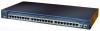
... 2 Gigabit Interface Converter (GBIC)-based Gigabit Ethernet ports • Cisco Catalyst 2950G 24-24 10/100 ports and 2 GBIC ports • Cisco Catalyst 2950G 24-DC-24 10/100 ports, 2 GBIC ports, DC power • Cisco Catalyst 2950G 12-12 10/100 ports and 2 GBIC ports • Cisco Catalyst 2950T 24-24 10/100 ports and 2 fixed 10/100/1000BASE-T uplink...
... 2 Gigabit Interface Converter (GBIC)-based Gigabit Ethernet ports • Cisco Catalyst 2950G 24-24 10/100 ports and 2 GBIC ports • Cisco Catalyst 2950G 24-DC-24 10/100 ports, 2 GBIC ports, DC power • Cisco Catalyst 2950G 12-12 10/100 ports and 2 GBIC ports • Cisco Catalyst 2950T 24-24 10/100 ports and 2 fixed 10/100/1000BASE-T uplink...
Brochure
Page 2
... intelligent services over existing phone wiring in Gigabit Ethernet ports on cisco.com. Figure 1. In addition, the Cisco Catalyst 2950T-24 offers small and medium-sized enterprises server connectivity and an easy migration path to safeguard against internal power supply failures and an uninterruptable power supply (UPS) system to Gigabit by deploying dual-redundant Gigabit...
... intelligent services over existing phone wiring in Gigabit Ethernet ports on cisco.com. Figure 1. In addition, the Cisco Catalyst 2950T-24 offers small and medium-sized enterprises server connectivity and an easy migration path to safeguard against internal power supply failures and an uninterruptable power supply (UPS) system to Gigabit by deploying dual-redundant Gigabit...

Brochure
Page 3
... are allowed access to further optimizing network operations. Port security provides another port. By adding Cisco intelligent functions to the wiring closet, customers can now deploy network-wide intelligent services that address these requirements in desktop computing power • Introduction of bandwidth-intensive applications • Expansion of charge by encrypting information being...
... are allowed access to further optimizing network operations. Port security provides another port. By adding Cisco intelligent functions to the wiring closet, customers can now deploy network-wide intelligent services that address these requirements in desktop computing power • Introduction of bandwidth-intensive applications • Expansion of charge by encrypting information being...

Brochure
Page 6
...-speed aggregated bandwidth between switches, to ensure quick fail-over recovery, enhancing network stability and availability. • Support for Cisco's optional RPS 675, 675-watt redundant AC power system, which provides a backup power source for one of multicast data flows • MVR continuously sends multicast streams in an independent stack backplane cascaded configuration...
...-speed aggregated bandwidth between switches, to ensure quick fail-over recovery, enhancing network stability and availability. • Support for Cisco's optional RPS 675, 675-watt redundant AC power system, which provides a backup power source for one of multicast data flows • MVR continuously sends multicast streams in an independent stack backplane cascaded configuration...

Brochure
Page 9
...indication, as well as ACPs and QoS parameters. • Cisco Network Assistant Software Guide Mode assists users in the configuration of powerful advanced features by providing step-by-step instructions. • Cisco Network Assistant Software provides enhanced online help for enhanced traffic ... supports multilayer feature configurations such as switch-level status LEDs for system, redundant power supply, and bandwidth utilization, provide a comprehensive and convenient visual management system. • Cisco Network Assistant Software is used as a source switch only. • DHCP...
...indication, as well as ACPs and QoS parameters. • Cisco Network Assistant Software Guide Mode assists users in the configuration of powerful advanced features by providing step-by-step instructions. • Cisco Network Assistant Software provides enhanced online help for enhanced traffic ... supports multilayer feature configurations such as switch-level status LEDs for system, redundant power supply, and bandwidth utilization, provide a comprehensive and convenient visual management system. • Cisco Network Assistant Software is used as a source switch only. • DHCP...
Brochure
Page 14
... power supply, the Cisco RPS 675. can provide power to an ambient temperature of 30°C: • WS-C2950-24, WS-C2950-12, WS-C2950C-24, and WS-C2950T-24: 46 dBa • WS-C2950G-12, WS-C2950G-24: 46 dBa • WS-C2950G-48: 48 dBa • 482,776 hours (Cisco Catalyst 2950G-12) • 475,184 hours (Cisco Catalyst 2950G-24) • 479,086 hours (Cisco Catalyst 2950G-24...
... power supply, the Cisco RPS 675. can provide power to an ambient temperature of 30°C: • WS-C2950-24, WS-C2950-12, WS-C2950C-24, and WS-C2950T-24: 46 dBa • WS-C2950G-12, WS-C2950G-24: 46 dBa • WS-C2950G-48: 48 dBa • 482,776 hours (Cisco Catalyst 2950G-12) • 475,184 hours (Cisco Catalyst 2950G-24) • 479,086 hours (Cisco Catalyst 2950G-24...
Brochure
Page 15
...Services Total Implementation Solutions (TIS)- Important notices, privacy statements, and trademarks of 18 Feature Description Fiber Port Specifications for Cisco Catalyst 2950C-24 Switch Fiber-port power levels: • Optical transmitter wavelength: 1300 nm • Optical receiver sensibility: -33.5 to -11.8 decibel milliwatt... 3548 Class A • CE Marking • CNS 13438 • BSMI Class A • MIC Network Equipment Building Standards (NEBS) (for WS-C2950G24-EI-DC only) Warranty • Bellcore • GR-1089-CORE • GR-63-CORE • SR-3580 Level 3 • Limited...
...Services Total Implementation Solutions (TIS)- Important notices, privacy statements, and trademarks of 18 Feature Description Fiber Port Specifications for Cisco Catalyst 2950C-24 Switch Fiber-port power levels: • Optical transmitter wavelength: 1300 nm • Optical receiver sensibility: -33.5 to -11.8 decibel milliwatt... 3548 Class A • CE Marking • CNS 13438 • BSMI Class A • MIC Network Equipment Building Standards (NEBS) (for WS-C2950G24-EI-DC only) Warranty • Bellcore • GR-1089-CORE • GR-63-CORE • SR-3580 Level 3 • Limited...

Brochure
Page 16
...trademarks of ownership by using Cisco expertise and knowledge • Minimizes network downtime ORDERING INFORMATION Model Numbers Configuration WS-C2950G-48-EI • 48 10/100 ports + two 1000BASE-X ports • Enhanced Image software installed WS-C2950G-24-EI • 24 10/100 ports + two... 1000BASE-X ports • Enhanced Image software installed WS-C2950G-24-EI-DC • 24 10/100 ports + two 1000BASE-X ports, DC power • Enhanced Image software installed WS-C2950G-12-EI • 12...
...trademarks of ownership by using Cisco expertise and knowledge • Minimizes network downtime ORDERING INFORMATION Model Numbers Configuration WS-C2950G-48-EI • 48 10/100 ports + two 1000BASE-X ports • Enhanced Image software installed WS-C2950G-24-EI • 24 10/100 ports + two... 1000BASE-X ports • Enhanced Image software installed WS-C2950G-24-EI-DC • 24 10/100 ports + two 1000BASE-X ports, DC power • Enhanced Image software installed WS-C2950G-12-EI • 12...

Hardware Installation Guide
Page 4
...Router Describes how to install and connect the router to LAN, WAN, and Voice networks. 4 Configuring the Router Describes how to power up the router and perform the initial configuration. 5 Installing and Upgrading Internal Describes how to remove and replace data and Hot-Swapping ...voice modules using the online insertion and removal4 procedure. 1. OIR = Online Insertion and Removal Cisco 2900 Series and 3900 Series Hardware Installation Guide iv OL-18712-02 UID = Universal Device Identifier 3. FRU = Field Replaceable Unit 4....
...Router Describes how to install and connect the router to LAN, WAN, and Voice networks. 4 Configuring the Router Describes how to power up the router and perform the initial configuration. 5 Installing and Upgrading Internal Describes how to remove and replace data and Hot-Swapping ...voice modules using the online insertion and removal4 procedure. 1. OIR = Online Insertion and Removal Cisco 2900 Series and 3900 Series Hardware Installation Guide iv OL-18712-02 UID = Universal Device Identifier 3. FRU = Field Replaceable Unit 4....

Hardware Installation Guide
Page 11
... by the manufacturer. Statement 1038 Related Documentation In addition to Cisco 2900 series and 3900 series Hardware Installation Guide (this documentation set...prohibits the use of electric shock from lightning. OL-18712-02 Cisco 2900 Series and 3900 Series Hardware Installation Guide xi Replace the...water; for any other than products designated by CISCO. Statement 1037 Avoid using a telephone (other cables/adaptors could cause a malfunction or ...a fire. Dispose of used batteries according to CISCO-designated products. Statement 1036 Warning Never touch uninsulated telephone...
... by the manufacturer. Statement 1038 Related Documentation In addition to Cisco 2900 series and 3900 series Hardware Installation Guide (this documentation set...prohibits the use of electric shock from lightning. OL-18712-02 Cisco 2900 Series and 3900 Series Hardware Installation Guide xi Replace the...water; for any other than products designated by CISCO. Statement 1037 Avoid using a telephone (other cables/adaptors could cause a malfunction or ...a fire. Dispose of used batteries according to CISCO-designated products. Statement 1036 Warning Never touch uninsulated telephone...
Hardware Installation Guide
Page 15
...1-1 Chassis Views 1-2 Cisco 2901 Chassis 1-2 Cisco 2911 Chassis 1-4 Cisco 2921 and Cisco 2951 Chassis 1-6 Cisco 3900 Series Chassis 1-8 Locating the Serial Number, PID, VID and CLEI 1-12 Labels on Cisco 2901 1-13 Labels on Cisco 2911 1-14 Labels on Cisco 2921 and Cisco 2951 1-14 Labels on Cisco 3925 and Cisco 3945 1-15 For ... Cards 1-20 Integrated Service Modules 1-21 Packet Voice Data Modules 1-21 Memory 1-21 Power Supplies 1-23 Module and Router Power Consumption 1-24 Fans, Ventilation, and Airflow 1-24 Real-Time Clock 1-26 Secure Key 1-27 Cryptographic Accelerator 1-27 Slot, Port, and...
...1-1 Chassis Views 1-2 Cisco 2901 Chassis 1-2 Cisco 2911 Chassis 1-4 Cisco 2921 and Cisco 2951 Chassis 1-6 Cisco 3900 Series Chassis 1-8 Locating the Serial Number, PID, VID and CLEI 1-12 Labels on Cisco 2901 1-13 Labels on Cisco 2911 1-14 Labels on Cisco 2921 and Cisco 2951 1-14 Labels on Cisco 3925 and Cisco 3945 1-15 For ... Cards 1-20 Integrated Service Modules 1-21 Packet Voice Data Modules 1-21 Memory 1-21 Power Supplies 1-23 Module and Router Power Consumption 1-24 Fans, Ventilation, and Airflow 1-24 Real-Time Clock 1-26 Secure Key 1-27 Cryptographic Accelerator 1-27 Slot, Port, and...

Hardware Installation Guide
Page 16
... Installing the Router 3-4 Rack-Mounting the Chassis 3-5 Attaching Rack-Mount Brackets to Cisco 2901 Routers 3-5 Attaching Rack-Mount Brackets to Cisco 2911, Cisco 2921, and Cisco 2951 Routers 3-6 Attaching Rack-Mount Brackets to Cisco 3900 Series Routers 3-8 Mounting the Router in a Rack 3-10 Grounding the Chassis... the Chassis on a Desktop 3-12 Mounting a Cisco 2901 or 2911 Router on a Wall 3-13 Attaching Brackets to the Router for Wall Mounting 3-13 Attaching the Router to a Wall 3-13 Chassis Grounding 3-15 Connecting Power 3-18 Cisco 2900 Series and 3900 Series Hardware Installation Guide 2
... Installing the Router 3-4 Rack-Mounting the Chassis 3-5 Attaching Rack-Mount Brackets to Cisco 2901 Routers 3-5 Attaching Rack-Mount Brackets to Cisco 2911, Cisco 2921, and Cisco 2951 Routers 3-6 Attaching Rack-Mount Brackets to Cisco 3900 Series Routers 3-8 Mounting the Router in a Rack 3-10 Grounding the Chassis... the Chassis on a Desktop 3-12 Mounting a Cisco 2901 or 2911 Router on a Wall 3-13 Attaching Brackets to the Router for Wall Mounting 3-13 Attaching the Router to a Wall 3-13 Chassis Grounding 3-15 Connecting Power 3-18 Cisco 2900 Series and 3900 Series Hardware Installation Guide 2

Hardware Installation Guide
Page 17
... Not Approved for Dual DC Power Supply Configuration on Cisco 2911, 2921, and 2951 Routers 3-23 DC Wiring Requirements for Cisco 3900 Series Routers 3-25 Cisco 3900 Series Router Wiring Procedure for DC Input 3-26 Dual DC Power Supply Configuration in Cisco 3925 and Cisco 3925-NOVPN Routers 3-28 Connecting to Backup Power 3-31 Connecting to a Console Terminal...
... Not Approved for Dual DC Power Supply Configuration on Cisco 2911, 2921, and 2951 Routers 3-23 DC Wiring Requirements for Cisco 3900 Series Routers 3-25 Cisco 3900 Series Router Wiring Procedure for DC Input 3-26 Dual DC Power Supply Configuration in Cisco 3925 and Cisco 3925-NOVPN Routers 3-28 Connecting to Backup Power 3-31 Connecting to a Console Terminal...

Hardware Installation Guide
Page 18
...21 Saving Your Router Configuration 4-22 Saving Backup Copies of Configuration and System Image 4-22 Verifying the Initial Configuration 4-24 Installing and Upgrading Internal Modules and FRUs 5-1 Safety Warnings 5-2 Accessing Internal Modules 5-4 Removing and Replacing the Chassis ...Installing and Removing PVDM2s 5-23 Replacing Power Supplies and Redundant Power Supplies 5-28 Replacing the Cisco 2901 Router Power Supply 5-30 Replacing the Cisco 2911 Router Power Supply 5-32 Installing and Removing the Cisco 2911 Router Optional DC Power Supply 5-33 Cisco 2900 Series and 3900 Series Hardware ...
...21 Saving Your Router Configuration 4-22 Saving Backup Copies of Configuration and System Image 4-22 Verifying the Initial Configuration 4-24 Installing and Upgrading Internal Modules and FRUs 5-1 Safety Warnings 5-2 Accessing Internal Modules 5-4 Removing and Replacing the Chassis ...Installing and Removing PVDM2s 5-23 Replacing Power Supplies and Redundant Power Supplies 5-28 Replacing the Cisco 2901 Router Power Supply 5-30 Replacing the Cisco 2911 Router Power Supply 5-32 Installing and Removing the Cisco 2911 Router Optional DC Power Supply 5-33 Cisco 2900 Series and 3900 Series Hardware ...

Hardware Installation Guide
Page 19
... Switch Network Module 5-39 Installing and Removing the Cisco 2921, Cisco 2951, or Cisco 3900 Series Optional DC Power Supply 5-40 Installing the Cisco 2921, Cisco 2951, or Cisco 3900 Series Optional DC Power Supply 5-41 Removing the Cisco 2921, Cisco 2951, or Cisco 3900 Series Optional DC Power Supply 5-41 Installing and Removing a Redundant Power Supply Adapter 5-42 Installing an RPS Adapter...
... Switch Network Module 5-39 Installing and Removing the Cisco 2921, Cisco 2951, or Cisco 3900 Series Optional DC Power Supply 5-40 Installing the Cisco 2921, Cisco 2951, or Cisco 3900 Series Optional DC Power Supply 5-41 Removing the Cisco 2921, Cisco 2951, or Cisco 3900 Series Optional DC Power Supply 5-41 Installing and Removing a Redundant Power Supply Adapter 5-42 Installing an RPS Adapter...

Hardware Installation Guide
Page 22
... signal interfaces, module slots, status indicators, and chassis identification labels. Back panel Figure 1-3 on and off with the power switch. 250957 Cisco 2900 Series and 3900 Series Hardware Installation Guide 1-2 OL-18712-02 Activity 3. Note Routers support the following slot types: Service Modules (SMs), Enhanced High-Speed ...
... signal interfaces, module slots, status indicators, and chassis identification labels. Back panel Figure 1-3 on and off with the power switch. 250957 Cisco 2900 Series and 3900 Series Hardware Installation Guide 1-2 OL-18712-02 Activity 3. Note Routers support the following slot types: Service Modules (SMs), Enhanced High-Speed ...

Hardware Installation Guide
Page 24
... Chassis Figure 1-4- 250962 Chassis Views Figure 1-3 Back Panel LEDs of Cisco 2901 Router Chapter 1 Overview of the Cisco 2911 Router 4 5 6 7 8 SYS ACT POE RPS PS Cisco 2900 Series 250971 12 3 1 AC OK1 3 AC power connector 5 ACT 7 RPS2 9 Optional RPS adapter (blank panel shown) Cisco 2900 Series and 3900 Series Hardware Installation Guide 1-4 9 2 On/off switch...
... Chassis Figure 1-4- 250962 Chassis Views Figure 1-3 Back Panel LEDs of Cisco 2901 Router Chapter 1 Overview of the Cisco 2911 Router 4 5 6 7 8 SYS ACT POE RPS PS Cisco 2900 Series 250971 12 3 1 AC OK1 3 AC power connector 5 ACT 7 RPS2 9 Optional RPS adapter (blank panel shown) Cisco 2900 Series and 3900 Series Hardware Installation Guide 1-4 9 2 On/off switch...

Hardware Installation Guide
Page 25
... if the AC power fails or is inserted, the following error message appears: WARNING: Unsupported compact flash detected. Please use supported compact flash cards only. 3. See the router product page at Cisco.com for a list of the Routers Chassis Views 1. OL-18712-02 Cisco 2900 Series and .... It does not go on page 1-21. EHWIC slots support HWIC, VIC, and WIC. 2. Legacy CF can impact and severely degrade performance of the Cisco 2911 Router 1 EHWIC 3 EHWIC 2 EHWIC 1 DO NOT REMOVE DURING NETWORKING OPERATION CF 1 DO NOT REMOVE DURING NETWORKING OPERATION CF 0 ISM PVDM1 PVDM0 ...
... if the AC power fails or is inserted, the following error message appears: WARNING: Unsupported compact flash detected. Please use supported compact flash cards only. 3. See the router product page at Cisco.com for a list of the Routers Chassis Views 1. OL-18712-02 Cisco 2900 Series and .... It does not go on page 1-21. EHWIC slots support HWIC, VIC, and WIC. 2. Legacy CF can impact and severely degrade performance of the Cisco 2911 Router 1 EHWIC 3 EHWIC 2 EHWIC 1 DO NOT REMOVE DURING NETWORKING OPERATION CF 1 DO NOT REMOVE DURING NETWORKING OPERATION CF 0 ISM PVDM1 PVDM0 ...

Hardware Installation Guide
Page 26
... (0, Far right LED) 5 EN (Enable RJ-45 console) 7 L (Link) 1. Integrated Service Module (ISM) 23 45 2 ISM1 4 EN (Enable USB console) 6 S (Speed) Cisco 2921 and Cisco 2951 Chassis Figure 1-7 on page 1-7- Back panel Figure 1-9 on page 1-8- 250990 Chassis Views Figure 1-6 Back Panel LEDs of the... Cisco 2911 Router Chapter 1 Overview of the Cisco 2921 and 2951 Routers 56 789 Cisco 2900 Series SYS ACT POE RPS PS 1 2 3 1 AC OK1 3 AC power connector 4 2 Power On/off switch 4 Optional RPS adapter (Blank panel shown) 250899 Cisco 2900 Series and 3900 Series...
... (0, Far right LED) 5 EN (Enable RJ-45 console) 7 L (Link) 1. Integrated Service Module (ISM) 23 45 2 ISM1 4 EN (Enable USB console) 6 S (Speed) Cisco 2921 and Cisco 2951 Chassis Figure 1-7 on page 1-7- Back panel Figure 1-9 on page 1-8- 250990 Chassis Views Figure 1-6 Back Panel LEDs of the... Cisco 2911 Router Chapter 1 Overview of the Cisco 2921 and 2951 Routers 56 789 Cisco 2900 Series SYS ACT POE RPS PS 1 2 3 1 AC OK1 3 AC power connector 4 2 Power On/off switch 4 Optional RPS adapter (Blank panel shown) 250899 Cisco 2900 Series and 3900 Series...

Hardware Installation Guide
Page 27
It does not go on 2921) 1. Cisco 2921 supports only one service module in Cisco 2900 series and Cisco 3900 series ISRs. When legacy CF is disconnected. Power supply (PS) Figure 1-8 Back Panel Slots and Connectors on the Cisco 2921 and 2951 Routers 1 2 345 6 7 EHWIC 3 DO NOT... 2 and 3. Service module slots support legacy network modules when inserted with the power switch. 2. Only Advanced Capability CF purchased from Cisco operates in the left on and off if the AC power fails or is inserted, the following error message appears: WARNING: Unsupported compact flash...
It does not go on 2921) 1. Cisco 2921 supports only one service module in Cisco 2900 series and Cisco 3900 series ISRs. When legacy CF is disconnected. Power supply (PS) Figure 1-8 Back Panel Slots and Connectors on the Cisco 2921 and 2951 Routers 1 2 345 6 7 EHWIC 3 DO NOT... 2 and 3. Service module slots support legacy network modules when inserted with the power switch. 2. Only Advanced Capability CF purchased from Cisco operates in the left on and off if the AC power fails or is inserted, the following error message appears: WARNING: Unsupported compact flash...


