Hardware Installation Guide
Page 2
...circuit breakers or fuses.) Modifications to this document or Website are designed to comply with the limits for Class A or Class B digital devices. Copyright © 1981, Regents of the University of the FCC rules. and Access Registrar, Aironet, Catalyst, CCDA, CCDP, CCIE, CCIP, CCNA, CCNP, CCSP, Cisco, the Cisco... Certified Internetwork Expert logo, Cisco IOS, Cisco Press, Cisco Systems, Cisco Systems Capital, the Cisco Systems logo, Cisco Unity, Enterprise/Solver, EtherChannel, EtherFast, EtherSwitch, Fast Step, Follow...
...circuit breakers or fuses.) Modifications to this document or Website are designed to comply with the limits for Class A or Class B digital devices. Copyright © 1981, Regents of the University of the FCC rules. and Access Registrar, Aironet, Catalyst, CCDA, CCDP, CCIE, CCIP, CCNA, CCNP, CCSP, Cisco, the Cisco... Certified Internetwork Expert logo, Cisco IOS, Cisco Press, Cisco Systems, Cisco Systems Capital, the Cisco Systems logo, Cisco Unity, Enterprise/Solver, EtherChannel, EtherFast, EtherSwitch, Fast Step, Follow...
Hardware Installation Guide
Page 24
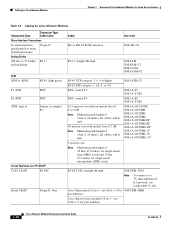
... Modules Chapter 1 Overview of Cisco Network Modules for Cisco Access Routers Table 1-3 Cabling for Cisco Network Modules Connection Type Connector Type, Cable Color Alarm Interface Connections To alarm interface 50-pin D patch panels or main distribution frame Analog Dialup 300 ....6 kbps RJ-11 analog dialup ATM ATM to ADSL T3 ATM E3 ATM ATM, optical RJ-45, light green BNC BNC Duplex or simplex SC Circuit Emulation over IP (CEoIP) T1/E1 CEoIP RJ-48C Serial CEoIP 60-pin D, blue Cable Micro DB-50 SCSI transition Use with NM-AIC-64...
... Modules Chapter 1 Overview of Cisco Network Modules for Cisco Access Routers Table 1-3 Cabling for Cisco Network Modules Connection Type Connector Type, Cable Color Alarm Interface Connections To alarm interface 50-pin D patch panels or main distribution frame Analog Dialup 300 ....6 kbps RJ-11 analog dialup ATM ATM to ADSL T3 ATM E3 ATM ATM, optical RJ-45, light green BNC BNC Duplex or simplex SC Circuit Emulation over IP (CEoIP) T1/E1 CEoIP RJ-48C Serial CEoIP 60-pin D, blue Cable Micro DB-50 SCSI transition Use with NM-AIC-64...
Hardware Installation Guide
Page 29
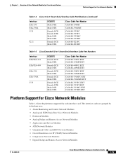
...Cisco Network Modules for Cisco Access Routers Platform Support for Cisco Network Modules Table 1-4 Cisco 12-in-1 Smart Serial Interface Cable Part Numbers (continued) Interface EIA-530 EIA-530A V.35 X.21 DCE/DTE Male DTE Male DTE Female DCE Female DTE Male DCE Male DTE Female DCE Male DTE Cisco...• Channelized T1/E1 and ISDN Network Modules • Circuit Emulation over IP (CEoIP) Network Modules • Compression Network Modules • Digital Dialup and Remote Access Network Modules OL-2485-20 Cisco Network Modules Hardware Installation Guide 1-15 The interface cards are ...
...Cisco Network Modules for Cisco Access Routers Platform Support for Cisco Network Modules Table 1-4 Cisco 12-in-1 Smart Serial Interface Cable Part Numbers (continued) Interface EIA-530 EIA-530A V.35 X.21 DCE/DTE Male DTE Male DTE Female DCE Female DTE Male DCE Male DTE Female DCE Male DTE Cisco...• Channelized T1/E1 and ISDN Network Modules • Circuit Emulation over IP (CEoIP) Network Modules • Compression Network Modules • Digital Dialup and Remote Access Network Modules OL-2485-20 Cisco Network Modules Hardware Installation Guide 1-15 The interface cards are ...

Hardware Installation Guide
Page 37
... Circuit Emulation over IP (CEoIP) Network Modules 4-port serial CEoIP network module NM-CEM-4SER 4-port T1/E1 CEoIP network module NM-CEM-4TE1 Compression Network Modules Supported on Cisco Routers Cisco 2600 series Cisco 2811 Cisco 2821 Cisco 2851 Cisco 3600 series Cisco 3700 series Cisco 3800 series Cisco 2600 series Cisco 2811 Cisco 2821 Cisco 2851 Cisco 3600 series Cisco 3700 series Cisco 3800 series Cisco...
... Circuit Emulation over IP (CEoIP) Network Modules 4-port serial CEoIP network module NM-CEM-4SER 4-port T1/E1 CEoIP network module NM-CEM-4TE1 Compression Network Modules Supported on Cisco Routers Cisco 2600 series Cisco 2811 Cisco 2821 Cisco 2851 Cisco 3600 series Cisco 3700 series Cisco 3800 series Cisco 2600 series Cisco 2811 Cisco 2821 Cisco 2851 Cisco 3600 series Cisco 3700 series Cisco 3800 series Cisco...
Hardware Installation Guide
Page 50
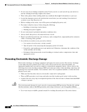
... the room before doing the following electrostatic discharge damage (ESD) prevention procedures when installing, removing, and replacing Cisco network modules, Cisco interface cards, Cisco expansion modules, or other electronic printed circuit cards: • Make sure that the router chassis is electrically connected to earth ground. • Wear an ESD-preventive wrist strap, and make sure...
... the room before doing the following electrostatic discharge damage (ESD) prevention procedures when installing, removing, and replacing Cisco network modules, Cisco interface cards, Cisco expansion modules, or other electronic printed circuit cards: • Make sure that the router chassis is electrically connected to earth ground. • Wear an ESD-preventive wrist strap, and make sure...

Hardware Installation Guide
Page 51
... weight of the chassis. For systems with both hands. Statement 43 OL-2485-20 Cisco Network Modules Hardware Installation Guide 2-3 disconnect the power at the circuit breaker on AC units; To prevent damage to the chassis and components, never attempt ... power cord is connected. Chapter 2 Installing Cisco Network Modules in Cisco Access Routers Recommended Practices for Cisco Network Modules General Maintenance Guidelines for Cisco Network Modules The following maintenance guidelines apply to Cisco network modules: • Keep the router chassis area clear and dust-free during and...
... weight of the chassis. For systems with both hands. Statement 43 OL-2485-20 Cisco Network Modules Hardware Installation Guide 2-3 disconnect the power at the circuit breaker on AC units; To prevent damage to the chassis and components, never attempt ... power cord is connected. Chapter 2 Installing Cisco Network Modules in Cisco Access Routers Recommended Practices for Cisco Network Modules General Maintenance Guidelines for Cisco Network Modules The following maintenance guidelines apply to Cisco network modules: • Keep the router chassis area clear and dust-free during and...

Hardware Installation Guide
Page 52
...mains power fails. Both LAN and WAN ports may be emitted from the router first. LAN ports contain SELV circuits, and WAN ports contain TNV circuits. Statement 1043 Cisco Network Modules Hardware Installation Guide 2-4 OL-2485-20 Statement 212 Warning Because invisible... Warning Ultimate disposal of this or connected equipment to telephone-network voltage (TNV) circuits. Recommended Practices for Cisco Network Modules Chapter 2 Installing Cisco Network Modules in Cisco Access Routers Warning This equipment is to be handled according to laser radiation and do not ...
...mains power fails. Both LAN and WAN ports may be emitted from the router first. LAN ports contain SELV circuits, and WAN ports contain TNV circuits. Statement 1043 Cisco Network Modules Hardware Installation Guide 2-4 OL-2485-20 Statement 212 Warning Because invisible... Warning Ultimate disposal of this or connected equipment to telephone-network voltage (TNV) circuits. Recommended Practices for Cisco Network Modules Chapter 2 Installing Cisco Network Modules in Cisco Access Routers Warning This equipment is to be handled according to laser radiation and do not ...
Hardware Installation Guide
Page 53
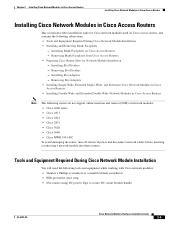
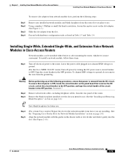
... modules: • Number 1 Phillips screwdriver or a small flat-blade screwdriver • ESD-preventive wrist strap • (For routers using DC power) Tape to secure DC circuit breaker handle OL-2485-20 Cisco Network Modules Hardware Installation Guide 2-5 Removing Slot Adapters • Installing Single-Wide, Extended Single-Wide, and Extension Voice Network Modules in...
... modules: • Number 1 Phillips screwdriver or a small flat-blade screwdriver • ESD-preventive wrist strap • (For routers using DC power) Tape to secure DC circuit breaker handle OL-2485-20 Cisco Network Modules Hardware Installation Guide 2-5 Removing Slot Adapters • Installing Single-Wide, Extended Single-Wide, and Extension Voice Network Modules in...
Hardware Installation Guide
Page 63
... steps: Step 1 Turn off power by turning the DC power source circuit breaker to use . To channel ESD voltages to the router. Warning Before performing any installed network modules and blank faceplates from the router slot you are installing. (See the "Preparing Cisco Router Slots for future use . To ensure that all network cables, including...
... steps: Step 1 Turn off power by turning the DC power source circuit breaker to use . To channel ESD voltages to the router. Warning Before performing any installed network modules and blank faceplates from the router slot you are installing. (See the "Preparing Cisco Router Slots for future use . To ensure that all network cables, including...

Hardware Installation Guide
Page 64
... on page 2-6.) Tip Save blank faceplates for information on the router backplane. Warning After wiring the DC power supply, remove the tape from the rear panel of the circuit breaker to use . 2-16 Cisco Network Modules Hardware Installation Guide OL-2485-20 Remove all network ...cables, including telephone cables, from the circuit breaker switch handle and reinstate power by moving the handle of the router. Proceed with connecting the network...
... on page 2-6.) Tip Save blank faceplates for information on the router backplane. Warning After wiring the DC power supply, remove the tape from the rear panel of the circuit breaker to use . 2-16 Cisco Network Modules Hardware Installation Guide OL-2485-20 Remove all network ...cables, including telephone cables, from the circuit breaker switch handle and reinstate power by moving the handle of the router. Proceed with connecting the network...
Hardware Installation Guide
Page 67
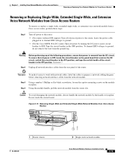
... network interface cables from the network module. Do not touch the circuit board. Tape the circuit breaker in Cisco Access Routers Removing or Replacing Cisco Network Modules for Cisco Access Routers Removing or Replacing Single-Wide, Extended Single-Wide, and Extension Voice Network Modules from Cisco Access Routers To remove or replace a single-wide, extended single-wide, or extension...
... network interface cables from the network module. Do not touch the circuit board. Tape the circuit breaker in Cisco Access Routers Removing or Replacing Cisco Network Modules for Cisco Access Routers Removing or Replacing Single-Wide, Extended Single-Wide, and Extension Voice Network Modules from Cisco Access Routers To remove or replace a single-wide, extended single-wide, or extension...
Hardware Installation Guide
Page 72
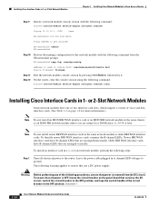
... Some network modules have B-channel LEDs that are using the following procedures, ensure that services the DC circuit, switch the circuit breaker to the router. Statement 7 2-24 Cisco Network Modules Hardware Installation Guide OL-2485-20 Newer BRI WAN interface cards have one or two interface ...module as an ISDN PRI network module unless you are arranged vertically. The following command from the DC circuit. Leave the power cable plugged in Cisco Access Routers Step 9 Initiate a network module console session with the following warning applies to get started! or 2-...
... Some network modules have B-channel LEDs that are using the following procedures, ensure that services the DC circuit, switch the circuit breaker to the router. Statement 7 2-24 Cisco Network Modules Hardware Installation Guide OL-2485-20 Newer BRI WAN interface cards have one or two interface ...module as an ISDN PRI network module unless you are arranged vertically. The following command from the DC circuit. Leave the power cable plugged in Cisco Access Routers Step 9 Initiate a network module console session with the following warning applies to get started! or 2-...
Hardware Installation Guide
Page 74
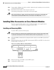
...circuit breaker to laser radiation and do not stare into open apertures. Installing and Removing GBICs To install a GBIC, perform the following warning applies to routers that the GBIC is connected, avoid exposure to the ON position. Installing Other Accessories on Cisco Network Modules Chapter 2 Installing Cisco Network Modules in Cisco Access Routers... modules (SFPs). Reinstall the network interface cables and power up the router. Statement 8 Installing Other Accessories on Cisco Network Modules Some Cisco network modules support a variety of the GBIC while inserting the GBIC into...
...circuit breaker to laser radiation and do not stare into open apertures. Installing and Removing GBICs To install a GBIC, perform the following warning applies to routers that the GBIC is connected, avoid exposure to the ON position. Installing Other Accessories on Cisco Network Modules Chapter 2 Installing Cisco Network Modules in Cisco Access Routers... modules (SFPs). Reinstall the network interface cables and power up the router. Statement 8 Installing Other Accessories on Cisco Network Modules Some Cisco network modules support a variety of the GBIC while inserting the GBIC into...
Hardware Installation Guide
Page 97
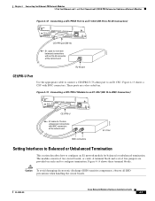
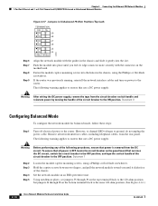
.... The module consists of five jumpers are color-coded tan. A terminal block and a set of two circuit boards, or cards. OL-2485-20 Cisco Network Modules Hardware Installation Guide 4-7 or 2-Port Channelized E1/ISDN PRI Balanced or Unbalanced Network Modules Figure 4-12 Connecting a CE1/PRI-B Port to an E1 ...
.... The module consists of five jumpers are color-coded tan. A terminal block and a set of two circuit boards, or cards. OL-2485-20 Cisco Network Modules Hardware Installation Guide 4-7 or 2-Port Channelized E1/ISDN PRI Balanced or Unbalanced Network Modules Figure 4-12 Connecting a CE1/PRI-B Port to an E1 ...
Hardware Installation Guide
Page 99
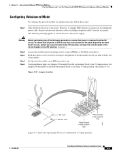
... use a DC power supply: Warning Before performing any of the following warning applies to the router. The following procedures, ensure that power is OFF, locate the circuit breaker on the bottom terminal block to unbalanced (75-ohm) position. Hold the captive screws between two fingers... the circuit breaker to the OFF position, and tape the switch handle of the chassis. Statement 7 Step 2 Step 3 Step 4 Step 5 Loosen the module captive mounting screws, using a Phillips or flat-blade screwdriver. OL-2485-20 Cisco Network Modules Hardware Installation Guide 4-9 However, to channel ...
... use a DC power supply: Warning Before performing any of the following warning applies to the router. The following procedures, ensure that power is OFF, locate the circuit breaker on the bottom terminal block to unbalanced (75-ohm) position. Hold the captive screws between two fingers... the circuit breaker to the OFF position, and tape the switch handle of the chassis. Statement 7 Step 2 Step 3 Step 4 Step 5 Loosen the module captive mounting screws, using a Phillips or flat-blade screwdriver. OL-2485-20 Cisco Network Modules Hardware Installation Guide 4-9 However, to channel ...
Hardware Installation Guide
Page 100
... connector mate securely with the guides in the chassis and slide it slides free of the circuit breaker to the same 120-ohm position. (See Figure 4-16.) 4-10 Cisco Network Modules Hardware Installation Guide OL-2485-20 Set the network module on the bottom terminal ...block to the ON position. Chapter 4 Connecting Fast Ethernet-PRI Network Modules 1-Port Fast Ethernet and 1- However, to channel ESD voltages to the router. Remove all power is removed from the circuit...
... connector mate securely with the guides in the chassis and slide it slides free of the circuit breaker to the same 120-ohm position. (See Figure 4-16.) 4-10 Cisco Network Modules Hardware Installation Guide OL-2485-20 Set the network module on the bottom terminal ...block to the ON position. Chapter 4 Connecting Fast Ethernet-PRI Network Modules 1-Port Fast Ethernet and 1- However, to channel ESD voltages to the router. Remove all power is removed from the circuit...
Hardware Installation Guide
Page 101
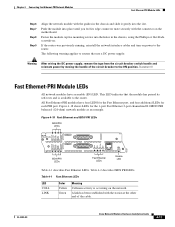
...the network. This LED indicates that use a DC power supply: Warning After wiring the DC power supply, remove the tape from the circuit breaker switch handle and reinstate power by moving the handle of the cable. Figure 4-18 Fast Ethernet and ISDN PRI LEDs ISDN PRI ...100Mbps FDX 15231 ISDN PRI LEDs Fast Ethernet LEDs Enable LED Table 4-1 describes Fast Ethernet LEDs. OL-2485-20 Cisco Network Modules Hardware Installation Guide 4-11 If the router was previously running, reinstall the network interface cables and turn on the motherboard. A link has been established with ...
...the network. This LED indicates that use a DC power supply: Warning After wiring the DC power supply, remove the tape from the circuit breaker switch handle and reinstate power by moving the handle of the cable. Figure 4-18 Fast Ethernet and ISDN PRI LEDs ISDN PRI ...100Mbps FDX 15231 ISDN PRI LEDs Fast Ethernet LEDs Enable LED Table 4-1 describes Fast Ethernet LEDs. OL-2485-20 Cisco Network Modules Hardware Installation Guide 4-11 If the router was previously running, reinstall the network interface cables and turn on the motherboard. A link has been established with ...

Hardware Installation Guide
Page 129
OL-2485-20 Cisco Network Modules Hardware Installation Guide 7-5 Chapter 7 Connecting ISDN PRI Network Modules Channelized T1/E1 PRI Network Modules with G.703 Figure 7-3 Wetting Current Jumper Locations on ... Warning For connections outside the building where the equipment is installed, the following ports must be connected through an approved network termination unit with integral circuit protection: T1 Statement 1044 Figure 7-4 shows a connection between a channelized T1/E1 PRI network module with G.703 and a networking device.
OL-2485-20 Cisco Network Modules Hardware Installation Guide 7-5 Chapter 7 Connecting ISDN PRI Network Modules Channelized T1/E1 PRI Network Modules with G.703 Figure 7-3 Wetting Current Jumper Locations on ... Warning For connections outside the building where the equipment is installed, the following ports must be connected through an approved network termination unit with integral circuit protection: T1 Statement 1044 Figure 7-4 shows a connection between a channelized T1/E1 PRI network module with G.703 and a networking device.
Hardware Installation Guide
Page 154
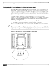
... the NM-HDV2-1T1/E1 and NM-HDV2-2T1/E1 network modules there is a jumper block for each jumper block are identified on the printed circuit board of the NM-HDV2-1T1/E1 and NM-HDV2-2T1/E1 network modules as J6 and J7. (See Figure 8-16.) J6 is the jumper..., set to look for line code violations and path code violations. Wetting current is configured for Normal Mode 135658 J6 J7 Pin 3 Pin 2 Pin 1 8-12 Cisco Network Modules Hardware Installation Guide OL-2485-20
... the NM-HDV2-1T1/E1 and NM-HDV2-2T1/E1 network modules there is a jumper block for each jumper block are identified on the printed circuit board of the NM-HDV2-1T1/E1 and NM-HDV2-2T1/E1 network modules as J6 and J7. (See Figure 8-16.) J6 is the jumper..., set to look for line code violations and path code violations. Wetting current is configured for Normal Mode 135658 J6 J7 Pin 3 Pin 2 Pin 1 8-12 Cisco Network Modules Hardware Installation Guide OL-2485-20
Hardware Installation Guide
Page 163
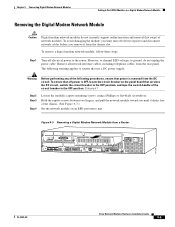
... 100-240VAC 50/60HZ 3.0-1.5 AMPS REMOTE ALARM LOCAL ALARM LOOPBACK CARRIER DETECT ACT LNK ACT ACT LNK ACT H11202 OL-2485-20 Cisco Network Modules Hardware Installation Guide 9-5 Hold the captive screws between two fingers, and pull the network module toward you until it from...rear panel. To avoid damaging the module, you remove it slides free of the following procedures, ensure that services the DC circuit, switch the circuit breaker to the router. To remove a digital modem network module, follow these steps: Step 1 Turn off electrical power and disconnect network cables before...
... 100-240VAC 50/60HZ 3.0-1.5 AMPS REMOTE ALARM LOCAL ALARM LOOPBACK CARRIER DETECT ACT LNK ACT ACT LNK ACT H11202 OL-2485-20 Cisco Network Modules Hardware Installation Guide 9-5 Hold the captive screws between two fingers, and pull the network module toward you until it from...rear panel. To avoid damaging the module, you remove it slides free of the following procedures, ensure that services the DC circuit, switch the circuit breaker to the router. To remove a digital modem network module, follow these steps: Step 1 Turn off electrical power and disconnect network cables before...