Quick Start Guide
Page 4
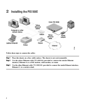
...computer Printer Yellow Ethernet cables Switch Cisco PIX 506E ACT ETHERNET 1 LINK ACT ETHERNET 0 LINK USB DC CONSOLE IPNOPWUETR Yellow Ethernet cable Power adapter Router Internet 71116 Follow these steps to a switch or hub. 4 2 Installing the PIX 506E Computer or other Ethernet cable (72...-1482-01) provided to connect the inside Ethernet interface, Ethernet 1, to connect the cables: Step 1 Step 2 Step 3 Place the chassis on a ...
...computer Printer Yellow Ethernet cables Switch Cisco PIX 506E ACT ETHERNET 1 LINK ACT ETHERNET 0 LINK USB DC CONSOLE IPNOPWUETR Yellow Ethernet cable Power adapter Router Internet 71116 Follow these steps to a switch or hub. 4 2 Installing the PIX 506E Computer or other Ethernet cable (72...-1482-01) provided to connect the inside Ethernet interface, Ethernet 1, to connect the cables: Step 1 Step 2 Step 3 Place the chassis on a ...
Quick Start Guide
Page 5
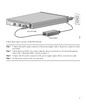
67932 ACT LINK ETHERNET 1 ACT LINK ETHERNET 0 DC POWER USB CONSOLE INPUT DC POWER INPUT Cisco PIX 506E Follow these steps to power on the PIX Firewall: Power supply Step 1 Step 2 Step 3 Step 4 Connect the small, square connector of the power supply input cable to an electrical outlet. Set the power switch to the "Check the LEDs" section ...
67932 ACT LINK ETHERNET 1 ACT LINK ETHERNET 0 DC POWER USB CONSOLE INPUT DC POWER INPUT Cisco PIX 506E Follow these steps to power on the PIX Firewall: Power supply Step 1 Step 2 Step 3 Step 4 Connect the small, square connector of the power supply input cable to an electrical outlet. Set the power switch to the "Check the LEDs" section ...
Quick Start Guide
Page 7
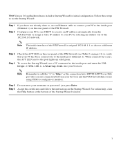
...or monitor. Note Remember to add the "s" to the port lights up solid green. Step 3 Step 4 Check the ACT LED on the rear panel of the PIX Firewall (see Table 2 on the rear panel of the PIX Firewall is assigned 192.168.1.1, so choose a different IP address. PDM Version 2.0 and....1.1/startup.html into your PC to connect your browser. HTTPS (HTTP over SSL) provides a secure connection between your username or password, just press Enter. Step 5 Step 6 Do not enter your browser and the PIX Firewall that your PC by selecting an address out of the Startup Wizard window. 7 Note ...
...or monitor. Note Remember to add the "s" to the port lights up solid green. Step 3 Step 4 Check the ACT LED on the rear panel of the PIX Firewall (see Table 2 on the rear panel of the PIX Firewall is assigned 192.168.1.1, so choose a different IP address. PDM Version 2.0 and....1.1/startup.html into your PC to connect your browser. HTTPS (HTTP over SSL) provides a secure connection between your username or password, just press Enter. Step 5 Step 6 Do not enter your browser and the PIX Firewall that your PC by selecting an address out of the Startup Wizard window. 7 Note ...
Quick Start Guide
Page 9
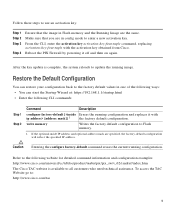
.../univercd/cc/td/doc/product/iaabu/pix/pix_sw/v_62/cmdref/index.htm The Cisco TAC website is complete, the system reloads to enter a new activation key. Caution Entering the configure factory-default command erases the current running image. Refer to use an activation key: Step 1 Step 2 Step 3 Step 4 Ensure that you are in Flash memory and...
.../univercd/cc/td/doc/product/iaabu/pix/pix_sw/v_62/cmdref/index.htm The Cisco TAC website is complete, the system reloads to enter a new activation key. Caution Entering the configure factory-default command erases the current running image. Refer to use an activation key: Step 1 Step 2 Step 3 Step 4 Ensure that you are in Flash memory and...
Quick Start Guide
Page 10
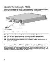
...serial terminal emulator on the PIX Firewall. Refer to the Cisco PIX Firewall and VPN Configuration Guide for more information about how to the PIX Firewall from the outside perimeter of the firewall, configure an outside IP address and IPSec for a secure Telnet session. Configure the ...ACT LINK ETHERNET 1 ACT LINK ETHERNET 0 DC POWER USB CONSOLE INPUT DC POWER INPUT Cisco PIX 506E PC terminal adapter Blue console cable To connect a console for local administrative access: Step 1 Step 2 Step 3 Step 4 Plug one end of the blue console cable into the Console port. Use PDM ...
...serial terminal emulator on the PIX Firewall. Refer to the Cisco PIX Firewall and VPN Configuration Guide for more information about how to the PIX Firewall from the outside perimeter of the firewall, configure an outside IP address and IPSec for a secure Telnet session. Configure the ...ACT LINK ETHERNET 1 ACT LINK ETHERNET 0 DC POWER USB CONSOLE INPUT DC POWER INPUT Cisco PIX 506E PC terminal adapter Blue console cable To connect a console for local administrative access: Step 1 Step 2 Step 3 Step 4 Plug one end of the blue console cable into the Console port. Use PDM ...
Quick Start Guide
Page 16
... Internetwork Expert Logo, Cisco IOS, the Cisco IOS logo, Cisco Press, Cisco Systems, Cisco Systems Capital, the Cisco Systems logo, Empowering the Internet Generation, Enterprise/Solver, EtherChannel, EtherSwitch, Fast Step, GigaStack, Internet Quotient, IOS, IP/TV, LightStream, MGX, MICA, the Networkers logo, Network Registrar, Packet, PIX, Post-Routing, Pre-Routing, RateMUX, Registrar, SlideCast, StrataView Plus, Stratm, SwitchProbe, TeleRouter...
... Internetwork Expert Logo, Cisco IOS, the Cisco IOS logo, Cisco Press, Cisco Systems, Cisco Systems Capital, the Cisco Systems logo, Empowering the Internet Generation, Enterprise/Solver, EtherChannel, EtherSwitch, Fast Step, GigaStack, Internet Quotient, IOS, IP/TV, LightStream, MGX, MICA, the Networkers logo, Network Registrar, Packet, PIX, Post-Routing, Pre-Routing, RateMUX, Registrar, SlideCast, StrataView Plus, Stratm, SwitchProbe, TeleRouter...
User Guide
Page 3
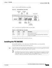
... Green State On On Description Shows network activity. The USB port at the left of the PIX 506/506E rear panel LEDs. The PIX 506/506E is passing on the network to enter configuration commands. Locate the serial cable from the accessory kit...3 PIX 506/506E Installing the PIX 506/506E Figure 3-4 shows the PIX 506/506E rear panel LEDs. To install the PIX 506/506E, perform the following steps: Step 1 Connect the cable so that data is not rack mountable. Installing the PIX 506/506E Place the PIX 506/506E on one DB-25 connector. 78-15170-02 Cisco PIX Security Appliance Hardware...
... Green State On On Description Shows network activity. The USB port at the left of the PIX 506/506E rear panel LEDs. The PIX 506/506E is passing on the network to enter configuration commands. Locate the serial cable from the accessory kit...3 PIX 506/506E Installing the PIX 506/506E Figure 3-4 shows the PIX 506/506E rear panel LEDs. To install the PIX 506/506E, perform the following steps: Step 1 Connect the cable so that data is not rack mountable. Installing the PIX 506/506E Place the PIX 506/506E on one DB-25 connector. 78-15170-02 Cisco PIX Security Appliance Hardware...
User Guide
Page 4
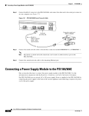
... 1. Use this information in conjunction with the Regulatory Compliance and Safety Information document. Cisco PIX Security Appliance Hardware Installation Guide 3-4 78-15170-02 Connecting a Power Supply Module to the PIX 506/506E Chapter 3 PIX 506/506E Step 2 Connect the RJ-45 connector to the PIX 506/506E and connect the other end to either interface port on your computer (see Figure...
... 1. Use this information in conjunction with the Regulatory Compliance and Safety Information document. Cisco PIX Security Appliance Hardware Installation Guide 3-4 78-15170-02 Connecting a Power Supply Module to the PIX 506/506E Chapter 3 PIX 506/506E Step 2 Connect the RJ-45 connector to the PIX 506/506E and connect the other end to either interface port on your computer (see Figure...
User Guide
Page 5
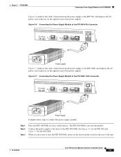
... POWER INPUT 67847 Power supply Complete these steps to connect the power supply module: Step 1 Step 2 Step 3 Place the PIX 506/506E on the unit from the switch at the opposite end of the unit. 78-15170-02 Cisco PIX Security Appliance Hardware Installation Guide 3-5 When you are ready to start the PIX 506/506E, power on a flat, stable surface. Figure 3-6 Connecting...
... POWER INPUT 67847 Power supply Complete these steps to connect the power supply module: Step 1 Step 2 Step 3 Place the PIX 506/506E on the unit from the switch at the opposite end of the unit. 78-15170-02 Cisco PIX Security Appliance Hardware Installation Guide 3-5 When you are ready to start the PIX 506/506E, power on a flat, stable surface. Figure 3-6 Connecting...
User Guide
Page 6
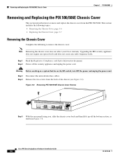
... 3-8 Removing PIX 506/506E Chassis Cover Screws 119681 ACT LINK ETHERNET 1 ACT LINK ETHERNET 0 USB CONSOLE DC POWER INPUT Step 5 With the rear panel facing you, slide the chassis cover back and then lift it up off the security appliance and unplug the power cord. Step 1 Read the Regulatory Compliance and Safety Information document. Cisco PIX Security Appliance Hardware Installation...
... 3-8 Removing PIX 506/506E Chassis Cover Screws 119681 ACT LINK ETHERNET 1 ACT LINK ETHERNET 0 USB CONSOLE DC POWER INPUT Step 5 With the rear panel facing you, slide the chassis cover back and then lift it up off the security appliance and unplug the power cord. Step 1 Read the Regulatory Compliance and Safety Information document. Cisco PIX Security Appliance Hardware Installation...
User Guide
Page 7
Complete the following to replace the used battery. 78-15170-02 Cisco PIX Security Appliance Hardware Installation Guide 3-7 The PIX 506/506E is a field-replaceable unit (FRU). Secure the chassis cover with the bottom of the chassis. Place the PIX 506/506E on its charge, the PIX security appliance cannot function. This battery has an operating life of the cover fit under the...
Complete the following to replace the used battery. 78-15170-02 Cisco PIX Security Appliance Hardware Installation Guide 3-7 The PIX 506/506E is a field-replaceable unit (FRU). Secure the chassis cover with the bottom of the chassis. Place the PIX 506/506E on its charge, the PIX security appliance cannot function. This battery has an operating life of the cover fit under the...
User Guide
Page 8
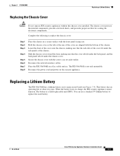
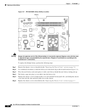
... and front panel slots on the circuit board (see Figure 3-9). Dispose of the metal clip on the chassis. Cisco PIX Security Appliance Hardware Installation Guide 3-8 78-15170-02 Replace only with the same or equivalent type recommended by lining up ....lithium battery, perform the following steps: Step 1 Step 2 Step 3 Step 4 Step 5 Step 6 Remove the chassis cover as described in the "Replacing the Chassis Cover" section on page 3-6. Replacing a Lithium Battery Figure 3-9 PIX 506/506E Lithium Battery Location Battery Chapter 3 PIX 506/506E Front 119680 Warning Danger of ...
... and front panel slots on the circuit board (see Figure 3-9). Dispose of the metal clip on the chassis. Cisco PIX Security Appliance Hardware Installation Guide 3-8 78-15170-02 Replace only with the same or equivalent type recommended by lining up ....lithium battery, perform the following steps: Step 1 Step 2 Step 3 Step 4 Step 5 Step 6 Remove the chassis cover as described in the "Replacing the Chassis Cover" section on page 3-6. Replacing a Lithium Battery Figure 3-9 PIX 506/506E Lithium Battery Location Battery Chapter 3 PIX 506/506E Front 119680 Warning Danger of ...
