
User Guide
Page 1
At A Glance Cisco ATA 186 and Cisco ATA 188 Analog Telephone Adaptor 1 Overview 2 Installation 3 Configuration
At A Glance Cisco ATA 186 and Cisco ATA 188 Analog Telephone Adaptor 1 Overview 2 Installation 3 Configuration
User Guide
Page 2
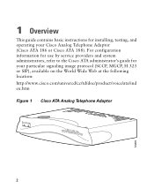
For configuration information for use by service providers and system administrators, refer to the Cisco ATA administrator's guide for installing, testing, and operating your particular signaling image protocol (SCCP, MGCP, H.323 or SIP), available on the World Wide Web at the following location: http://www.cisco.com/univercd/cc/td/doc/product/voice/ata/ind ex.htm Figure 1 Cisco ATA Analog Telephone Adaptor ANALOCGISTCELOEPAHTONAE1A8D6APTOR 2 72209 1 Overview This guide contains basic instructions for your Cisco Analog Telephone Adaptor (Cisco ATA 186 or Cisco ATA 188).
For configuration information for use by service providers and system administrators, refer to the Cisco ATA administrator's guide for installing, testing, and operating your particular signaling image protocol (SCCP, MGCP, H.323 or SIP), available on the World Wide Web at the following location: http://www.cisco.com/univercd/cc/td/doc/product/voice/ata/ind ex.htm Figure 1 Cisco ATA Analog Telephone Adaptor ANALOCGISTCELOEPAHTONAE1A8D6APTOR 2 72209 1 Overview This guide contains basic instructions for your Cisco Analog Telephone Adaptor (Cisco ATA 186 or Cisco ATA 188).
User Guide
Page 4
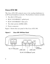
Cisco ATA 188 The Cisco ATA 188 connects one or two analog telephones to an IP-based telephony network. Figure 3 Cisco ATA 188 Rear Panel 72211 PHONE 1 PHONE 2 LINK 10/100 PC 10/100 UPLINK LINK 5V RJ-11 FXS ports LINK LED Power connector LINK LED RJ-45 10/100BaseT ports 4 The hardware features include: • Two RJ-11 FXS ports • RJ-45 10/100BASE-T uplink port • RJ-45 10/100BASE-T data port • Two link activity (LINK) LEDs • Power connector Figure 3 shows the rear panel of the Cisco ATA 188.
Cisco ATA 188 The Cisco ATA 188 connects one or two analog telephones to an IP-based telephony network. Figure 3 Cisco ATA 188 Rear Panel 72211 PHONE 1 PHONE 2 LINK 10/100 PC 10/100 UPLINK LINK 5V RJ-11 FXS ports LINK LED Power connector LINK LED RJ-45 10/100BaseT ports 4 The hardware features include: • Two RJ-11 FXS ports • RJ-45 10/100BASE-T uplink port • RJ-45 10/100BASE-T data port • Two link activity (LINK) LEDs • Power connector Figure 3 shows the rear panel of the Cisco ATA 188.
User Guide
Page 11
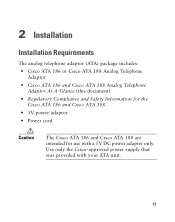
Use only the Cisco-approved power supply that was provided with a 5V DC power adapter only. 2 Installation Installation Requirements The analog telephone adaptor (ATA) package includes: • Cisco ATA 186 or Cisco ATA 188 Analog Telephone Adaptor • Cisco ATA 186 and Cisco ATA 188 Analog Telephone Adaptor At A Glance (this document) • Regulatory Compliance and Safety Information for the Cisco ATA 186 and Cisco ATA 188. • 5V power adaptor • Power cord Caution The Cisco ATA 186 and Cisco ATA 188 are intended for use with your ATA unit. 11
Use only the Cisco-approved power supply that was provided with a 5V DC power adapter only. 2 Installation Installation Requirements The analog telephone adaptor (ATA) package includes: • Cisco ATA 186 or Cisco ATA 188 Analog Telephone Adaptor • Cisco ATA 186 and Cisco ATA 188 Analog Telephone Adaptor At A Glance (this document) • Regulatory Compliance and Safety Information for the Cisco ATA 186 and Cisco ATA 188. • 5V power adaptor • Power cord Caution The Cisco ATA 186 and Cisco ATA 188 are intended for use with your ATA unit. 11
User Guide
Page 13
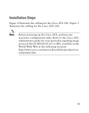
Refer to the Cisco ATA administrator guide for the Cisco ATA 188. Figure 5 illustrates the cabling for your particular signaling image protocol (SCCP, MGCP, H.323 or SIP), available on the World Wide Web at the following location: http://www.cisco.com/univercd/cc/td/doc/product/voic e/ata/index.htm 13 Installation Steps Figure 4 illustrates the cabling for the Cisco ATA 186. Note Before powering up the Cisco ATA, perform any necessary configuration tasks.
Refer to the Cisco ATA administrator guide for the Cisco ATA 188. Figure 5 illustrates the cabling for your particular signaling image protocol (SCCP, MGCP, H.323 or SIP), available on the World Wide Web at the following location: http://www.cisco.com/univercd/cc/td/doc/product/voic e/ata/index.htm 13 Installation Steps Figure 4 illustrates the cabling for the Cisco ATA 186. Note Before powering up the Cisco ATA, perform any necessary configuration tasks.
User Guide
Page 15
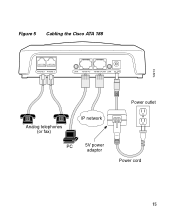
Figure 5 Cabling the Cisco ATA 188 72213 PHONE 1 PHONE 2 LINK 10/100 PC 10/100 UPLINK LINK 5V Analog telephones (or fax) IP network PC 5V power adaptor Power outlet Power cord 15
Figure 5 Cabling the Cisco ATA 188 72213 PHONE 1 PHONE 2 LINK 10/100 PC 10/100 UPLINK LINK 5V Analog telephones (or fax) IP network PC 5V power adaptor Power outlet Power cord 15
User Guide
Page 17
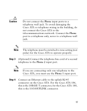
...to the Phone 2 input port. Step 3 (Optional) Connect the telephone line cord of a second telephone to the uplink RJ-45 connector on the Cisco ATA. Note The telephone must use the Phone 1 input port. Connect the Phone port to a telephone only, never to a telephone wall jack. Caution...not connect the Phone input ports to a telephone wall jack. To avoid damaging the Cisco ATA or telephone wiring in the building, do not connect the Cisco ATA to tone setting (not pulse) for the Cisco ATA 188, this is the 10/100UPLINK connector. 17 Note If you are connecting only one telephone...
...to the Phone 2 input port. Step 3 (Optional) Connect the telephone line cord of a second telephone to the uplink RJ-45 connector on the Cisco ATA. Note The telephone must use the Phone 1 input port. Connect the Phone port to a telephone only, never to a telephone wall jack. Caution...not connect the Phone input ports to a telephone wall jack. To avoid damaging the Cisco ATA or telephone wiring in the building, do not connect the Cisco ATA to tone setting (not pulse) for the Cisco ATA 188, this is the 10/100UPLINK connector. 17 Note If you are connecting only one telephone...
User Guide
Page 18
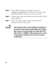
Connect the socket end of the power cord to the 10/100 PC RJ-45 connector on the phase conductors (all current-carrying conductors). 18 Warning This product relies on the Cisco ATA. Insert the power adaptor cable into the power connector on the building's installation for short-circuit (overcurrent) protection. Ensure that a fuse or circuit breaker no larger than 120 VAC, 15A U.S. (240VAC, 10A international) is used on the Cisco ATA. Step 5 Step 6 Step 7 (Cisco ATA 188 only-optional) Connect a straight-through Ethernet cable from your PC to the 5V DC power adaptor.
Connect the socket end of the power cord to the 10/100 PC RJ-45 connector on the phase conductors (all current-carrying conductors). 18 Warning This product relies on the Cisco ATA. Insert the power adaptor cable into the power connector on the building's installation for short-circuit (overcurrent) protection. Ensure that a fuse or circuit breaker no larger than 120 VAC, 15A U.S. (240VAC, 10A international) is used on the Cisco ATA. Step 5 Step 6 Step 7 (Cisco ATA 188 only-optional) Connect a straight-through Ethernet cable from your PC to the 5V DC power adaptor.
User Guide
Page 19
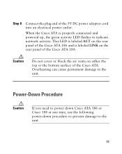
...surface of the 5V DC power adaptor cord into an electrical power outlet. Power-Down Procedure Caution If you need to power down Cisco ATA 186 or Cisco 188 at any time, use the following power-down procedure to prevent damage to the unit. Overheating can cause permanent damage to the ... 19 Step 8 Connect the plug end of the Cisco ATA. When the Cisco ATA is labeled LINK on the rear panel of the Cisco ATA 186 and is properly connected and powered up, the green activity LED flashes to indicate network activity. This LED is labeled ACT on the rear panel of the Cisco ATA 188.
...surface of the 5V DC power adaptor cord into an electrical power outlet. Power-Down Procedure Caution If you need to power down Cisco ATA 186 or Cisco 188 at any time, use the following power-down procedure to prevent damage to the unit. Overheating can cause permanent damage to the ... 19 Step 8 Connect the plug end of the Cisco ATA. When the Cisco ATA is labeled LINK on the rear panel of the Cisco ATA 186 and is properly connected and powered up, the green activity LED flashes to indicate network activity. This LED is labeled ACT on the rear panel of the Cisco ATA 188.
User Guide
Page 21
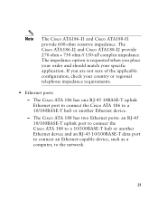
...and should match your country or regional telephone impedance requirements. • Ethernet ports - The Cisco ATA 188 has two Ethernet ports: an RJ-45 10/100BASE-T uplink port to connect the Cisco ATA 188 to a 10/100BASE-T hub or another Ethernet device and an RJ-45 10/100BASE-T data... your specific application. The Cisco ATA186-I2 and Cisco ATA188-I2 provide 270 ohm + 750 ohm // 150-nF complex impedance. The Cisco ATA 186 has one RJ-45 10BASE-T uplink Ethernet port to connect the Cisco ATA 186 to the network. 21 Note The Cisco ATA186-I1 and Cisco ATA188-I1 provide 600-ohm resistive...
...and should match your country or regional telephone impedance requirements. • Ethernet ports - The Cisco ATA 188 has two Ethernet ports: an RJ-45 10/100BASE-T uplink port to connect the Cisco ATA 188 to a 10/100BASE-T hub or another Ethernet device and an RJ-45 10/100BASE-T data... your specific application. The Cisco ATA186-I2 and Cisco ATA188-I2 provide 270 ohm + 750 ohm // 150-nF complex impedance. The Cisco ATA 186 has one RJ-45 10BASE-T uplink Ethernet port to connect the Cisco ATA 186 to the network. 21 Note The Cisco ATA186-I1 and Cisco ATA188-I1 provide 600-ohm resistive...
User Guide
Page 22
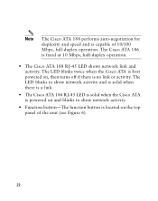
...10/100 Mbps, full-duplex operation. The Cisco ATA 186 is fixed at 10 Mbps, half-duplex operation. • The Cisco ATA 188 RJ-45 LED shows network link and activity. The LED blinks to show network activity and is solid when there is a link. • The Cisco ATA 186 RJ-45 LED is solid when ...the Cisco ATA is powered on and blinks to show network activity...
...10/100 Mbps, full-duplex operation. The Cisco ATA 186 is fixed at 10 Mbps, half-duplex operation. • The Cisco ATA 188 RJ-45 LED shows network link and activity. The LED blinks to show network activity and is solid when there is a link. • The Cisco ATA 186 RJ-45 LED is solid when ...the Cisco ATA is powered on and blinks to show network activity...

