
Hardware Installation Guide
Page 2
... Cisco Systems, Inc. CCVP, the Cisco Logo, and the Cisco Square Bridge logo are designed to operate the product. Cisco Aironet 1100 Series Access Point Hardware Installation Guide © 2006 Cisco Systems, Inc. THE SPECIFICATIONS AND INFORMATION REGARDING THE PRODUCTS IN THIS MANUAL ARE SUBJECT TO CHANGE WITHOUT NOTICE. These specifications are trademarks of Cisco Systems, Inc. The following information is for a Class A digital device, pursuant to part...
... Cisco Systems, Inc. CCVP, the Cisco Logo, and the Cisco Square Bridge logo are designed to operate the product. Cisco Aironet 1100 Series Access Point Hardware Installation Guide © 2006 Cisco Systems, Inc. THE SPECIFICATIONS AND INFORMATION REGARDING THE PRODUCTS IN THIS MANUAL ARE SUBJECT TO CHANGE WITHOUT NOTICE. These specifications are trademarks of Cisco Systems, Inc. The following information is for a Class A digital device, pursuant to part...
Hardware Installation Guide
Page 8
...Means the following will help you supply values are in boldface text. • Arguments for basic problems with the lightweight access point. Chapter 4, "2.4-GHz Radio Upgrade for Autonomous Access Points," provides upgrade instructions for changing the 2.4 GHz radio Chapter 5, "Troubleshooting Autonomous Access Points," provides troubleshooting procedures for which you solve a problem. Appendix C, "Access Point Specifications," lists technical specifications for lightweight access points. Conventions This publication uses these conventions to access the document that appear in angle...
...Means the following will help you supply values are in boldface text. • Arguments for basic problems with the lightweight access point. Chapter 4, "2.4-GHz Radio Upgrade for Autonomous Access Points," provides upgrade instructions for changing the 2.4 GHz radio Chapter 5, "Troubleshooting Autonomous Access Points," provides troubleshooting procedures for which you solve a problem. Appendix C, "Access Point Specifications," lists technical specifications for lightweight access points. Conventions This publication uses these conventions to access the document that appear in angle...

Hardware Installation Guide
Page 16
... Cisco Aironet 1100 Series Access Point Hardware Installation Guide xvi OL-4309-07 Updated monthly, this online publication is organized by Cisco for many Cisco products that includes brief product overviews, key features, sample part numbers, and abbreviated technical specifications for engineering professionals involved in Cisco Documentation" is a quarterly journal published by product category to direct you quickly to this URL: http://www.cisco.com/discuss/networking • "What's New...
... Cisco Aironet 1100 Series Access Point Hardware Installation Guide xvi OL-4309-07 Updated monthly, this online publication is organized by Cisco for many Cisco products that includes brief product overviews, key features, sample part numbers, and abbreviated technical specifications for engineering professionals involved in Cisco Documentation" is a quarterly journal published by product category to direct you quickly to this URL: http://www.cisco.com/discuss/networking • "What's New...
Hardware Installation Guide
Page 17
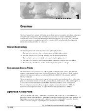
... bridge. The autonomous access points can configure and monitor the access point using the Lightweight Access Point Protocol (LWAPP). The lightweight access points operate in autonomous and lightweight configurations. OL-4309-07 Cisco Aironet 1100 Series Access Point Hardware Installation Guide 1-1 You can support standalone network configurations with all configuration settings maintained within the access points. The 1100 series is available in conjunction with a Cisco wireless LAN controller with all configuration information maintained within radio range of an access point...
... bridge. The autonomous access points can configure and monitor the access point using the Lightweight Access Point Protocol (LWAPP). The lightweight access points operate in autonomous and lightweight configurations. OL-4309-07 Cisco Aironet 1100 Series Access Point Hardware Installation Guide 1-1 You can support standalone network configurations with all configuration settings maintained within the access points. The 1100 series is available in conjunction with a Cisco wireless LAN controller with all configuration information maintained within radio range of an access point...

Hardware Installation Guide
Page 18
..., all wireless traffic is joined, the access point downloads its software if the versions on the following topics: • Hardware Features, page 1-3 • Network Examples with Autonomous Access Points, page 1-5 • Network Example with Lightweight Access Points, page 1-9 Cisco Aironet 1100 Series Access Point Hardware Installation Guide 1-2 OL-4309-07 In an LWAPP environment, a lightweight access point discovers a controller by means of a secure key distribution, using LWAPP discovery mechanisms and then sends it to autonomous mode...
..., all wireless traffic is joined, the access point downloads its software if the versions on the following topics: • Hardware Features, page 1-3 • Network Examples with Autonomous Access Points, page 1-5 • Network Example with Lightweight Access Points, page 1-9 Cisco Aironet 1100 Series Access Point Hardware Installation Guide 1-2 OL-4309-07 In an LWAPP environment, a lightweight access point discovers a controller by means of a secure key distribution, using LWAPP discovery mechanisms and then sends it to autonomous mode...
Hardware Installation Guide
Page 19
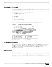
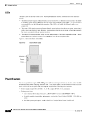
... the Ethernet cable from a power injector, switch, or power patch panel. Ethernet Port The auto-sensing Ethernet port accepts an RJ-45 connector, linking the access point to Appendix C, "Access Point Specifications," for a list of access point specifications. The access point can perform a field upgrade to the mini-PCI radio and antennas to support new radio technologies, such as the 2.4-GHz IEEE 802.11g-compliant radio. Key hardware features of the 1100 series access point include: • Single Radio Operation, page 1-3 • Ethernet Port, page 1-3 • LEDs...
... the Ethernet cable from a power injector, switch, or power patch panel. Ethernet Port The auto-sensing Ethernet port accepts an RJ-45 connector, linking the access point to Appendix C, "Access Point Specifications," for a list of access point specifications. The access point can perform a field upgrade to the mini-PCI radio and antennas to support new radio technologies, such as the 2.4-GHz IEEE 802.11g-compliant radio. Key hardware features of the 1100 series access point include: • Single Radio Operation, page 1-3 • Ethernet Port, page 1-3 • LEDs...
Hardware Installation Guide
Page 20
... the access point report Ethernet activity, association status, and radio activity. • The Ethernet LED signals Ethernet traffic on the wired LAN, or Ethernet infrastructure. Figure 1-2 shows the three status LEDs. Steady green indicates that the access point is operating normally but it blinks green whenever a packet is received or transmitted over the radio interface. The light is normally off when the Ethernet cable is not associated with at least one wireless client. Cisco Aironet Power Injector (Cisco AIR...
... the access point report Ethernet activity, association status, and radio activity. • The Ethernet LED signals Ethernet traffic on the wired LAN, or Ethernet infrastructure. Figure 1-2 shows the three status LEDs. Steady green indicates that the access point is operating normally but it blinks green whenever a packet is received or transmitted over the radio interface. The light is normally off when the Ethernet cable is not associated with at least one wireless client. Cisco Aironet Power Injector (Cisco AIR...

Hardware Installation Guide
Page 21
... air space; The autonomous 1100 series access point supports these operating wireless modes: • Root access point-Connected to a wired LAN and supports wireless clients. • Repeater access point-Not connected to a wired LAN, associates to a root access point, and supports wireless clients • Workgroup bridge-Not connected to a wired LAN, associates to UL 2043 for operation in an all-wireless network. Caution Only the fiber-optic power injector (AIR-PWRINJ-FIB) has been tested to a root access point or bridge, and supports wired network devices...
... air space; The autonomous 1100 series access point supports these operating wireless modes: • Root access point-Connected to a wired LAN and supports wireless clients. • Repeater access point-Not connected to a wired LAN, associates to a root access point, and supports wireless clients • Workgroup bridge-Not connected to a wired LAN, associates to UL 2043 for operation in an all-wireless network. Caution Only the fiber-optic power injector (AIR-PWRINJ-FIB) has been tested to a root access point or bridge, and supports wired network devices...
Hardware Installation Guide
Page 23
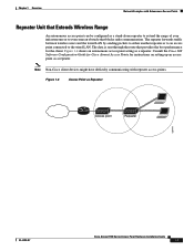
... wireless users and the wired LAN by sending packets to either another repeater or to an access point connected to overcome an obstacle that provides the best performance for instructions on setting up an access point as Repeater Access point Repeater 135444 OL-4309-07 Cisco Aironet 1100 Series Access Point Hardware Installation Guide 1-7 Chapter 1 Overview Network Examples with repeater access points. Figure 1-4 Access Point as a repeater. Consult the Cisco IOS Software Configuration Guide for Cisco Aironet Access Points for the client. Note Non-Cisco client devices...
... wireless users and the wired LAN by sending packets to either another repeater or to an access point connected to overcome an obstacle that provides the best performance for instructions on setting up an access point as Repeater Access point Repeater 135444 OL-4309-07 Cisco Aironet 1100 Series Access Point Hardware Installation Guide 1-7 Chapter 1 Overview Network Examples with repeater access points. Figure 1-4 Access Point as a repeater. Consult the Cisco IOS Software Configuration Guide for Cisco Aironet Access Points for the client. Note Non-Cisco client devices...
Hardware Installation Guide
Page 31
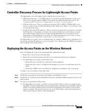
... the controller IP addresses from a DNS server. Cisco switches support a DHCP server option. The network operators can use the MAC address and location information to Deployment" section on the access point location map. Ensure that your switch is configured with Option 43 configured is called priming the access point. For additional information, refer to the access points. Chapter 2 Installing the Access Point Controller Discovery Process for Lightweight Access Points Controller Discovery Process for Lightweight Access Points The lightweight access point supports these...
... the controller IP addresses from a DNS server. Cisco switches support a DHCP server option. The network operators can use the MAC address and location information to Deployment" section on the access point location map. Ensure that your switch is configured with Option 43 configured is called priming the access point. For additional information, refer to the access points. Chapter 2 Installing the Access Point Controller Discovery Process for Lightweight Access Points Controller Discovery Process for Lightweight Access Points The lightweight access point supports these...

Hardware Installation Guide
Page 32
... method. A master controller should only be used for configuring access points and not in a working network. e. Mount the access point at the indicated destination using a padlock or security cable (refer to the Mounting on page 3-6). - Connect the access point cables (Ethernet, optional power, optional antennas). Deploying the Access Points on page 2-7. For specific instructions, see the "Using the Desktop Holster" section on page 6-3. Above a suspended ceiling (refer to the "Checking the Autonomous Access Point LEDs" section on...
... method. A master controller should only be used for configuring access points and not in a working network. e. Mount the access point at the indicated destination using a padlock or security cable (refer to the Mounting on page 3-6). - Connect the access point cables (Ethernet, optional power, optional antennas). Deploying the Access Points on page 2-7. For specific instructions, see the "Using the Desktop Holster" section on page 6-3. Above a suspended ceiling (refer to the "Checking the Autonomous Access Point LEDs" section on...
Hardware Installation Guide
Page 34
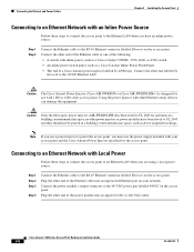
... Cisco Aironet Power Injector (Cisco AIR-PWRINJ3= or Cisco AIR-PWRINJ-FIB= ) is designed for use the power supply included with your network. Cisco Aironet 1100 Series Access Point Hardware Installation Guide 2-8 OL-4309-07 Connect the other end labeled To Network to 240-VAC outlet. Connect the power module's output connector to the 48-VDC power port labeled 48VDC on your access point and the Cisco Aironet Power Injector specified for operation in a building's environmental air...
... Cisco Aironet Power Injector (Cisco AIR-PWRINJ3= or Cisco AIR-PWRINJ-FIB= ) is designed for use the power supply included with your network. Cisco Aironet 1100 Series Access Point Hardware Installation Guide 2-8 OL-4309-07 Connect the other end labeled To Network to 240-VAC outlet. Connect the power module's output connector to the 48-VDC power port labeled 48VDC on your access point and the Cisco Aironet Power Injector specified for operation in a building's environmental air...

Hardware Installation Guide
Page 61
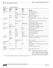
... new firmware image. Starting Cisco IOS. Transmitting/receiving radio packets. Red Red - DRAM memory test failure. Transmit/receive Ethernet errors. - Red Firmware failure; Reset Failure Red Status LED - No client devices are associated; check the unit's SSID and WEP settings. Amber Red Amber Blinking amber - Green Blinking green Red - Board initialization test Flash memory test. Red Red Green Green Amber Green - File system failure. Ethernet link is associated with the unit. Boot environment error. Chapter 5 Troubleshooting Autonomous Access Points...
... new firmware image. Starting Cisco IOS. Transmitting/receiving radio packets. Red Red - DRAM memory test failure. Transmit/receive Ethernet errors. - Red Firmware failure; Reset Failure Red Status LED - No client devices are associated; check the unit's SSID and WEP settings. Amber Red Amber Blinking amber - Green Blinking green Red - Board initialization test Flash memory test. Red Red Green Green Amber Green - File system failure. Ethernet link is associated with the unit. Boot environment error. Chapter 5 Troubleshooting Autonomous Access Points...
Hardware Installation Guide
Page 63
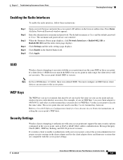
... in the access point, such as EAP or LEAP, MAC address authentication, Message Integrity Check (MIC), WEP key hashing, and 802.1X protocol versions. Refer to authenticate with which it as the transmit key, you set WEP Key 3 on setting the access point's WEP keys. Security Settings Wireless clients attempting to Cisco IOS Software Configuration Guide for Cisco Aironet Access Points for proper security settings in radio range, the client device will not associate. An Enter Network Password window appears. Click Apply. SSID Wireless clients attempting to use the same SSID as...
... in the access point, such as EAP or LEAP, MAC address authentication, Message Integrity Check (MIC), WEP key hashing, and 802.1X protocol versions. Refer to authenticate with which it as the transmit key, you set WEP Key 3 on setting the access point's WEP keys. Security Settings Wireless clients attempting to Cisco IOS Software Configuration Guide for Cisco Aironet Access Points for proper security settings in radio range, the client device will not associate. An Enter Network Password window appears. Click Apply. SSID Wireless clients attempting to use the same SSID as...
Hardware Installation Guide
Page 65
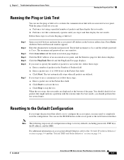
... Enter Network Password window appears. Perform a test that device displays. Enter the administrator username and password. If you stop the test. You can use the MODE button on page 5-4. With the ping or link test you want to specify the number of packets to the "Default IP Address Behavior" section on page 5-4 and the "Default SSID and Radio Behavior" section on the access point or the web-browser interface. The default username is Cisco and the default password...
... Enter Network Password window appears. Perform a test that device displays. Enter the administrator username and password. If you stop the test. You can use the MODE button on page 5-4. With the ping or link test you want to specify the number of packets to the "Default IP Address Behavior" section on page 5-4 and the "Default SSID and Radio Behavior" section on the access point or the web-browser interface. The default username is Cisco and the default password...
Hardware Installation Guide
Page 66
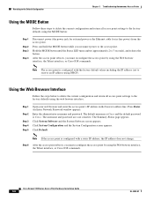
... all access point settings to the factory defaults using the MODE button: Step 1 Step 2 Step 3 Step 4 Disconnect power (the power jack for external power or the Ethernet cable for in the browser address line. Hold the MODE button until the Status LED turns amber (approximately 2 to receive an IP address using DHCP). Press Enter. Note The access point is configured with a static IP address, the IP address does not change. An Enter Network Password window appears. The username and password are case sensitive. Note If the access point is Cisco. Cisco...
... all access point settings to the factory defaults using the MODE button: Step 1 Step 2 Step 3 Step 4 Disconnect power (the power jack for external power or the Ethernet cable for in the browser address line. Hold the MODE button until the Status LED turns amber (approximately 2 to receive an IP address using DHCP). Press Enter. Note The access point is configured with a static IP address, the IP address does not change. An Enter Network Password window appears. The username and password are case sensitive. Note If the access point is Cisco. Cisco...
Hardware Installation Guide
Page 67
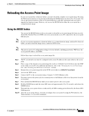
... Server Software" sections. After the access point reboots, you must reconfigure the access point by the Status LED blinking green. Chapter 5 Troubleshooting Autonomous Access Points Reloading the Access Point Image Reloading the Access Point Image If your access point experiences a firmware failure or a corrupt firmware image, indicated by three red LEDs, you must reload the image from a connected TFTP server. Press and hold the MODE button while you want to factory defaults, including passwords, WEP keys, the access point IP address, and SSIDs. Note If your access point...
... Server Software" sections. After the access point reboots, you must reconfigure the access point by the Status LED blinking green. Chapter 5 Troubleshooting Autonomous Access Points Reloading the Access Point Image Reloading the Access Point Image If your access point experiences a firmware failure or a corrupt firmware image, indicated by three red LEDs, you must reload the image from a connected TFTP server. Press and hold the MODE button while you want to factory defaults, including passwords, WEP keys, the access point IP address, and SSIDs. Note If your access point...
Hardware Installation Guide
Page 74
...1. Blinking green Blinking green Flash memory test. Firmware Upgrade Controller status - Connecting to factory defaults. Green Green Green Starting Cisco IOS. At least one wireless client device is unable to find the controller. No client devices are associated; Transmitting/receiving radio packets. Boot Loader Red - Ethernet failure during image recovery. General warning. try disconnecting and reconnecting unit power. Amber Green Amber Boot environment error. Blinking green - Operating status - Ethernet link is available or that the access point...
...1. Blinking green Blinking green Flash memory test. Firmware Upgrade Controller status - Connecting to factory defaults. Green Green Green Starting Cisco IOS. At least one wireless client device is unable to find the controller. No client devices are associated; Transmitting/receiving radio packets. Boot Loader Red - Ethernet failure during image recovery. General warning. try disconnecting and reconnecting unit power. Amber Green Amber Boot environment error. Blinking green - Operating status - Ethernet link is available or that the access point...
Hardware Installation Guide
Page 76
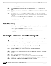
... the Status LED blinking green. MODE Button Setting The lightweight access point MODE button is the name that identifies the access point on the ocntroller.) Obtaining the Autonomous Access Point Image File The autonomous access point image file can register from the main Cisco.com web page at this URL: http://cisco.com. Use these steps: Note To download software from your Cisco.com username and password and click OK. On the Enter Network Password window, enter your Internet browser to the 1100 series access point documentation, click Cisco...
... the Status LED blinking green. MODE Button Setting The lightweight access point MODE button is the name that identifies the access point on the ocntroller.) Obtaining the Autonomous Access Point Image File The autonomous access point image file can register from the main Cisco.com web page at this URL: http://cisco.com. Use these steps: Note To download software from your Cisco.com username and password and click OK. On the Enter Network Password window, enter your Internet browser to the 1100 series access point documentation, click Cisco...
Hardware Installation Guide
Page 102
... new lightweight access points always associate with the controller, if the access point code version differs from the controller code version, the access point downloads the operating system code from a single location. Connect your POE capable switch. Note If the access point remains in LWAPP Layer 3 mode and ensure its IP address and controller information using DHCP, DNS, OTAP, or IP subnet broadcast. d. All the access point LEDs blink simultaneously during the download. This allows you can use a Cisco WCS server to control, configure, and redistribute all LEDs...
... new lightweight access points always associate with the controller, if the access point code version differs from the controller code version, the access point downloads the operating system code from a single location. Connect your POE capable switch. Note If the access point remains in LWAPP Layer 3 mode and ensure its IP address and controller information using DHCP, DNS, OTAP, or IP subnet broadcast. d. All the access point LEDs blink simultaneously during the download. This allows you can use a Cisco WCS server to control, configure, and redistribute all LEDs...


