Hardware Installation Guide
Page 4
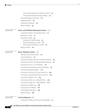
...Router Cabling Procedures 4-1 Cabling for Nonwireless Routers 4-2 Typical Installations 4-2 Connecting the Radio Antennas to the Wireless Router 4-6 Connecting the Power-over-Ethernet Module (Optional) 4-7 Connecting a Server, PC, or Workstation 4-8 Connecting an External Ethernet Switch (Optional) 4-9 Connecting a Broadband Modem 4-11 Connecting a Terminal or PC to the Console...4-21 Verifying Router Operations 4-24 What to Do Next 4-25 Initial Configuration 5-1 Installing Cisco Router and Security Device Manager 5-1 Cisco 850 Series and Cisco 870 Series Access Routers Hardware Installation ...
...Router Cabling Procedures 4-1 Cabling for Nonwireless Routers 4-2 Typical Installations 4-2 Connecting the Radio Antennas to the Wireless Router 4-6 Connecting the Power-over-Ethernet Module (Optional) 4-7 Connecting a Server, PC, or Workstation 4-8 Connecting an External Ethernet Switch (Optional) 4-9 Connecting a Broadband Modem 4-11 Connecting a Terminal or PC to the Console...4-21 Verifying Router Operations 4-24 What to Do Next 4-25 Initial Configuration 5-1 Installing Cisco Router and Security Device Manager 5-1 Cisco 850 Series and Cisco 870 Series Access Routers Hardware Installation ...

Hardware Installation Guide
Page 5
... 6-1 Before You Call Your Cisco Reseller 6-1 Problems During First Startup 6-2 Problems After the Router Is Running 6-3 Specifications A-1 Router Specifications A-1 Power-over-Ethernet Module Specifications A-2 LAN Port Pinouts A-3 Console Connector Pinouts A-4 ADSL Port Connector Pinouts A-4 Power Output Connector Pinouts A-5 Cable Specifications A-5 Ethernet Cable Specifications A-6 Maximum Cable Length A-6 Contents OL-5331-01 Cisco 850 Series and Cisco 870 Series Access Routers Hardware Installation Guide 5
... 6-1 Before You Call Your Cisco Reseller 6-1 Problems During First Startup 6-2 Problems After the Router Is Running 6-3 Specifications A-1 Router Specifications A-1 Power-over-Ethernet Module Specifications A-2 LAN Port Pinouts A-3 Console Connector Pinouts A-4 ADSL Port Connector Pinouts A-4 Power Output Connector Pinouts A-5 Cable Specifications A-5 Ethernet Cable Specifications A-6 Maximum Cable Length A-6 Contents OL-5331-01 Cisco 850 Series and Cisco 870 Series Access Routers Hardware Installation Guide 5

Hardware Installation Guide
Page 21
...Cisco 857 and Cisco 877 routers only. ISDN S/T port Cisco 876 and Cisco 878 routers only. OL-5331-01 Cisco 850 Series and Cisco 870 Series Access Routers Hardware Installation Guide 1-7 ports Compatible with a built-in switch Provides connection to 10/100BASE-T (10/100-Mbps) Ethernet networks. Provides connection to the ISDN service... • One G.SHDSL port • One RJ-45 console port Feature Summary Table 1-1 summarizes the features of these routers. Fast Ethernet WAN port Cisco 851 and Cisco 871 routers only. Does not support the autoswitch function. Provides connection to...
...Cisco 857 and Cisco 877 routers only. ISDN S/T port Cisco 876 and Cisco 878 routers only. OL-5331-01 Cisco 850 Series and Cisco 870 Series Access Routers Hardware Installation Guide 1-7 ports Compatible with a built-in switch Provides connection to 10/100BASE-T (10/100-Mbps) Ethernet networks. Provides connection to the ISDN service... • One G.SHDSL port • One RJ-45 console port Feature Summary Table 1-1 summarizes the features of these routers. Fast Ethernet WAN port Cisco 851 and Cisco 871 routers only. Does not support the autoswitch function. Provides connection to...

Hardware Installation Guide
Page 22
...Cisco 850 Series and Cisco 870 Series Access Routers Software Configuration Guide. The router is about to lose power, and sends a signal to be configured as an access point (AP) in hardware. The console port may be secured to a desktop or other PC or hub with a Cisco IOS Advanced IP Services... Dying gasp Detects whether the router is capable of 256 MB. Integrated 802.11b/g radio module (Optional) Provides connectivity to the terminal or PC for powered devices (such as security tokens and flash memory sticks. External power-over-Ethernet (PoE) module (Optional) ...
...Cisco 850 Series and Cisco 870 Series Access Routers Software Configuration Guide. The router is about to lose power, and sends a signal to be configured as an access point (AP) in hardware. The console port may be secured to a desktop or other PC or hub with a Cisco IOS Advanced IP Services... Dying gasp Detects whether the router is capable of 256 MB. Integrated 802.11b/g radio module (Optional) Provides connectivity to the terminal or PC for powered devices (such as security tokens and flash memory sticks. External power-over-Ethernet (PoE) module (Optional) ...

Hardware Installation Guide
Page 28
Hardware Features Figure 1-14 Installing the PoE Module Chapter 1 Product Overview 1 1 LEFT 0 SN: XXXNNNNXXXX LAN FE0 FE1 FE2 FE3 Cisco 871W WAN FE4 RESET CONSOLE AUX +5,+12 VDC RIGHT / PRIMARY 2 PWR 7 0 1 2 3 To LAN 5 3 6 4 1 Cisco 870 series router 2 Ethernet cables on the PoE module (four RJ-45 connectors in series) 3 PoE module 4 PoE power adapter 5 Router power adapter 6 PoE power plug 7 Router power plug 122351 1-14 Cisco 850 Series and Cisco 870 Series Access Routers Hardware Installation Guide OL-5331-01
Hardware Features Figure 1-14 Installing the PoE Module Chapter 1 Product Overview 1 1 LEFT 0 SN: XXXNNNNXXXX LAN FE0 FE1 FE2 FE3 Cisco 871W WAN FE4 RESET CONSOLE AUX +5,+12 VDC RIGHT / PRIMARY 2 PWR 7 0 1 2 3 To LAN 5 3 6 4 1 Cisco 870 series router 2 Ethernet cables on the PoE module (four RJ-45 connectors in series) 3 PoE module 4 PoE power adapter 5 Router power adapter 6 PoE power plug 7 Router power plug 122351 1-14 Cisco 850 Series and Cisco 870 Series Access Routers Hardware Installation Guide OL-5331-01

Hardware Installation Guide
Page 36
... does not provide specifications for Cisco Access Products with Cisco 850 Series and Cisco 870 Series Routers Cisco 851 and Cisco 857 and Item Cisco 871 Routers Cisco 877 Routers Cisco 876 Router Cisco 878 Router Ethernet cable(s) DSL1 cable ISDN4 S/T cable 2 Not applicable Not applicable 1 12 Not applicable 1 13 Optional 1 13 Optional Console cable Console-auxiliary5 cable 1 Optional 1 Optional 1 Optional 1 Optional Power adapter Power cord6 Cisco documentation7 1 1 1 1 1 1 1 1 1 1 1 1 Cisco Router and Security Device 1 1 1 1 Manager (SDM...
... does not provide specifications for Cisco Access Products with Cisco 850 Series and Cisco 870 Series Routers Cisco 851 and Cisco 857 and Item Cisco 871 Routers Cisco 877 Routers Cisco 876 Router Cisco 878 Router Ethernet cable(s) DSL1 cable ISDN4 S/T cable 2 Not applicable Not applicable 1 12 Not applicable 1 13 Optional 1 13 Optional Console cable Console-auxiliary5 cable 1 Optional 1 Optional 1 Optional 1 Optional Power adapter Power cord6 Cisco documentation7 1 1 1 1 1 1 1 1 1 1 1 1 Cisco Router and Security Device 1 1 1 1 Manager (SDM...
Hardware Installation Guide
Page 37
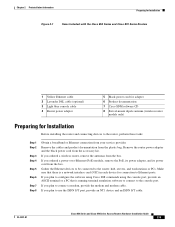
... the modem and modem cable. OL-5331-01 Cisco 850 Series and Cisco 870 Series Access Routers Hardware Installation Guide 2-5 Remove the cables and product documentation from the box. Chapter 2 Preinstallation Information Preparing for Installation Figure 2-1 Items Included with the Cisco 850 Series and Cisco 870 Series Routers 1 Yellow Ethernet cable 2 Lavender DSL cable (optional) 3 Light blue console cable 4 Router power adapter 5 Black power...
... the modem and modem cable. OL-5331-01 Cisco 850 Series and Cisco 870 Series Access Routers Hardware Installation Guide 2-5 Remove the cables and product documentation from the box. Chapter 2 Preinstallation Information Preparing for Installation Figure 2-1 Items Included with the Cisco 850 Series and Cisco 870 Series Routers 1 Yellow Ethernet cable 2 Lavender DSL cable (optional) 3 Light blue console cable 4 Router power adapter 5 Black power...

Hardware Installation Guide
Page 45
... Guide 4-1 It contains the following sections: • Cabling for Cisco 851, Cisco 857, Cisco 871, Cisco 876, Cisco 877, and Cisco 878 routers. CH A P T E R 4 Router Cabling Procedures This chapter describes the cabling procedures for Nonwireless Routers, page 4-2 • Typical Installations, page 4-2 • Connecting the Radio Antennas to the Wireless Router, page 4-6 • Connecting the Power-over -Ethernet (PoE) module should be mounted before you...
... Guide 4-1 It contains the following sections: • Cabling for Cisco 851, Cisco 857, Cisco 871, Cisco 876, Cisco 877, and Cisco 878 routers. CH A P T E R 4 Router Cabling Procedures This chapter describes the cabling procedures for Nonwireless Routers, page 4-2 • Typical Installations, page 4-2 • Connecting the Radio Antennas to the Wireless Router, page 4-6 • Connecting the Power-over -Ethernet (PoE) module should be mounted before you...

Hardware Installation Guide
Page 47
Chapter 4 Router Cabling Procedures Figure 4-1 Typical Installation of a Cisco 851 or Cisco 871 Router Typical Installations 1 LEFT 0 SN: XXXNNNNXXXX LAN FE4 0 FE3 1 FE2 2 FE1 3 Cisco 871W WAN FE4 RESET CONSOLE AUX +5,+12 VDC RIGHT / PRIMARY 1 2 3 4 5 1X 2X 1X 2X 1 Internet 1 Ethernet connection to an external switch 2 Ethernet connection to a PC 3 WAN connection using a broadband modem to the Internet 4 Console port 5 Power adapter 122237 OL-5331-01 Cisco 850 Series and Cisco 870 Series Access Routers Hardware Installation Guide 4-3
Chapter 4 Router Cabling Procedures Figure 4-1 Typical Installation of a Cisco 851 or Cisco 871 Router Typical Installations 1 LEFT 0 SN: XXXNNNNXXXX LAN FE4 0 FE3 1 FE2 2 FE1 3 Cisco 871W WAN FE4 RESET CONSOLE AUX +5,+12 VDC RIGHT / PRIMARY 1 2 3 4 5 1X 2X 1X 2X 1 Internet 1 Ethernet connection to an external switch 2 Ethernet connection to a PC 3 WAN connection using a broadband modem to the Internet 4 Console port 5 Power adapter 122237 OL-5331-01 Cisco 850 Series and Cisco 870 Series Access Routers Hardware Installation Guide 4-3

Hardware Installation Guide
Page 48
Typical Installations Figure 4-2 Typical Installation of a Cisco 857 or Cisco 877 Router Chapter 4 Router Cabling Procedures 122238 LEFT SN: XXXNNNNXXXX ETHERNET LAN FE3 4 FE2 3 FE1 2 FE0 1 Cisco 877W ADSLoPOTS RESET CONSOLE AUX +5,+12 VDC RIGHT / PRIMARY 1 2 3 4 5 1X 2X 1X 2X 1 1 Ethernet connection to an external switch 2 Ethernet connection to a PC 3 ADSL-over-POTS connection 4 Console port 5 Power adapter Cisco 850 Series and Cisco 870 Series Access Routers Hardware Installation Guide 4-4 OL-5331-01
Typical Installations Figure 4-2 Typical Installation of a Cisco 857 or Cisco 877 Router Chapter 4 Router Cabling Procedures 122238 LEFT SN: XXXNNNNXXXX ETHERNET LAN FE3 4 FE2 3 FE1 2 FE0 1 Cisco 877W ADSLoPOTS RESET CONSOLE AUX +5,+12 VDC RIGHT / PRIMARY 1 2 3 4 5 1X 2X 1X 2X 1 1 Ethernet connection to an external switch 2 Ethernet connection to a PC 3 ADSL-over-POTS connection 4 Console port 5 Power adapter Cisco 850 Series and Cisco 870 Series Access Routers Hardware Installation Guide 4-4 OL-5331-01

Hardware Installation Guide
Page 49
Chapter 4 Router Cabling Procedures Figure 4-3 Typical Installation of a Cisco 876 Router Typical Installations 122239 LEFT Cisco 876W SN: XXXNNNNXXXX LAN FE0 FE1 FE2 FE3 ISDN S/T ADSL o ISDN RESET CONSOLE AUX +5,+12 VDC RIGHT / PRIMARY 1 23 45 6 1X 2X 1X 2X 1 1 Ethernet connection to an external switch 2 Ethernet connection to a PC 3 ISDN S/T connection 4 ADSL-over-ISDN connection 5 Console port 6 Power adapter OL-5331-01 Cisco 850 Series and Cisco 870 Series Access Routers Hardware Installation Guide 4-5
Chapter 4 Router Cabling Procedures Figure 4-3 Typical Installation of a Cisco 876 Router Typical Installations 122239 LEFT Cisco 876W SN: XXXNNNNXXXX LAN FE0 FE1 FE2 FE3 ISDN S/T ADSL o ISDN RESET CONSOLE AUX +5,+12 VDC RIGHT / PRIMARY 1 23 45 6 1X 2X 1X 2X 1 1 Ethernet connection to an external switch 2 Ethernet connection to a PC 3 ISDN S/T connection 4 ADSL-over-ISDN connection 5 Console port 6 Power adapter OL-5331-01 Cisco 850 Series and Cisco 870 Series Access Routers Hardware Installation Guide 4-5

Hardware Installation Guide
Page 50
.... Connecting the Radio Antennas to the Wireless Router Figure 4-4 Typical Installation of a Cisco 878 Router Chapter 4 Router Cabling Procedures LEFT Cisco 878W SN: XXXNNNNXXXX LAN FE0 FE1 FE2 FE3 ISDN S/T G.SHDSL RESET CONSOLE AUX +5,+12 VDC RIGHT / PRIMARY 1 23 45 6 122240 1X 2X 1X 2X 1 1 Ethernet connection to an external switch 2 Ethernet connection to a PC 3 ISDN S/T connection 4 G.SHDSL connection...
.... Connecting the Radio Antennas to the Wireless Router Figure 4-4 Typical Installation of a Cisco 878 Router Chapter 4 Router Cabling Procedures LEFT Cisco 878W SN: XXXNNNNXXXX LAN FE0 FE1 FE2 FE3 ISDN S/T G.SHDSL RESET CONSOLE AUX +5,+12 VDC RIGHT / PRIMARY 1 23 45 6 122240 1X 2X 1X 2X 1 1 Ethernet connection to an external switch 2 Ethernet connection to a PC 3 ISDN S/T connection 4 G.SHDSL connection...

Hardware Installation Guide
Page 51
... Figure 4-5. Chapter 4 Router Cabling Procedures Connecting the Power-over-Ethernet Module (Optional) Connecting the Power-over-Ethernet Module (Optional) If you purchased a power-over -Ethernet Module to the Router 2 1 1 LEFT 0 5 Cisco 871W LAN FE0 FE1 FE2 FE3 0 1 2 3 To LAN WAN FE4 RESET CONSOLE AUX +5,+12 VDC 3 PWR 4 RIGHT / PRIMARY 121035 1 Router 4 PoE module 2 Router Ethernet ports 5 Plastic cable guard 3 Ethernet cables connecting the PoE...
... Figure 4-5. Chapter 4 Router Cabling Procedures Connecting the Power-over-Ethernet Module (Optional) Connecting the Power-over-Ethernet Module (Optional) If you purchased a power-over -Ethernet Module to the Router 2 1 1 LEFT 0 5 Cisco 871W LAN FE0 FE1 FE2 FE3 0 1 2 3 To LAN WAN FE4 RESET CONSOLE AUX +5,+12 VDC 3 PWR 4 RIGHT / PRIMARY 121035 1 Router 4 PoE module 2 Router Ethernet ports 5 Plastic cable guard 3 Ethernet cables connecting the PoE...

Hardware Installation Guide
Page 52
... Access Routers Hardware Installation Guide 4-8 OL-5331-01 Figure 4-6 Connecting a Server, PC, or Workstation 2 1 1 LEFT 0 Cisco 871W LAN WAN FE4 0 FE3 1 FE2 2 FE1 3 FE4 RESET CONSOLE AUX +5,+12 VDC 3 RIGHT / PRIMARY 4 5 117971 1 Router 2 Yellow Ethernet cable 3 Built-in Ethernet switch port, follow the steps given after Figure 4-6, which shows a Cisco 871 router connected to Cisco 850 series and Cisco 870 series routers.
... Access Routers Hardware Installation Guide 4-8 OL-5331-01 Figure 4-6 Connecting a Server, PC, or Workstation 2 1 1 LEFT 0 Cisco 871W LAN WAN FE4 0 FE3 1 FE2 2 FE1 3 FE4 RESET CONSOLE AUX +5,+12 VDC 3 RIGHT / PRIMARY 4 5 117971 1 Router 2 Yellow Ethernet cable 3 Built-in Ethernet switch port, follow the steps given after Figure 4-6, which shows a Cisco 871 router connected to Cisco 850 series and Cisco 870 series routers.

Hardware Installation Guide
Page 54
... (Optional) Figure 4-7 Connecting to an Ethernet Switch Chapter 4 Router Cabling Procedures 1 LEFT 0 Cisco 871W LAN WAN FE4 0 FE3 1 FE2 2 FE1 3 FE4 RESET CONSOLE AUX +5,+12 VDC 1 RIGHT / PRIMARY 117972 SYSTEM RPS MODE STATUS UTIL DUPLX SPEED 1 1X 23 45 67 8 9 10 11 12 15X 2X 16X 2 1 1X 23 ...
... (Optional) Figure 4-7 Connecting to an Ethernet Switch Chapter 4 Router Cabling Procedures 1 LEFT 0 Cisco 871W LAN WAN FE4 0 FE3 1 FE2 2 FE1 3 FE4 RESET CONSOLE AUX +5,+12 VDC 1 RIGHT / PRIMARY 117972 SYSTEM RPS MODE STATUS UTIL DUPLX SPEED 1 1X 23 45 67 8 9 10 11 12 15X 2X 16X 2 1 1X 23 ...
Hardware Installation Guide
Page 55
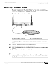
.... Figure 4-8 Connecting to a Broadband Modem 1 LEFT 0 Cisco 871W LAN WAN FE0 FE1 FE2 FE3 FE4 RESET CONSOLE AUX +5,+12 VDC 1 RIGHT / PRIMARY ETHERNET POWER 575-LRE Cisco 117973 ACTIVITY WAN 2 1 Ethernet WAN port on the router 2 Available port on the modem to connect to an available port on . Chapter 4 Router Cabling Procedures Connecting a Broadband Modem Connecting a Broadband Modem...
.... Figure 4-8 Connecting to a Broadband Modem 1 LEFT 0 Cisco 871W LAN WAN FE0 FE1 FE2 FE3 FE4 RESET CONSOLE AUX +5,+12 VDC 1 RIGHT / PRIMARY ETHERNET POWER 575-LRE Cisco 117973 ACTIVITY WAN 2 1 Ethernet WAN port on the router 2 Available port on the modem to connect to an available port on . Chapter 4 Router Cabling Procedures Connecting a Broadband Modem Connecting a Broadband Modem...

Hardware Installation Guide
Page 67
... PoE Module 1 1 LEFT 0 SN: XXXNNNNXXXX LAN FE0 FE1 FE2 FE3 Cisco 871W WAN FE4 RESET CONSOLE AUX +5,+12 VDC RIGHT / PRIMARY 2 PWR 7 0 1 2 3 To LAN 5 3 6 4 122351 1 Router 2 Ethernet cables on the PoE module 3 PoE module 4 PoE module power adapter 5 Router power adapter 6 PoE module power adapter plug 7 Router power adapter plug Perform the following steps to connect power...
... PoE Module 1 1 LEFT 0 SN: XXXNNNNXXXX LAN FE0 FE1 FE2 FE3 Cisco 871W WAN FE4 RESET CONSOLE AUX +5,+12 VDC RIGHT / PRIMARY 2 PWR 7 0 1 2 3 To LAN 5 3 6 4 122351 1 Router 2 Ethernet cables on the PoE module 3 PoE module 4 PoE module power adapter 5 Router power adapter 6 PoE module power adapter plug 7 Router power adapter plug Perform the following steps to connect power...

Hardware Installation Guide
Page 78
... Ethernet switch, and make sure that it is receiving power. • Check with the Internet service provider or corporate network administrator to determine whether there is damaged, order another cable from Cisco, or replace it is connected to configure the router, or configure the router using the correct cable. Make sure that is damaged, order another cable from Cisco...
... Ethernet switch, and make sure that it is receiving power. • Check with the Internet service provider or corporate network administrator to determine whether there is damaged, order another cable from Cisco, or replace it is connected to configure the router, or configure the router using the correct cable. Make sure that is damaged, order another cable from Cisco...

Hardware Installation Guide
Page 81
...Ethernet Module Specifications, page A-2 • LAN Port Pinouts, page A-3 • Console Connector Pinouts, page A-4 • ADSL Port Connector Pinouts, page A-4 • Power Output Connector Pinouts, page A-5 • Cable Specifications, page A-5 Router Specifications Table A-1 outlines the system specifications for Cisco 850 series and Cisco 870 series routers. Table A-1 Router... 0 to 10,000 ft (3000 m) OL-5331-01 Cisco 850 Series and Cisco 870 Series Access Routers Hardware Installation Guide A-1 Specifications A A P P E N D I X This appendix provides system, port, and...
...Ethernet Module Specifications, page A-2 • LAN Port Pinouts, page A-3 • Console Connector Pinouts, page A-4 • ADSL Port Connector Pinouts, page A-4 • Power Output Connector Pinouts, page A-5 • Cable Specifications, page A-5 Router Specifications Table A-1 outlines the system specifications for Cisco 850 series and Cisco 870 series routers. Table A-1 Router... 0 to 10,000 ft (3000 m) OL-5331-01 Cisco 850 Series and Cisco 870 Series Access Routers Hardware Installation Guide A-1 Specifications A A P P E N D I X This appendix provides system, port, and...

Hardware Installation Guide
Page 87
... to router 11 C cables autosensing in router 8 maximum length 6 specifications (table) 6 caution, defined 8 Cisco reseller, contacting 1 Cisco Router and Security Device Manager 1 CLI for initial configuration 4 connecting AC adapter 21 ADSL-over-ISDN port 17 ADSL-over-POTS port 16 async modem to the console port 13 broadband modem 11 console port to async modem 13 external Ethernet switch...
... to router 11 C cables autosensing in router 8 maximum length 6 specifications (table) 6 caution, defined 8 Cisco reseller, contacting 1 Cisco Router and Security Device Manager 1 CLI for initial configuration 4 connecting AC adapter 21 ADSL-over-ISDN port 17 ADSL-over-POTS port 16 async modem to the console port 13 broadband modem 11 console port to async modem 13 external Ethernet switch...


