
Phone Guide
Page 13
The following graphic and table show how to connect the Cisco Unified IP Phone 7906G: 3 2 5 1 4 1 Network port (10/100 SW) 2 Handset port 3 DC adapter port (DC48V) 79976 4 AC-to the corporate IP telephony network. Connecting Your Phone Connecting Your Phone Your system administrator will likely connect your phone. If that is not the case, refer to the graphics below to connect your new Cisco Unified IP Phone to -DC power supply 5 AC power cord Cisco Unified IP Phone 7906G and 7911G for Cisco Unified Communications Manager 7.0 5
The following graphic and table show how to connect the Cisco Unified IP Phone 7906G: 3 2 5 1 4 1 Network port (10/100 SW) 2 Handset port 3 DC adapter port (DC48V) 79976 4 AC-to the corporate IP telephony network. Connecting Your Phone Connecting Your Phone Your system administrator will likely connect your phone. If that is not the case, refer to the graphics below to connect your new Cisco Unified IP Phone to -DC power supply 5 AC power cord Cisco Unified IP Phone 7906G and 7911G for Cisco Unified Communications Manager 7.0 5

Phone Guide
Page 14
The following graphic and table show how to connect the Cisco Unified IP Phone 7911G: 4 3 6 1 2 5 1 Network port (10/100 SW) 2 Access port (10/100 PC) 3 Handset port 91638 4 DC adapter port (DC48V) 5 AC-to-DC power supply 6 AC power cord 6 OL-15428-01
The following graphic and table show how to connect the Cisco Unified IP Phone 7911G: 4 3 6 1 2 5 1 Network port (10/100 SW) 2 Access port (10/100 PC) 3 Handset port 91638 4 DC adapter port (DC48V) 5 AC-to-DC power supply 6 AC power cord 6 OL-15428-01

Administration Guide
Page 83
... with Your Cisco Unified IP Phone" section on page 2-4. When connecting phones powered by an external power supply, you must connect the power supply to the phone before connecting the Ethernet cable to the phone. To install a Cisco Unified IP Phone, perform these steps: Procedure Notes Reference 1. Connect the footstand to the Cisco DC Adapter port (DC48V). OL11954-01 Cisco Unified IP Phone 7906G and 7911G for a graphical...
... with Your Cisco Unified IP Phone" section on page 2-4. When connecting phones powered by an external power supply, you must connect the power supply to the phone before connecting the Ethernet cable to the phone. To install a Cisco Unified IP Phone, perform these steps: Procedure Notes Reference 1. Connect the footstand to the Cisco DC Adapter port (DC48V). OL11954-01 Cisco Unified IP Phone 7906G and 7911G for a graphical...

Administration Guide
Page 87
Chapter 3 Setting Up the Cisco Unified IP Phone Installing the Cisco Unified IP Phone Figure 3-3 Cisco Unified IP Phone Model 7906G Cable Connections 3 10/100 SW 1 4 5 1 Network port (10/100 SW) 2 Handset port 3 DC Adapter port (DC48V) 154390 2 4 AC-to-DC power supply 5 AC power cord OL11954-01 Cisco Unified IP Phone 7906G and 7911G for Cisco Unified Communications Manager 6.0 3-13
Chapter 3 Setting Up the Cisco Unified IP Phone Installing the Cisco Unified IP Phone Figure 3-3 Cisco Unified IP Phone Model 7906G Cable Connections 3 10/100 SW 1 4 5 1 Network port (10/100 SW) 2 Handset port 3 DC Adapter port (DC48V) 154390 2 4 AC-to-DC power supply 5 AC power cord OL11954-01 Cisco Unified IP Phone 7906G and 7911G for Cisco Unified Communications Manager 6.0 3-13

Administration Guide
Page 88
Installing the Cisco Unified IP Phone Chapter 3 Setting Up the Cisco Unified IP Phone Figure 3-4 Cisco Unified IP Phone Model 7911G Cable Connections 4 3 6 1 2 5 91638 1 Network port (10/100 SW) 2 Access port (10/100 PC) 3 Handset port 4 DC Adapter port (DC48V) 5 AC-to-DC power supply 6 AC power cord Related Topics • Before You Begin, page 3-2 • Mounting the Phone to a Wall, page 3-15 • Configuring Startup Network Settings, page 3-17 3-14 Cisco Unified IP Phone 7906G and 7911G for Cisco Unified Communications Manager 6.0 OL11954-01
Installing the Cisco Unified IP Phone Chapter 3 Setting Up the Cisco Unified IP Phone Figure 3-4 Cisco Unified IP Phone Model 7911G Cable Connections 4 3 6 1 2 5 91638 1 Network port (10/100 SW) 2 Access port (10/100 PC) 3 Handset port 4 DC Adapter port (DC48V) 5 AC-to-DC power supply 6 AC power cord Related Topics • Before You Begin, page 3-2 • Mounting the Phone to a Wall, page 3-15 • Configuring Startup Network Settings, page 3-17 3-14 Cisco Unified IP Phone 7906G and 7911G for Cisco Unified Communications Manager 6.0 OL11954-01
Administration Guide
Page 268
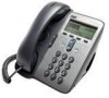
... the maximum cable length between each Cisco Unified IP Phone and the switch is 100 meters (330 feet). Cisco Unified IP Phone 7906G and 7911G for the access port 10/100BaseT connection (labeled 10/100 PC). • 48-volt power connector. Cable Specifications • RJ... Specification Value or Range Power options • The phone can receive power from IEEE 802.3af-compliant data switches (Class III) • The phone can be powered locally with a power adapter (Cisco part number CP-PWR-CUBE-3=) and the appropriate power cord (power requirements for the power adapter: 100-240 VAC, 50...
... the maximum cable length between each Cisco Unified IP Phone and the switch is 100 meters (330 feet). Cisco Unified IP Phone 7906G and 7911G for the access port 10/100BaseT connection (labeled 10/100 PC). • 48-volt power connector. Cable Specifications • RJ... Specification Value or Range Power options • The phone can receive power from IEEE 802.3af-compliant data switches (Class III) • The phone can be powered locally with a power adapter (Cisco part number CP-PWR-CUBE-3=) and the appropriate power cord (power requirements for the power adapter: 100-240 VAC, 50...

