

Installation Guide
Page 2
...the television or radio. • Move the equipment farther away from the television or radio. (That is causing interference by Cisco Systems, Inc. THE SPECIFICATIONS AND INFORMATION REGARDING THE PRODUCTS IN THIS MANUAL ARE SUBJECT TO CHANGE WITHOUT NOTICE. IF YOU ARE UNABLE TO LOCATE THE ...SOFTWARE LICENSE OR LIMITED WARRANTY, CONTACT YOUR CISCO REPRESENTATIVE FOR A COPY. In that event, your right to use the equipment may cause interference with the specifications in part 15 of this equipment in accordance with radio and television reception. All...
...the television or radio. • Move the equipment farther away from the television or radio. (That is causing interference by Cisco Systems, Inc. THE SPECIFICATIONS AND INFORMATION REGARDING THE PRODUCTS IN THIS MANUAL ARE SUBJECT TO CHANGE WITHOUT NOTICE. IF YOU ARE UNABLE TO LOCATE THE ...SOFTWARE LICENSE OR LIMITED WARRANTY, CONTACT YOUR CISCO REPRESENTATIVE FOR A COPY. In that event, your right to use the equipment may cause interference with the specifications in part 15 of this equipment in accordance with radio and television reception. All...
Installation Guide
Page 8
... and DC-Input Power Supplies A-38 4000 W Power Supply Specifications A-39 4000 W Power Supply AC Power Cords A-42 6000 W AC-Input Power Supply A-43 6000 W Power Supply Specifications A-44 6000 W Power Supply AC Power Cords A-46 AC... Power Cord Illustrations A-47 Power Supply Redundancy A-57 B A P P E N D I X Transceivers, Module Connectors, and Cable Specifications B-1 Transceivers B-1 100-MB Transceiver Modules B-2 1-GB Transceiver Modules B-3 10-GB Transceiver Modules B-8 WDM Transceiver Modules B-10 Catalyst 6500 Series Switches...
... and DC-Input Power Supplies A-38 4000 W Power Supply Specifications A-39 4000 W Power Supply AC Power Cords A-42 6000 W AC-Input Power Supply A-43 6000 W Power Supply Specifications A-44 6000 W Power Supply AC Power Cords A-46 AC... Power Cord Illustrations A-47 Power Supply Redundancy A-57 B A P P E N D I X Transceivers, Module Connectors, and Cable Specifications B-1 Transceivers B-1 100-MB Transceiver Modules B-2 1-GB Transceiver Modules B-3 10-GB Transceiver Modules B-8 WDM Transceiver Modules B-10 Catalyst 6500 Series Switches...
Installation Guide
Page 11
.... OL-5781-04 Catalyst 6500 Series Switches Installation Guide xi Installing the Switch Describes how to consider when preparing your Catalyst 6500 series switch. Removal and Provides procedures for the Catalyst 6500 series switch AC-input and DC-input power supplies and the AC power cords. Power Supply Specifications Provides specifications for removing and installing chassis Replacement Procedures components. Organization...
.... OL-5781-04 Catalyst 6500 Series Switches Installation Guide xi Installing the Switch Describes how to consider when preparing your Catalyst 6500 series switch. Removal and Provides procedures for the Catalyst 6500 series switch AC-input and DC-input power supplies and the AC power cords. Power Supply Specifications Provides specifications for removing and installing chassis Replacement Procedures components. Organization...
Installation Guide
Page 12
... quotation marks around the string or the string will include the quotation marks. Catalyst 6500 Series Switches Installation Guide xii OL-5781-04 Conventions Preface Chapter Appendix B Appendix C Appendix D Appendix E Title Transceivers, Module Connectors, and Cable Specifications Repacking the Switch Chassis and Module Power and Heat Values Troubleshooting Description Gives brief descriptions of characters. Optional...
... quotation marks around the string or the string will include the quotation marks. Catalyst 6500 Series Switches Installation Guide xii OL-5781-04 Conventions Preface Chapter Appendix B Appendix C Appendix D Appendix E Title Transceivers, Module Connectors, and Cable Specifications Repacking the Switch Chassis and Module Power and Heat Values Troubleshooting Description Gives brief descriptions of characters. Optional...
Installation Guide
Page 26
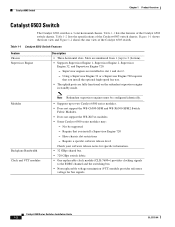
... front view and Figure 1-2 shows the rear view of the Catalyst 6503 switch chassis. Modules Backplane Bandwidth Clock and VTT modules Note Redundant supervisor engines must be supported - Require a specific software release level Check your software release notes for bus signals...support the WS-C6500-SFM and WS-X6500-SFM2 Switch Fabric Modules. • Does not support the WS-X67xx modules. • Some Catalyst 6500 series modules may: - Table 1-2 lists the specifications of the Catalyst 6503 switch chassis. Have chassis slot restrictions - Supervisor engines are numbered from 1 ...
... front view and Figure 1-2 shows the rear view of the Catalyst 6503 switch chassis. Modules Backplane Bandwidth Clock and VTT modules Note Redundant supervisor engines must be supported - Require a specific software release level Check your software release notes for bus signals...support the WS-C6500-SFM and WS-X6500-SFM2 Switch Fabric Modules. • Does not support the WS-X67xx modules. • Some Catalyst 6500 series modules may: - Table 1-2 lists the specifications of the Catalyst 6503 switch chassis. Have chassis slot restrictions - Supervisor engines are numbered from 1 ...

Installation Guide
Page 29
... and 200 Hz. 5 dB/octave roll off at 55°C (131°F) generating a major alarm. OL-5781-04 Catalyst 6500 Series Switches Installation Guide 1-5 Chapter 1 Product Overview Catalyst 6503 Switch Table 1-2 Catalyst 6503 Switch Specifications Item Environmental Temperature, operating Specification Certified for operation: 32° to 104°F (0° to 40°C) Designed and tested for operation: 32...
... and 200 Hz. 5 dB/octave roll off at 55°C (131°F) generating a major alarm. OL-5781-04 Catalyst 6500 Series Switches Installation Guide 1-5 Chapter 1 Product Overview Catalyst 6503 Switch Table 1-2 Catalyst 6503 Switch Specifications Item Environmental Temperature, operating Specification Certified for operation: 32° to 104°F (0° to 40°C) Designed and tested for operation: 32...
Installation Guide
Page 30
On Catalyst chassis in which the airflow is designed to bottom) Catalyst 6500 Series Switches Installation Guide 1-6 OL-5781-04 Failure to maintain adequate air space can cause the chassis to overheat and the system to back, the chassis may be placed side-by-side. Catalyst 6503 Switch Chapter 1 Product Overview Table 1-2 Catalyst 6503 Switch Specifications (continued) Item Physical Characteristics Dimensions (H x W x D) Weight...
On Catalyst chassis in which the airflow is designed to bottom) Catalyst 6500 Series Switches Installation Guide 1-6 OL-5781-04 Failure to maintain adequate air space can cause the chassis to overheat and the system to back, the chassis may be placed side-by-side. Catalyst 6503 Switch Chapter 1 Product Overview Table 1-2 Catalyst 6503 Switch Specifications (continued) Item Physical Characteristics Dimensions (H x W x D) Weight...
Installation Guide
Page 32
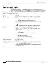
... 1-4 shows the rear view of the Catalyst 6503-E switch. Have chassis slot restrictions - Catalyst 6503-E Switch Chapter 1 Product Overview Catalyst 6503-E Switch The Catalyst 6503-E switch is a 3-slot horizontal chassis. Not be configured identically. • Supports up to the EOBC channel and the switching bus. • Non-replaceable voltage termination (VTT) module provides reference voltage for specific information. • 32 GBps shared...
... 1-4 shows the rear view of the Catalyst 6503-E switch. Have chassis slot restrictions - Catalyst 6503-E Switch Chapter 1 Product Overview Catalyst 6503-E Switch The Catalyst 6503-E switch is a 3-slot horizontal chassis. Not be configured identically. • Supports up to the EOBC channel and the switching bus. • Non-replaceable voltage termination (VTT) module provides reference voltage for specific information. • 32 GBps shared...

Installation Guide
Page 34
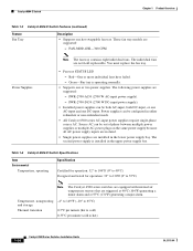
Catalyst 6503-E Switch Chapter 1 Product Overview Table 1-4 Catalyst 6503-E Switch Specifications Item Environmental Temperature, operating Specification Certified for operation: 32° to 104°F (0° to 40°C) Designed and tested for operation: -200 to 10000 feet (-60 to 3000 m) This switch complies with internal ...0 to 6500 feet Designed and tested for operation: 32° to 130°F (0° to 55°C) Note The Catalyst 6500 series switches are equipped with Network Equipment Building Systems (NEBS) (Zone 4 per axis (1.12 Grms). 64 to an ambient temperature of...
Catalyst 6503-E Switch Chapter 1 Product Overview Table 1-4 Catalyst 6503-E Switch Specifications Item Environmental Temperature, operating Specification Certified for operation: 32° to 104°F (0° to 40°C) Designed and tested for operation: -200 to 10000 feet (-60 to 3000 m) This switch complies with internal ...0 to 6500 feet Designed and tested for operation: 32° to 130°F (0° to 55°C) Note The Catalyst 6500 series switches are equipped with Network Equipment Building Systems (NEBS) (Zone 4 per axis (1.12 Grms). 64 to an ambient temperature of...
Installation Guide
Page 35
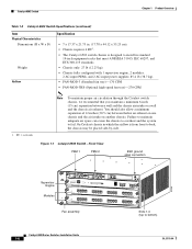
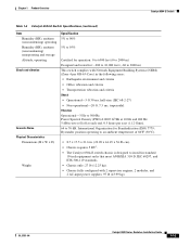
... and the system to back, the chassis may be placed side-by-side. Chapter 1 Product Overview Catalyst 6503-E Switch Table 1-4 Catalyst 6503-E Switch Specifications (continued) Item Physical Characteristics Dimensions (H x W x D) Weight Airflow Specification • 7 x 17.37 x 21.75 in. (17.78 x 44.12 x 55.25 cm). • Chassis requires 4 RU1. • The Catalyst 6503-E switch chassis is designed to install in which...
... and the system to back, the chassis may be placed side-by-side. Chapter 1 Product Overview Catalyst 6503-E Switch Table 1-4 Catalyst 6503-E Switch Specifications (continued) Item Physical Characteristics Dimensions (H x W x D) Weight Airflow Specification • 7 x 17.37 x 21.75 in. (17.78 x 44.12 x 55.25 cm). • Chassis requires 4 RU1. • The Catalyst 6503-E switch chassis is designed to install in which...
Installation Guide
Page 37
... series modules may: - Require that you install a Supervisor Engine 720 - Figure 1-5 shows the front view and Figure 1-6 shows the rear view of the Catalyst 6504-E switch chassis. Require a specific software release level Check your software release notes for bus signals. Slots are fully functional on the redundant supervisor engine in slot 1 and slot 2. •...
... series modules may: - Require that you install a Supervisor Engine 720 - Figure 1-5 shows the front view and Figure 1-6 shows the rear view of the Catalyst 6504-E switch chassis. Require a specific software release level Check your software release notes for bus signals. Slots are fully functional on the redundant supervisor engine in slot 1 and slot 2. •...
Installation Guide
Page 38
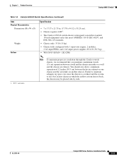
...-4HS-300 CFM Power Supplies Note The fan tray contains eight individual fans. PWR-2700-AC/4 (2700 W AC-input power supply). - Table 1-6 Catalyst 6504-E Switch Specifications Item Environmental Temperature, operating Specification Certified for operation: 32° to 104°F (0° to 40°C) Designed and tested for operation: 32° to 130°F (0°...
...-4HS-300 CFM Power Supplies Note The fan tray contains eight individual fans. PWR-2700-AC/4 (2700 W AC-input power supply). - Table 1-6 Catalyst 6504-E Switch Specifications Item Environmental Temperature, operating Specification Certified for operation: 32° to 104°F (0° to 40°C) Designed and tested for operation: 32° to 130°F (0°...
Installation Guide
Page 39
... modules, and 2 AC-input power supplies: 97 lb (43.99 kg). OL-5781-04 Catalyst 6500 Series Switches Installation Guide 1-15 Chapter 1 Product Overview Catalyst 6504-E Switch Table 1-6 Catalyst 6504-E Switch Specifications (continued) Item Humidity (RH), ambient (noncondensing) operating Humidity (RH), ambient (noncondensing) nonoperating ...19-inch equipment racks that meet ANSI/EIA 310-D, IEC 60297, and ETS 300-119 standards. • Chassis only: 27 lb (12.25 kg). • Chassis fully configured with Network Equipment Building Systems (NEBS) (Zone 4 per GR-63-Core) in the following ...
... modules, and 2 AC-input power supplies: 97 lb (43.99 kg). OL-5781-04 Catalyst 6500 Series Switches Installation Guide 1-15 Chapter 1 Product Overview Catalyst 6504-E Switch Table 1-6 Catalyst 6504-E Switch Specifications (continued) Item Humidity (RH), ambient (noncondensing) operating Humidity (RH), ambient (noncondensing) nonoperating ...19-inch equipment racks that meet ANSI/EIA 310-D, IEC 60297, and ETS 300-119 standards. • Chassis only: 27 lb (12.25 kg). • Chassis fully configured with Network Equipment Building Systems (NEBS) (Zone 4 per GR-63-Core) in the following ...

Installation Guide
Page 40
On Catalyst chassis in which the airflow is from front to fail. Failure to maintain adequate air space can cause the chassis to overheat and the system to back, the chassis may be placed side-by-side. Catalyst 6504-E Switch Chapter 1 Product Overview Table 1-6 Catalyst 6504-E Switch Specifications (continued) Item Airflow Specification • FAN-MOD-4HS-300 CFM 1. You should also...
On Catalyst chassis in which the airflow is from front to fail. Failure to maintain adequate air space can cause the chassis to overheat and the system to back, the chassis may be placed side-by-side. Catalyst 6504-E Switch Chapter 1 Product Overview Table 1-6 Catalyst 6504-E Switch Specifications (continued) Item Airflow Specification • FAN-MOD-4HS-300 CFM 1. You should also...
Installation Guide
Page 42
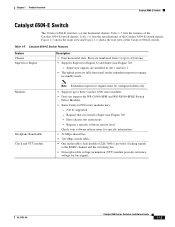
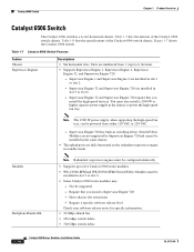
... Engine 2 are fully functional on the redundant supervisor engine in switching fabric. Supervisor Engine 32 and Supervisor Engine 720 are not supported by Supervisor Engine 720 and cannot be supported - Require that you install a Supervisor Engine 720 - Table 1-8 lists the specifications of the Catalyst 6506 switch chassis. Supervisor Engine 720 has built-in standby mode...
... Engine 2 are fully functional on the redundant supervisor engine in switching fabric. Supervisor Engine 32 and Supervisor Engine 720 are not supported by Supervisor Engine 720 and cannot be supported - Require that you install a Supervisor Engine 720 - Table 1-8 lists the specifications of the Catalyst 6506 switch chassis. Supervisor Engine 720 has built-in standby mode...

Installation Guide
Page 45
International Organization for operation: 32° to 130°F (0° to 55°C) Note The Catalyst 6500 series switches are triggered at 40°C (104°F) generating a minor alarm and at each end. 0.5 hours per ... roll off at 55°C (131°F) generating a major alarm. OL-5781-04 Catalyst 6500 Series Switches Installation Guide 1-21 Chapter 1 Product Overview Catalyst 6506 Switch Table 1-8 Catalyst 6506 Switch Specifications Item Environmental Temperature, operating Specification Certified for operation: 32° to 104°F (0° to 40°C) Designed ...
International Organization for operation: 32° to 130°F (0° to 55°C) Note The Catalyst 6500 series switches are triggered at 40°C (104°F) generating a minor alarm and at each end. 0.5 hours per ... roll off at 55°C (131°F) generating a major alarm. OL-5781-04 Catalyst 6500 Series Switches Installation Guide 1-21 Chapter 1 Product Overview Catalyst 6506 Switch Table 1-8 Catalyst 6506 Switch Specifications Item Environmental Temperature, operating Specification Certified for operation: 32° to 104°F (0° to 40°C) Designed ...
Installation Guide
Page 46
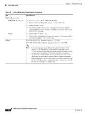
...) between a wall and the chassis air intake or a wall and the chassis air exhaust. On Catalyst chassis in standard 19-inch equipment racks that you maintain a minimum 6-inch (15 cm) separation between the hot air exhaust on one chassis and the air intake on another chassis. Catalyst 6506 Switch Chapter 1 Product Overview Table 1-8 Catalyst 6506 Switch Specifications (continued) Item Physical Characteristics...
...) between a wall and the chassis air intake or a wall and the chassis air exhaust. On Catalyst chassis in standard 19-inch equipment racks that you maintain a minimum 6-inch (15 cm) separation between the hot air exhaust on one chassis and the air intake on another chassis. Catalyst 6506 Switch Chapter 1 Product Overview Table 1-8 Catalyst 6506 Switch Specifications (continued) Item Physical Characteristics...
Installation Guide
Page 48
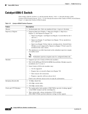
... numbered from 1 (top) to the EOBC channel and the switching bus. • Three replaceable voltage termination (VTT) modules (WS-C6K-VTT-E=) provide reference voltage for bus signals. 1-24 Catalyst 6500 Series Switches Installation Guide OL-5781-04 Table 1-10 lists the specifications of the Catalyst 6506-E switch chassis. Not be installed in standby mode. Figure 1-8 shows the...
... numbered from 1 (top) to the EOBC channel and the switching bus. • Three replaceable voltage termination (VTT) modules (WS-C6K-VTT-E=) provide reference voltage for bus signals. 1-24 Catalyst 6500 Series Switches Installation Guide OL-5781-04 Table 1-10 lists the specifications of the Catalyst 6506-E switch chassis. Not be installed in standby mode. Figure 1-8 shows the...

Installation Guide
Page 50
... are triggered at 40°C (104°F) generating a minor alarm and at 55°C (131°F) generating a major alarm. Catalyst 6506-E Switch Chapter 1 Product Overview Table 1-10 Catalyst 6506-E Switch Specifications Item Environmental Temperature, operating Specification Certified for operation: 32° to 104°F (0° to 40°C) Designed and tested for operation: 32° to...
... are triggered at 40°C (104°F) generating a minor alarm and at 55°C (131°F) generating a major alarm. Catalyst 6506-E Switch Chapter 1 Product Overview Table 1-10 Catalyst 6506-E Switch Specifications Item Environmental Temperature, operating Specification Certified for operation: 32° to 104°F (0° to 40°C) Designed and tested for operation: 32° to...
Installation Guide
Page 51
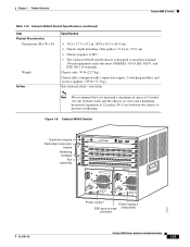
... 300-119 standards. Chapter 1 Product Overview Catalyst 6506-E Switch Table 1-10 Catalyst 6506-E Switch Specifications (continued) Item Physical Characteristics Dimensions (H x W x D) Weight Airflow Specification • 19.2 x 17.5 x 18.2 in. (48.8 x 44.5 x 46.0 cm). • Chassis depth including cable guide is 21.64 in. (55.0 cm). • Chassis requires 12 RU. • The Catalyst 6506-E switch chassis is designed to install in standard...
... 300-119 standards. Chapter 1 Product Overview Catalyst 6506-E Switch Table 1-10 Catalyst 6506-E Switch Specifications (continued) Item Physical Characteristics Dimensions (H x W x D) Weight Airflow Specification • 19.2 x 17.5 x 18.2 in. (48.8 x 44.5 x 46.0 cm). • Chassis depth including cable guide is 21.64 in. (55.0 cm). • Chassis requires 12 RU. • The Catalyst 6506-E switch chassis is designed to install in standard...