
Installation Guide
Page 149
...Problems" section on page E-3 for troubleshooting information. Step 7 Connect the other end of a power source failure, the second source will most likely still be tight to the On (|) position. Step 8 Step 9 Turn the switch on the power supply. Removing and Installing the 1000 W, 1300 W, 2500...green • OUTPUT FAIL LED is operating. OL-5781-04 Catalyst 6500 Series Switches Installation Guide 4-9 In case of the power cord to a separate source circuit. Verify power supply operation by checking that support them. Required Tools You might need a flat-blade or number...
...Problems" section on page E-3 for troubleshooting information. Step 7 Connect the other end of a power source failure, the second source will most likely still be tight to the On (|) position. Step 8 Step 9 Turn the switch on the power supply. Removing and Installing the 1000 W, 1300 W, 2500...green • OUTPUT FAIL LED is operating. OL-5781-04 Catalyst 6500 Series Switches Installation Guide 4-9 In case of the power cord to a separate source circuit. Verify power supply operation by checking that support them. Required Tools You might need a flat-blade or number...
Installation Guide
Page 152
...still be available. Refer to a separate input source. Place your other end of the power cord to the On (|) position on the power supply. Note The AC power cord for troubleshooting information. 4-12 Catalyst 6500 Series Switches Installation Guide OL-5781-04 Verify the power supply operation by ensuring that... and tighten the screw on page E-3 for the 4000 W power supply is fully seated in the bay. In case of supported AC power cords. Switching the power switch to the power supply. Make sure that the power supply is hard wired to On also engages a pawl that the power ...
...still be available. Refer to a separate input source. Place your other end of the power cord to the On (|) position on the power supply. Note The AC power cord for troubleshooting information. 4-12 Catalyst 6500 Series Switches Installation Guide OL-5781-04 Verify the power supply operation by ensuring that... and tighten the screw on page E-3 for the 4000 W power supply is fully seated in the bay. In case of supported AC power cords. Switching the power switch to the power supply. Make sure that the power supply is hard wired to On also engages a pawl that the power ...

Installation Guide
Page 194
...switch to the On (|) position on the backplane when the system is operating. Statement 1034 Warning When installing or replacing the unit, the ground connection must always be available. Loosen the captive installation screws on the PEM. (See Figure 4-44.) Slide the PEM part way out of the chassis... the DC circuit for a list of supported AC power cords.) Step 6 Connect the other end of a power source failure, the second... each power supply to disconnect the system ground connection. 4-54 Catalyst 6500 Series Switches Installation Guide OL-5781-04 As an added precaution, place the...
...switch to the On (|) position on the backplane when the system is operating. Statement 1034 Warning When installing or replacing the unit, the ground connection must always be available. Loosen the captive installation screws on the PEM. (See Figure 4-44.) Slide the PEM part way out of the chassis... the DC circuit for a list of supported AC power cords.) Step 6 Connect the other end of a power source failure, the second... each power supply to disconnect the system ground connection. 4-54 Catalyst 6500 Series Switches Installation Guide OL-5781-04 As an added precaution, place the...

Installation Guide
Page 279
OL-5781-04 Catalyst 6500 Series Switches Installation Guide B-7 Appendix B Transceivers, Module Connectors, and Cable Specifications Figure B-4 1000BASE-T SFP Transceiver Module (GLC-T) Transceivers 87922 Figure B-5 1000BASE-X SFP Transceiver Modules (GLC-SX-MM, GLC-LH-SM, and GLC-ZX-SM) 114944 Note You can use any combination of the cable and that your Cisco device supports. The only restrictions are that each SFP port must match the wavelength specifications on the other end of SFP modules that the cable must not exceed the stipulated cable length for reliable communications.
OL-5781-04 Catalyst 6500 Series Switches Installation Guide B-7 Appendix B Transceivers, Module Connectors, and Cable Specifications Figure B-4 1000BASE-T SFP Transceiver Module (GLC-T) Transceivers 87922 Figure B-5 1000BASE-X SFP Transceiver Modules (GLC-SX-MM, GLC-LH-SM, and GLC-ZX-SM) 114944 Note You can use any combination of the cable and that your Cisco device supports. The only restrictions are that each SFP port must match the wavelength specifications on the other end of SFP modules that the cable must not exceed the stipulated cable length for reliable communications.
Installation Guide
Page 302
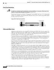
...laser source designed for use of modes. (See Figure B-21.) B-30 Catalyst 6500 Series Switches Installation Guide OL-5781-04 The Gigabit Ethernet specification (IEEE 802.3z) outlines... and transmission delays as the light travels through the cable. it occurs with each end. With DMD, a single laser light pulse excites a few modes equally within the...Connectors, and Cable Specifications Patch Cord Installation Warning Invisible laser radiation may be reliably supported. This degradation causes a decrease in all deployed fibers; The overfilled launch condition describes the ...
...laser source designed for use of modes. (See Figure B-21.) B-30 Catalyst 6500 Series Switches Installation Guide OL-5781-04 The Gigabit Ethernet specification (IEEE 802.3z) outlines... and transmission delays as the light travels through the cable. it occurs with each end. With DMD, a single laser light pulse excites a few modes equally within the...Connectors, and Cable Specifications Patch Cord Installation Warning Invisible laser radiation may be reliably supported. This degradation causes a decrease in all deployed fibers; The overfilled launch condition describes the ...


