
Installation Guide
Page 6
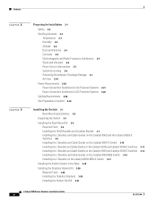
... Installing the L Brackets and Cable Guides on the Catalyst 6506 and Catalyst 6506-E Switches 3-11 Installing the L Brackets and Cable Guides on the Catalyst 6509 and Catalyst 6509-E Switches 3-13 Installing the L Brackets and Cable Guides on the Catalyst 6509-NEB Switch 3-15 Installing the L Brackets on the Catalyst 6509-NEB-A Switch 3-17 Installing the Switch Chassis in the Rack 3-18 Installing the Stabilizer Bracket Kit 3-20...
... Installing the L Brackets and Cable Guides on the Catalyst 6506 and Catalyst 6506-E Switches 3-11 Installing the L Brackets and Cable Guides on the Catalyst 6509 and Catalyst 6509-E Switches 3-13 Installing the L Brackets and Cable Guides on the Catalyst 6509-NEB Switch 3-15 Installing the L Brackets on the Catalyst 6509-NEB-A Switch 3-17 Installing the Switch Chassis in the Rack 3-18 Installing the Stabilizer Bracket Kit 3-20...
Installation Guide
Page 30
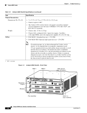
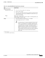
... and the chassis air exhaust. On Catalyst chassis in standard 19-inch equipment racks that you maintain a minimum 6-inch (15 cm) separation between the hot air exhaust on one chassis and the air intake on another chassis. Failure to maintain adequate air space can cause the chassis to overheat and the system to bottom) Catalyst 6500 Series Switches Installation...
... and the chassis air exhaust. On Catalyst chassis in standard 19-inch equipment racks that you maintain a minimum 6-inch (15 cm) separation between the hot air exhaust on one chassis and the air intake on another chassis. Failure to maintain adequate air space can cause the chassis to overheat and the system to bottom) Catalyst 6500 Series Switches Installation...
Installation Guide
Page 35
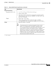
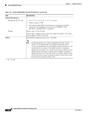
...in. (17.78 x 44.12 x 55.25 cm). • Chassis requires 4 RU1. • The Catalyst 6503-E switch chassis is designed to install in which the airflow is from front to fail. On Catalyst chassis in standard 19-inch equipment racks that you maintain a minimum 6-inch (15 cm) separation between the hot ...air exhaust on one chassis and the air intake on another chassis. OL-5781-04 Catalyst 6500 Series Switches Installation Guide 1-11 You should ...
...in. (17.78 x 44.12 x 55.25 cm). • Chassis requires 4 RU1. • The Catalyst 6503-E switch chassis is designed to install in which the airflow is from front to fail. On Catalyst chassis in standard 19-inch equipment racks that you maintain a minimum 6-inch (15 cm) separation between the hot ...air exhaust on one chassis and the air intake on another chassis. OL-5781-04 Catalyst 6500 Series Switches Installation Guide 1-11 You should ...
Installation Guide
Page 39
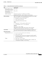
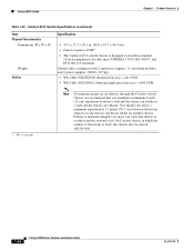
... of 86°F (30°C). • 8.7 x 17.5 x 21.6 in standard 19-inch equipment racks that meet ANSI/EIA 310-D, IEC 60297, and ETS 300-119 standards. • Chassis only: 27 lb (12.25 kg). • Chassis fully configured with Network Equipment Building Systems (NEBS) (Zone 4 per GR-63-Core) in the... 5 dB/octave roll off at each end. 0.5 hours per axis (1.12 Grms). 64 to install in . (22.09 x 44.45 x 54.86 cm). • Chassis requires 5 RU1. • The Catalyst 6504-E switch chassis is designed to 76 dB. International Organization for : -200 to 10,000 feet (-60 to 3000 m) This...
... of 86°F (30°C). • 8.7 x 17.5 x 21.6 in standard 19-inch equipment racks that meet ANSI/EIA 310-D, IEC 60297, and ETS 300-119 standards. • Chassis only: 27 lb (12.25 kg). • Chassis fully configured with Network Equipment Building Systems (NEBS) (Zone 4 per GR-63-Core) in the... 5 dB/octave roll off at each end. 0.5 hours per axis (1.12 Grms). 64 to install in . (22.09 x 44.45 x 54.86 cm). • Chassis requires 5 RU1. • The Catalyst 6504-E switch chassis is designed to 76 dB. International Organization for : -200 to 10,000 feet (-60 to 3000 m) This...

Installation Guide
Page 40
...) between a wall and the chassis air intake or a wall and the chassis air exhaust. Figure 1-5 Catalyst 6504-E Switch-Front View Supervisor Engine OSMs FAN STATUS STATUS STATUS STATUS Slots 1-4 (top to back, the chassis may be placed side-by-side. RU = rack units Note To maintain proper air circulation through the Catalyst switch chassis, we recommend that you maintain...
...) between a wall and the chassis air intake or a wall and the chassis air exhaust. Figure 1-5 Catalyst 6504-E Switch-Front View Supervisor Engine OSMs FAN STATUS STATUS STATUS STATUS Slots 1-4 (top to back, the chassis may be placed side-by-side. RU = rack units Note To maintain proper air circulation through the Catalyst switch chassis, we recommend that you maintain...
Installation Guide
Page 46
... equipment racks that you maintain a minimum 6-inch (15 cm) separation between the hot air exhaust on one chassis and the air intake on another chassis. WS-C6K-6SLOT-FAN (Standard fan tray)-227 CFM. On Catalyst chassis in which the airflow is designed to install in . (55.0 cm). • Chassis requires 12 RU. • The Catalyst 6506 switch chassis...
... equipment racks that you maintain a minimum 6-inch (15 cm) separation between the hot air exhaust on one chassis and the air intake on another chassis. WS-C6K-6SLOT-FAN (Standard fan tray)-227 CFM. On Catalyst chassis in which the airflow is designed to install in . (55.0 cm). • Chassis requires 12 RU. • The Catalyst 6506 switch chassis...
Installation Guide
Page 51
...x 18.2 in. (48.8 x 44.5 x 46.0 cm). • Chassis depth including cable guide is 21.64 in. (55.0 cm). • Chassis requires 12 RU. • The Catalyst 6506-E switch chassis is designed to install in standard 19-inch equipment racks that you maintain a minimum air space of 6 inches (16 cm) between ...walls and the chassis air vents and a minimum horizontal separation of ...
...x 18.2 in. (48.8 x 44.5 x 46.0 cm). • Chassis depth including cable guide is 21.64 in. (55.0 cm). • Chassis requires 12 RU. • The Catalyst 6506-E switch chassis is designed to install in standard 19-inch equipment racks that you maintain a minimum air space of 6 inches (16 cm) between ...walls and the chassis air vents and a minimum horizontal separation of ...
Installation Guide
Page 56
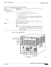
... Catalyst chassis in standard 19-inch equipment racks that you maintain a minimum 6-inch (15 cm) separation between the hot air exhaust on one chassis and the air intake on another chassis. Chassis fully configured with 1 supervisor engine, 8 switching ...should also allow a minimum separation of 12 inches (30.5 cm) between a wall and the chassis air intake or a wall and the chassis air exhaust. Catalyst 6509 Switch Chapter 1 Product Overview Table 1-12 Catalyst 6509 Switch Specifications (continued) Item Physical Characteristics Dimensions (H x W x D) Weight Airflow Specification •...
... Catalyst chassis in standard 19-inch equipment racks that you maintain a minimum 6-inch (15 cm) separation between the hot air exhaust on one chassis and the air intake on another chassis. Chassis fully configured with 1 supervisor engine, 8 switching ...should also allow a minimum separation of 12 inches (30.5 cm) between a wall and the chassis air intake or a wall and the chassis air exhaust. Catalyst 6509 Switch Chapter 1 Product Overview Table 1-12 Catalyst 6509 Switch Specifications (continued) Item Physical Characteristics Dimensions (H x W x D) Weight Airflow Specification •...
Installation Guide
Page 61
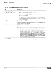
... 60297, and ETS 300-119 standards. On Catalyst chassis in standard 19-inch equipment racks that you maintain a minimum 6-inch (15 cm) separation between the hot air exhaust on one chassis and the air intake on another chassis. WS-C6509-E-FAN-846 CFM 1. Chapter 1 Product Overview Catalyst 6509-E Switch Table 1-14 Catalyst 6509-E Switch Specifications (continued) Item Physical Characteristics Dimensions (H x W x D) Weight...
... 60297, and ETS 300-119 standards. On Catalyst chassis in standard 19-inch equipment racks that you maintain a minimum 6-inch (15 cm) separation between the hot air exhaust on one chassis and the air intake on another chassis. WS-C6509-E-FAN-846 CFM 1. Chapter 1 Product Overview Catalyst 6509-E Switch Table 1-14 Catalyst 6509-E Switch Specifications (continued) Item Physical Characteristics Dimensions (H x W x D) Weight...
Installation Guide
Page 67
... Catalyst chassis in which the airflow is designed to install in . (84.6 x 43.7 x 46.0 cm). • Chassis requires 20 RU1. • The Catalyst 6509-NEB switch chassis is from front to fail. Part of 12 inches (30.5 cm) between a wall and the chassis air intake or a wall and the chassis air exhaust. RU = rack units. 2. OL-5781-04 Catalyst 6500 Series Switches...
... Catalyst chassis in which the airflow is designed to install in . (84.6 x 43.7 x 46.0 cm). • Chassis requires 20 RU1. • The Catalyst 6509-NEB switch chassis is from front to fail. Part of 12 inches (30.5 cm) between a wall and the chassis air intake or a wall and the chassis air exhaust. RU = rack units. 2. OL-5781-04 Catalyst 6500 Series Switches...
Installation Guide
Page 72
FAN-MOD-09 (High-speed fan tray)-760 CFM 1. On Catalyst chassis in standard 19-inch equipment racks that you maintain a minimum 6-inch (15 cm) separation between the hot air exhaust on one chassis and the air intake on another chassis. Catalyst 6509-NEB-A Switch Chapter 1 Product Overview Table 1-18 Catalyst 6509-NEB-A Switch Specifications (continued) Item Physical Characteristics Dimensions (H x W x D) Weight Airflow...
FAN-MOD-09 (High-speed fan tray)-760 CFM 1. On Catalyst chassis in standard 19-inch equipment racks that you maintain a minimum 6-inch (15 cm) separation between the hot air exhaust on one chassis and the air intake on another chassis. Catalyst 6509-NEB-A Switch Chapter 1 Product Overview Table 1-18 Catalyst 6509-NEB-A Switch Specifications (continued) Item Physical Characteristics Dimensions (H x W x D) Weight Airflow...
Installation Guide
Page 78
... intake or a wall and the chassis air exhaust. On Catalyst chassis in standard 19-inch equipment racks that you maintain a minimum 6-inch (15 cm) separation between the hot air exhaust on one chassis and the air intake on another chassis. RU = rack units Note To maintain proper air circulation through the Catalyst switch chassis, we recommend that meet ANSI/EIA...
... intake or a wall and the chassis air exhaust. On Catalyst chassis in standard 19-inch equipment racks that you maintain a minimum 6-inch (15 cm) separation between the hot air exhaust on one chassis and the air intake on another chassis. RU = rack units Note To maintain proper air circulation through the Catalyst switch chassis, we recommend that meet ANSI/EIA...

Installation Guide
Page 81
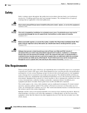
..., poor equipment placement can cause system overtemperature conditions. This chapter describes how to prepare your equipment rack or wiring closet is essential for switch installation and contains these sections: • Safety, page 2-2 • Site Requirements, page 2-2...switch chassis listed in a separate publication, the Catalyst 6000 Series Switch Installation Guide. OL-5781-04 Catalyst 6500 Series Switches Installation Guide 2-1 CH A P T E R 2 Preparing for Installation Note In this publication, the term Catalyst 6500 series refers only to the Catalyst 6500 Series Switch...
..., poor equipment placement can cause system overtemperature conditions. This chapter describes how to prepare your equipment rack or wiring closet is essential for switch installation and contains these sections: • Safety, page 2-2 • Site Requirements, page 2-2...switch chassis listed in a separate publication, the Catalyst 6000 Series Switch Installation Guide. OL-5781-04 Catalyst 6500 Series Switches Installation Guide 2-1 CH A P T E R 2 Preparing for Installation Note In this publication, the term Catalyst 6500 series refers only to the Catalyst 6500 Series Switch...
Installation Guide
Page 82
...chassis panels inaccessable and difficult to protect the system components. The switch environmental monitor can be rack-mounted with the system. However, when mounting a switch in a rack with other equipment, or when placing it on Power over Ethernet (PoE) circuits if interconnections are made aware of your Catalyst 6500 series switch... and Safety Guide. Statement 1072 Site Requirements These sections describe some of the switch chassis. 6-1 Catalyst 6500 Series Switches Installation Guide 2-2 OL-5781-04 To ensure normal operation, maintain ambient airflow. Multiple...
...chassis panels inaccessable and difficult to protect the system components. The switch environmental monitor can be rack-mounted with the system. However, when mounting a switch in a rack with other equipment, or when placing it on Power over Ethernet (PoE) circuits if interconnections are made aware of your Catalyst 6500 series switch... and Safety Guide. Statement 1072 Site Requirements These sections describe some of the switch chassis. 6-1 Catalyst 6500 Series Switches Installation Guide 2-2 OL-5781-04 To ensure normal operation, maintain ambient airflow. Multiple...

Installation Guide
Page 88
...the system ground lug barrel. If you are using an ESD wrist strap that is then safely dissipated to the entire rack. If you are using the ESD wrist strap that is equipped with the FRUs, open the package and remove the...ESD wrist strap. We recommend that you touch the clip to an unpainted rack rail so that the spring clip jaws close behind the lug screw head. Catalyst 6500 Series Switches Installation Guide 2-8 OL-5781-04 Attach either the spring clip or the ...spring clip jaws do not open , position the spring clip to a bare metal spot (unpainted surface) on the rack.
...the system ground lug barrel. If you are using an ESD wrist strap that is then safely dissipated to the entire rack. If you are using the ESD wrist strap that is equipped with the FRUs, open the package and remove the...ESD wrist strap. We recommend that you touch the clip to an unpainted rack rail so that the spring clip jaws close behind the lug screw head. Catalyst 6500 Series Switches Installation Guide 2-8 OL-5781-04 Attach either the spring clip or the ...spring clip jaws do not open , position the spring clip to a bare metal spot (unpainted surface) on the rack.

Installation Guide
Page 90
... The system fan assembly provides cooling air for the Catalyst 6500 series switches. In situations where the switch chassis are installed in adjacent racks, you should allow the chassis temperature to stabilize (approximately 2 hours). Measure the ambient air temperature at the chassis air intake grill and at the chassis air exhaust grill by positioning an external temperature probe...
... The system fan assembly provides cooling air for the Catalyst 6500 series switches. In situations where the switch chassis are installed in adjacent racks, you should allow the chassis temperature to stabilize (approximately 2 hours). Measure the ambient air temperature at the chassis air intake grill and at the chassis air exhaust grill by positioning an external temperature probe...

Installation Guide
Page 91
...) - WS-C6K-13SLT-FAN2 (high speed) 1. Your Catalyst 6500 series switches currently installed in the rack, the additional heat generated might meet ambient air temperature and air flow requirements now. Individual fans cannot be replaced. Catalyst 6506 WS-C6K-6SLOT-FAN WS-6506-E-FAN WS-C6K-6SLOT... Catalyst 6509 WS-C6K-9SLOT-FAN WS-6509-E-FAN WS-C6K-9SLOT-FAN2 (high speed) Catalyst 6509-E WS-6509-E-FAN WS-C6K-9SLOT-FAN WS-C6K-9SLOT-FAN2 (high speed) Catalyst 6509-NEB WS-C6509-NEB-FAN - However, if you add more chassis to the rack or you add more modules to a chassis in...
...) - WS-C6K-13SLT-FAN2 (high speed) 1. Your Catalyst 6500 series switches currently installed in the rack, the additional heat generated might meet ambient air temperature and air flow requirements now. Individual fans cannot be replaced. Catalyst 6506 WS-C6K-6SLOT-FAN WS-6506-E-FAN WS-C6K-6SLOT... Catalyst 6509 WS-C6K-9SLOT-FAN WS-6509-E-FAN WS-C6K-9SLOT-FAN2 (high speed) Catalyst 6509-E WS-6509-E-FAN WS-C6K-9SLOT-FAN WS-C6K-9SLOT-FAN2 (high speed) Catalyst 6509-NEB WS-C6509-NEB-FAN - However, if you add more chassis to the rack or you add more modules to a chassis in...
Installation Guide
Page 92
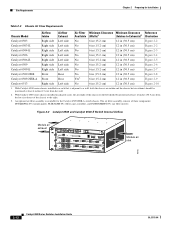
...RX TX PORT4 Module air inlet 63182 2-12 Catalyst 6500 Series Switches Installation Guide OL-5781-04 With Catalyst 6500 series chassis installed in adjacent racks, the air intake of the chassis on the left should be positioned at least... rack that is available for Installation Table 2-3 Chassis Air Flow Requirements Chassis Model Airflow Intake Airflow Exhaust Air Filter Minimum Clearance Minimum Clearance Reference Available (Walls)1 (Intakes to the right. 3. Site Requirements Chapter 2 Preparing for the Catalyst 6509-NEB-A switch chassis. With Catalyst 6500 series chassis ...
...RX TX PORT4 Module air inlet 63182 2-12 Catalyst 6500 Series Switches Installation Guide OL-5781-04 With Catalyst 6500 series chassis installed in adjacent racks, the air intake of the chassis on the left should be positioned at least... rack that is available for Installation Table 2-3 Chassis Air Flow Requirements Chassis Model Airflow Intake Airflow Exhaust Air Filter Minimum Clearance Minimum Clearance Reference Available (Walls)1 (Intakes to the right. 3. Site Requirements Chapter 2 Preparing for the Catalyst 6509-NEB-A switch chassis. With Catalyst 6500 series chassis ...
Installation Guide
Page 105
... in the following sections in the order listed: • Unpacking the Switch, page 3-2 • Installing the Rack-Mount Kit, page 3-3 • Installing the Switch Chassis in the Rack, page 3-14 • Installing the Stabilizer Kit, page 3-16 • Installing the Cable Management System (Catalyst 6509-NEB-A Switch Only), page 3-18 • Establishing the System Ground, page 3-22 •...
... in the following sections in the order listed: • Unpacking the Switch, page 3-2 • Installing the Rack-Mount Kit, page 3-3 • Installing the Switch Chassis in the Rack, page 3-14 • Installing the Stabilizer Kit, page 3-16 • Installing the Cable Management System (Catalyst 6509-NEB-A Switch Only), page 3-18 • Establishing the System Ground, page 3-22 •...

Installation Guide
Page 106
Statement 94 Note If you are installing a free-standing (not rack-mounted) Catalyst 6509-NEB or Catalyst 6513 switch, you received all listed equipment, which is open, or both. Unpacking the Switch Tip Do not discard the shipping container when you could be installed and maintained by service personnel as network interface cables, transceivers, or special connectors...
Statement 94 Note If you are installing a free-standing (not rack-mounted) Catalyst 6509-NEB or Catalyst 6513 switch, you received all listed equipment, which is open, or both. Unpacking the Switch Tip Do not discard the shipping container when you could be installed and maintained by service personnel as network interface cables, transceivers, or special connectors...