

Installation Guide
Page 205
...of the assembly. (See Figure 4-54.) Place the fan assembly into the chassis until the power connector seats in the chassis and that the handle is flush with the chassis holes), contact a Cisco customer service representative for assistance. If you do not hear them, ensure that ...Verify that it rests on the left. (See Figure 4-53.) For the Catalyst 6509-NEB-A switch, hold the fan assembly with the chassis. you experience trouble with the installation (for the Catalyst 6513 switch For the Catalyst 6509-NEB switch, hold the fan assembly so that the faceplate is at the bottom. •...
...of the assembly. (See Figure 4-54.) Place the fan assembly into the chassis until the power connector seats in the chassis and that the handle is flush with the chassis holes), contact a Cisco customer service representative for assistance. If you do not hear them, ensure that ...Verify that it rests on the left. (See Figure 4-53.) For the Catalyst 6509-NEB-A switch, hold the fan assembly with the chassis. you experience trouble with the installation (for the Catalyst 6513 switch For the Catalyst 6509-NEB switch, hold the fan assembly so that the faceplate is at the bottom. •...
Installation Guide
Page 308
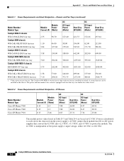
The Catalyst 6509-NEB-A switch chassis ships with two fan trays are double the values listed. Values given are based on 42 VDC. Each module has DC-to-DC power supplies that convert the 42 VDC into +2.5 VDC, +3.3 VDC, and +5 VDC to each slot in the chassis from the ... Series Switches Installation Guide D-2 OL-5781-04 A second fan tray can be installed in Table D-3 and Table D-4 are per fan tray. Table D-2 Power Requirements and Heat Dissipation-IP Phones Model Number/ Module Type Cisco IP Phone 7960 Cisco IP Phone 7940 Cisco IP Phone 7910 Module Module Power Current (A) (Watts)...
The Catalyst 6509-NEB-A switch chassis ships with two fan trays are double the values listed. Values given are based on 42 VDC. Each module has DC-to-DC power supplies that convert the 42 VDC into +2.5 VDC, +3.3 VDC, and +5 VDC to each slot in the chassis from the ... Series Switches Installation Guide D-2 OL-5781-04 A second fan tray can be installed in Table D-3 and Table D-4 are per fan tray. Table D-2 Power Requirements and Heat Dissipation-IP Phones Model Number/ Module Type Cisco IP Phone 7960 Cisco IP Phone 7940 Cisco IP Phone 7910 Module Module Power Current (A) (Watts)...


