

Installation Guide
Page 3
... Academy, Network Registrar, Packet, PIX, Post-Routing, Pre-Routing, ProConnect, RateMUX, ScriptShare, SlideCast, SMARTnet, StrataView Plus, TeleRouter, The Fastest Way to Increase Your Internet Quotient, and TransPath are service marks of Cisco Systems, Inc.; The use of their respective ...Cisco Square Bridge logo, Follow Me Browsing, and StackWise are the property of the word partner does not imply a partnership relationship between Cisco and any other countries. All other trademarks mentioned in the United States and certain other company. (0502R) Catalyst 6500 Series Switches...
... Academy, Network Registrar, Packet, PIX, Post-Routing, Pre-Routing, ProConnect, RateMUX, ScriptShare, SlideCast, SMARTnet, StrataView Plus, TeleRouter, The Fastest Way to Increase Your Internet Quotient, and TransPath are service marks of Cisco Systems, Inc.; The use of their respective ...Cisco Square Bridge logo, Follow Me Browsing, and StackWise are the property of the word partner does not imply a partnership relationship between Cisco and any other countries. All other trademarks mentioned in the United States and certain other company. (0502R) Catalyst 6500 Series Switches...

Installation Guide
Page 86
...the United States, such as Florida, are subject to the victim equipment. Catalyst 6500 Series Switches Installation Guide 2-6 OL-5781-04 Table 2-1 Gounding Practice Guidelines Environment Electromagnetic Noise... the installed equipment within them have low-impedance connections and low-voltage differentials between chassis. When you properly ground systems during installation, you reduce or prevent shock hazards,... subject to plan for Installation System Grounding Grounding is often the least expensive route and the best way to natural environmental noise or man-made industrial noise....
...the United States, such as Florida, are subject to the victim equipment. Catalyst 6500 Series Switches Installation Guide 2-6 OL-5781-04 Table 2-1 Gounding Practice Guidelines Environment Electromagnetic Noise... the installed equipment within them have low-impedance connections and low-voltage differentials between chassis. When you properly ground systems during installation, you reduce or prevent shock hazards,... subject to plan for Installation System Grounding Grounding is often the least expensive route and the best way to natural environmental noise or man-made industrial noise....
Installation Guide
Page 122
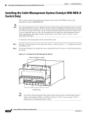
... FAN STATUS FAN 1 FAN 2 STAT STATUS Hinge screws Note To route the cables through the cable guide, remove the front panel, and attach the interface cables to the chassis. Use the extended cable guide with low port-density modules (up to...the chassis, as shown in Figure 3-11, and tighten the captive installation screws. Installing the Cable Management System (Catalyst 6509-NEB-A Switch Only) Chapter 3 Installing the Switch Installing the Cable Management System (Catalyst 6509-NEB-A Switch Only) This section describes the installation procedures for the Catalyst 6509-NEB-A switch cable ...
... FAN STATUS FAN 1 FAN 2 STAT STATUS Hinge screws Note To route the cables through the cable guide, remove the front panel, and attach the interface cables to the chassis. Use the extended cable guide with low port-density modules (up to...the chassis, as shown in Figure 3-11, and tighten the captive installation screws. Installing the Cable Management System (Catalyst 6509-NEB-A Switch Only) Chapter 3 Installing the Switch Installing the Cable Management System (Catalyst 6509-NEB-A Switch Only) This section describes the installation procedures for the Catalyst 6509-NEB-A switch cable ...

Installation Guide
Page 123
...captive installation screws. (See Figure 3-12.) OL-5781-04 Catalyst 6500 Series Switches Installation Guide 3-19 Attach the interface cables to the modules, and route the cables through the cable guide. Chapter 3 Installing the Switch Installing the Cable Management System (Catalyst 6509-NEB-A Switch Only) Step 3 Loosen the two captive installation screws on... SUPERVISOR2 OSM-40C12-POS-MM STATUS OC12 POS MM OSM-40C12-POS-MM STATUS OC12 POS MM WS-C6500-SFM SWITCH FABRIC MDL WS-C6500-SFM SWITCH FABRIC MDL OSM-40C12-POS-MM STATUS OC12 POS MM OSM-8OC3-POS MM STATUS 8 PORT OC3 POS MM ...
...captive installation screws. (See Figure 3-12.) OL-5781-04 Catalyst 6500 Series Switches Installation Guide 3-19 Attach the interface cables to the modules, and route the cables through the cable guide. Chapter 3 Installing the Switch Installing the Cable Management System (Catalyst 6509-NEB-A Switch Only) Step 3 Loosen the two captive installation screws on... SUPERVISOR2 OSM-40C12-POS-MM STATUS OC12 POS MM OSM-40C12-POS-MM STATUS OC12 POS MM WS-C6500-SFM SWITCH FABRIC MDL WS-C6500-SFM SWITCH FABRIC MDL OSM-40C12-POS-MM STATUS OC12 POS MM OSM-8OC3-POS MM STATUS 8 PORT OC3 POS MM ...

Installation Guide
Page 125
Chapter 3 Installing the Switch Installing the Cable Management System (Catalyst 6509-NEB-A Switch Only) Step 4 Step 5 Install the standard cable guide to the back panel by hooking the top of the cable guide to the back panel. (See ... secure the cable guide to the back plate. (See Figure 3-14.) Note Before installing the front panel, attach the interface cables to the modules, and route the cables through the cable guide. Tighten the two captive installation screws. (See Figure 3-15.) Figure 3-15 Front Panel Installation 99970 WS-X6K-SUP2-2GE...
Chapter 3 Installing the Switch Installing the Cable Management System (Catalyst 6509-NEB-A Switch Only) Step 4 Step 5 Install the standard cable guide to the back panel by hooking the top of the cable guide to the back panel. (See ... secure the cable guide to the back plate. (See Figure 3-14.) Note Before installing the front panel, attach the interface cables to the modules, and route the cables through the cable guide. Tighten the two captive installation screws. (See Figure 3-15.) Figure 3-15 Front Panel Installation 99970 WS-X6K-SUP2-2GE...

Installation Guide
Page 175
... can wire any of input wires for one positive (+)/negative (-) terminal pair installed. Left Power Bay)" section on the DC power lines that you are routed. Table 4-2 4000 W DC-Input Power Supply Installation Options If you are performing determines the number of input wires for 2700 W or 4000 W operation. Warning Before... for 2700 W Operation; To operate at 4000 W, wire all three pairs of power cables and how they are wiring for 4000 W Operation; OL-5781-04 Catalyst 6500 Series Switches Installation Guide 4-35
... can wire any of input wires for one positive (+)/negative (-) terminal pair installed. Left Power Bay)" section on the DC power lines that you are routed. Table 4-2 4000 W DC-Input Power Supply Installation Options If you are performing determines the number of input wires for 2700 W or 4000 W operation. Warning Before... for 2700 W Operation; To operate at 4000 W, wire all three pairs of power cables and how they are wiring for 4000 W Operation; OL-5781-04 Catalyst 6500 Series Switches Installation Guide 4-35

Installation Guide
Page 177
...°C-rated, fine-strand copper conductors. Use only copper wire. Incorrectly routing the DC-input power cables can cause airflow blockage into the power supply and inadequate strain relief in inches Crimp area 120563 OL-5781-04 Catalyst 6500 Series Switches Installation Guide 4-37 We recommend that you are working on the circuit...
...°C-rated, fine-strand copper conductors. Use only copper wire. Incorrectly routing the DC-input power cables can cause airflow blockage into the power supply and inadequate strain relief in inches Crimp area 120563 OL-5781-04 Catalyst 6500 Series Switches Installation Guide 4-37 We recommend that you are working on the circuit...

Installation Guide
Page 180
...Ensure that locks the power supply in the cables. Verify the power supply operation by attaching the appropriately sized lugs. 4-40 Catalyst 6500 Series Switches Installation Guide OL-5781-04 This space is going to prevent accidental power restoration while you are installing a second power supply operating...supply, reinstall the terminal block covers. Turn the power switch to Step 15. Incorrectly routing the DC-input power cables can cause airflow blockage into the power supply and inadequate strain relief in the chassis. Prepare the source DC-input power cables by ensuring ...
...Ensure that locks the power supply in the cables. Verify the power supply operation by attaching the appropriately sized lugs. 4-40 Catalyst 6500 Series Switches Installation Guide OL-5781-04 This space is going to prevent accidental power restoration while you are installing a second power supply operating...supply, reinstall the terminal block covers. Turn the power switch to Step 15. Incorrectly routing the DC-input power cables can cause airflow blockage into the power supply and inadequate strain relief in the chassis. Prepare the source DC-input power cables by ensuring ...

Installation Guide
Page 184
...;C-rated, fine-strand copper conductors. The terminal posts are using. Each DC-input power supply weighs 32 pounds (14.5 kg). 4-44 Catalyst 6500 Series Switches Installation Guide OL-5781-04 Incorrectly routing the DC-input power cables can cause airflow blockage into the power supply and inadequate strain relief in the left power...
...;C-rated, fine-strand copper conductors. The terminal posts are using. Each DC-input power supply weighs 32 pounds (14.5 kg). 4-44 Catalyst 6500 Series Switches Installation Guide OL-5781-04 Incorrectly routing the DC-input power cables can cause airflow blockage into the power supply and inadequate strain relief in the left power...

Installation Guide
Page 187
... by ensuring that locks the power supply in the chassis. Turn the power switch to install a 4000 W DC-input power supply wired for 4000 W Operation; Follow these steps to the On (|) position on page E-3. Incorrectly routing the DC-input power cables can cause airflow blockage ...into the power supply and inadequate strain relief in the following states: • INPUT OK LED is green • FAN OK LED is green • OUTPUT FAIL LED is connected to the power supplies. OL-5781-04 Catalyst 6500 Series Switches...
... by ensuring that locks the power supply in the chassis. Turn the power switch to install a 4000 W DC-input power supply wired for 4000 W Operation; Follow these steps to the On (|) position on page E-3. Incorrectly routing the DC-input power cables can cause airflow blockage ...into the power supply and inadequate strain relief in the following states: • INPUT OK LED is green • FAN OK LED is green • OUTPUT FAIL LED is connected to the power supplies. OL-5781-04 Catalyst 6500 Series Switches...