
Installation Guide
Page 7
...Catalyst 6509-NEB-A Switch Only) 3-23 Replacing the Cable Guide 3-25 Establishing the System Ground 3-27 Required Tools and Parts 3-28 Connecting the System Ground 3-29 Installing the Power Supplies in the Switch Chassis 3-34 Attaching the Interface Cables 3-34 Connecting the Supervisor Engine Console Port 3-34 Connecting the Supervisor Engine Uplink Ports 3-36 Verifying Switch Chassis...Installing the Fan Assembly 4-65 Checking the Installation 4-65 Installing the Air Filter Assembly on a Catalyst 6509-NEB-A Switch (Optional) 4-66 OL-5781-04 Catalyst 6500 Series Switches Installation Guide vii
...Catalyst 6509-NEB-A Switch Only) 3-23 Replacing the Cable Guide 3-25 Establishing the System Ground 3-27 Required Tools and Parts 3-28 Connecting the System Ground 3-29 Installing the Power Supplies in the Switch Chassis 3-34 Attaching the Interface Cables 3-34 Connecting the Supervisor Engine Console Port 3-34 Connecting the Supervisor Engine Uplink Ports 3-36 Verifying Switch Chassis...Installing the Fan Assembly 4-65 Checking the Installation 4-65 Installing the Air Filter Assembly on a Catalyst 6509-NEB-A Switch (Optional) 4-66 OL-5781-04 Catalyst 6500 Series Switches Installation Guide vii
Installation Guide
Page 25
... to Supervisor Engine 1, Supervisor Engine 2, Supervisor Engine 32, and Supervisor Engine 720. OL-5781-04 Catalyst 6500 Series Switches Installation Guide 1-1 Product Overview CH A P T E R 1 This chapter describes the Catalyst 6500 series switches and contains these sections: • Catalyst 6503 Switch, page 1-2 • Catalyst 6503-E Switch, page 1-8 • Catalyst 6504-E Switch, page 1-13 • Catalyst 6506 Switch, page 1-18 • Catalyst 6506-E Switch, page 1-24 • Catalyst 6509 Switch, page 1-28 • Catalyst 6509-E Switch, page 1-34 • Catalyst 6509-NEB Switch...
... to Supervisor Engine 1, Supervisor Engine 2, Supervisor Engine 32, and Supervisor Engine 720. OL-5781-04 Catalyst 6500 Series Switches Installation Guide 1-1 Product Overview CH A P T E R 1 This chapter describes the Catalyst 6500 series switches and contains these sections: • Catalyst 6503 Switch, page 1-2 • Catalyst 6503-E Switch, page 1-8 • Catalyst 6504-E Switch, page 1-13 • Catalyst 6506 Switch, page 1-18 • Catalyst 6506-E Switch, page 1-24 • Catalyst 6509 Switch, page 1-28 • Catalyst 6509-E Switch, page 1-34 • Catalyst 6509-NEB Switch...
Installation Guide
Page 26
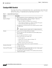
... 3 (bottom). • Supports Supervisor Engine 1, Supervisor Engine 2, Supervisor Engine 32, and Supervisor Engine 720. - Using a Supervisor Engine 32 or a Supervisor Engine 720 requires that you install the optional high-speed fan tray. • The uplink ports are installed in standby mode. Figure 1-1 shows the front view and Figure 1-2 shows the rear view of the Catalyst 6503 switch chassis. Table 1-1 lists the features of the Catalyst 6503 switch chassis.
... 3 (bottom). • Supports Supervisor Engine 1, Supervisor Engine 2, Supervisor Engine 32, and Supervisor Engine 720. - Using a Supervisor Engine 32 or a Supervisor Engine 720 requires that you install the optional high-speed fan tray. • The uplink ports are installed in standby mode. Figure 1-1 shows the front view and Figure 1-2 shows the rear view of the Catalyst 6503 switch chassis. Table 1-1 lists the features of the Catalyst 6503 switch chassis.

Installation Guide
Page 27
... individual fans. Supports Supervisor Engine 1 and Supervisor Engine 2. OL-5781-04 Catalyst 6500 Series Switches Installation Guide 1-3 does not support Supervisor Engine 32 or Supervisor Engine 720. - Required for Supervisor Engine 32 and Supervisor Engine 720. The individual fans are supported: - Green-Fan tray is not supported in the Catalyst 6503 chassis. • Fan tray STATUS LED - Chapter 1 Product Overview Catalyst 6503 Switch Table 1-1 Catalyst 6503 Switch Features (continued) Feature...
... individual fans. Supports Supervisor Engine 1 and Supervisor Engine 2. OL-5781-04 Catalyst 6500 Series Switches Installation Guide 1-3 does not support Supervisor Engine 32 or Supervisor Engine 720. - Required for Supervisor Engine 32 and Supervisor Engine 720. The individual fans are supported: - Green-Fan tray is not supported in the Catalyst 6503 chassis. • Fan tray STATUS LED - Chapter 1 Product Overview Catalyst 6503 Switch Table 1-1 Catalyst 6503 Switch Features (continued) Feature...
Installation Guide
Page 30
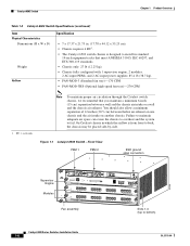
... units Note To maintain proper air circulation through the Catalyst switch chassis, we recommend that meet ANSI/EIA 310-D, IEC 60297, and ETS 300-119 standards. • Chassis only: 27 lb (12.25 kg). • Chassis fully configured with 1 supervisor engine, 2 modules, 2 AC-input PEMs, and 2... 12 inches (30.5 cm) between a wall and the chassis air intake or a wall and the chassis air exhaust. Figure 1-1 Catalyst 6503 Switch-Front View PEM 1 PEM 2 ESD ground strap connection 91239 Supervisor Engine Modules WS-X6K-SUP2-2GE STATUS SYSTEMCONSOLPEWR MGRMETSET SUPERVISOR2 CONSOLE CONSOLE...
... units Note To maintain proper air circulation through the Catalyst switch chassis, we recommend that meet ANSI/EIA 310-D, IEC 60297, and ETS 300-119 standards. • Chassis only: 27 lb (12.25 kg). • Chassis fully configured with 1 supervisor engine, 2 modules, 2 AC-input PEMs, and 2... 12 inches (30.5 cm) between a wall and the chassis air intake or a wall and the chassis air exhaust. Figure 1-1 Catalyst 6503 Switch-Front View PEM 1 PEM 2 ESD ground strap connection 91239 Supervisor Engine Modules WS-X6K-SUP2-2GE STATUS SYSTEMCONSOLPEWR MGRMETSET SUPERVISOR2 CONSOLE CONSOLE...
Installation Guide
Page 32
.... • Does not support the WS-C6500-SFM and WS-X6500-SFM2 Switch Fabric Modules. • Some Catalyst 6500 series modules may: - Supervisor engines are installed in standby mode. Catalyst 6503-E Switch Chapter 1 Product Overview Catalyst 6503-E Switch The Catalyst 6503-E switch is a 3-slot horizontal chassis. Table 1-3 Catalyst 6503-E Switch Features Feature Chassis Supervisor Engine Description • Three horizontal slots. Slots are fully functional on the...
.... • Does not support the WS-C6500-SFM and WS-X6500-SFM2 Switch Fabric Modules. • Some Catalyst 6500 series modules may: - Supervisor engines are installed in standby mode. Catalyst 6503-E Switch Chapter 1 Product Overview Catalyst 6503-E Switch The Catalyst 6503-E switch is a 3-slot horizontal chassis. Table 1-3 Catalyst 6503-E Switch Features Feature Chassis Supervisor Engine Description • Three horizontal slots. Slots are fully functional on the...
Installation Guide
Page 35
...-by-side. RU = rack units Note To maintain proper air circulation through the Catalyst switch chassis, we recommend that meet ANSI/EIA 310-D, IEC 60297, and ETS 300-119 standards. • Chassis only: 33 lb (15 kg). • Chassis fully configured with 1 supervisor engine, 2 modules, 2 AC-input PEMs, and 2 AC-input power supplies: 85.4 lb (38.7 kg...
...-by-side. RU = rack units Note To maintain proper air circulation through the Catalyst switch chassis, we recommend that meet ANSI/EIA 310-D, IEC 60297, and ETS 300-119 standards. • Chassis only: 33 lb (15 kg). • Chassis fully configured with 1 supervisor engine, 2 modules, 2 AC-input PEMs, and 2 AC-input power supplies: 85.4 lb (38.7 kg...
Installation Guide
Page 36
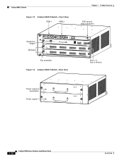
Catalyst 6503-E Switch Figure 1-3 Catalyst 6503-E Switch-Front View PEM 1 PEM 2 Chapter 1 Product Overview ESD ground strap connection 91239 Supervisor Engine Modules WS-X6K-SUP2-2GE STATUS SYSTEMCONSOLPEWR MGRMETSET SUPERVISOR2 CONSOLE CONSOLE PORT MODE WS-X6516-GE-T X 16 PORT 1000 BASE-T GE WS-X6516-GE-T X 16 ...
Catalyst 6503-E Switch Figure 1-3 Catalyst 6503-E Switch-Front View PEM 1 PEM 2 Chapter 1 Product Overview ESD ground strap connection 91239 Supervisor Engine Modules WS-X6K-SUP2-2GE STATUS SYSTEMCONSOLPEWR MGRMETSET SUPERVISOR2 CONSOLE CONSOLE PORT MODE WS-X6516-GE-T X 16 PORT 1000 BASE-T GE WS-X6516-GE-T X 16 ...
Installation Guide
Page 37
...; Supports Supervisor Engine 32 and Supervisor Engine 720. - Supervisor engines are installed in standby mode. Modules Backplane Bandwidth Clock and VTT module Note Redundant supervisor engines must be supported - Have chassis slot restrictions - Table 1-6 lists the specifications of the Catalyst 6504-E switch. OL-5781-04 Catalyst 6500 Series Switches Installation Guide 1-13 Chapter 1 Product Overview Catalyst 6504-E Switch Catalyst 6504-E Switch The Catalyst 6504-E switch is a 4-slot horizontal chassis. Require...
...; Supports Supervisor Engine 32 and Supervisor Engine 720. - Supervisor engines are installed in standby mode. Modules Backplane Bandwidth Clock and VTT module Note Redundant supervisor engines must be supported - Have chassis slot restrictions - Table 1-6 lists the specifications of the Catalyst 6504-E switch. OL-5781-04 Catalyst 6500 Series Switches Installation Guide 1-13 Chapter 1 Product Overview Catalyst 6504-E Switch Catalyst 6504-E Switch The Catalyst 6504-E switch is a 4-slot horizontal chassis. Require...
Installation Guide
Page 39
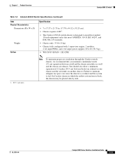
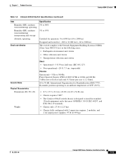
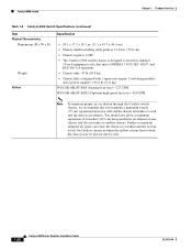
...and ETS 300-119 standards. • Chassis only: 27 lb (12.25 kg). • Chassis fully configured with 2 supervisor engines, 2 modules, and 2 AC-input power supplies: 97 lb (43.99 kg). Chapter 1 Product Overview Catalyst 6504-E Switch Table 1-6 Catalyst 6504-E Switch Specifications (continued) Item Humidity (RH), ...;C). • 8.7 x 17.5 x 21.6 in. (22.09 x 44.45 x 54.86 cm). • Chassis requires 5 RU1. • The Catalyst 6504-E switch chassis is designed to install in the following areas: • Earthquake environment and criteria • Office vibration and criteria •...
...and ETS 300-119 standards. • Chassis only: 27 lb (12.25 kg). • Chassis fully configured with 2 supervisor engines, 2 modules, and 2 AC-input power supplies: 97 lb (43.99 kg). Chapter 1 Product Overview Catalyst 6504-E Switch Table 1-6 Catalyst 6504-E Switch Specifications (continued) Item Humidity (RH), ...;C). • 8.7 x 17.5 x 21.6 in. (22.09 x 44.45 x 54.86 cm). • Chassis requires 5 RU1. • The Catalyst 6504-E switch chassis is designed to install in the following areas: • Earthquake environment and criteria • Office vibration and criteria •...

Installation Guide
Page 40
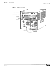
... CFM 1. RU = rack units Note To maintain proper air circulation through the Catalyst switch chassis, we recommend that you maintain a minimum 6-inch (15 cm) separation between the hot air exhaust on one chassis and the air intake on another chassis. Figure 1-5 Catalyst 6504-E Switch-Front View Supervisor Engine OSMs FAN STATUS STATUS STATUS STATUS Slots 1-4 (top to bottom) 126559...
... CFM 1. RU = rack units Note To maintain proper air circulation through the Catalyst switch chassis, we recommend that you maintain a minimum 6-inch (15 cm) separation between the hot air exhaust on one chassis and the air intake on another chassis. Figure 1-5 Catalyst 6504-E Switch-Front View Supervisor Engine OSMs FAN STATUS STATUS STATUS STATUS Slots 1-4 (top to bottom) 126559...
Installation Guide
Page 42
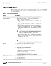
... 6. - Require that you install a Supervisor Engine 720 - Table 1-7 lists the features of the Catalyst 6506 switch chassis. Slots are installed in the chassis to 6 (bottom). • Supports Supervisor Engine 1, Supervisor Engine 2, Supervisor Engine 32, and Supervisor Engine 720. - Supervisor Engine 720 has built-in slot 1 or slot 2. - Supervisor Engine 32 and Supervisor Engine 720 are numbered from either 120 VAC or 220 VAC. - Supervisor Engine 32 and Supervisor Engine 720 require that you install...
... 6. - Require that you install a Supervisor Engine 720 - Table 1-7 lists the features of the Catalyst 6506 switch chassis. Slots are installed in the chassis to 6 (bottom). • Supports Supervisor Engine 1, Supervisor Engine 2, Supervisor Engine 32, and Supervisor Engine 720. - Supervisor Engine 720 has built-in slot 1 or slot 2. - Supervisor Engine 32 and Supervisor Engine 720 are numbered from either 120 VAC or 220 VAC. - Supervisor Engine 32 and Supervisor Engine 720 require that you install...
Installation Guide
Page 43
... the chassis to the EOBC channel and the switching bus. • Three replaceable voltage termination (VTT) modules (WS-C6K-VTT=) provide reference voltage for Supervisor Engine 32 and Supervisor Engine 720. does not support Supervisor Engine 32 or Supervisor Engine 720. - OL-5781-04 Catalyst 6500 Series Switches Installation Guide 1-19 WS-C6K-6SLOT-FAN (Standard fan tray-227 CFM). Supports Supervisor Engine 1 and Supervisor Engine...
... the chassis to the EOBC channel and the switching bus. • Three replaceable voltage termination (VTT) modules (WS-C6K-VTT=) provide reference voltage for Supervisor Engine 32 and Supervisor Engine 720. does not support Supervisor Engine 32 or Supervisor Engine 720. - OL-5781-04 Catalyst 6500 Series Switches Installation Guide 1-19 WS-C6K-6SLOT-FAN (Standard fan tray-227 CFM). Supports Supervisor Engine 1 and Supervisor Engine...
Installation Guide
Page 44
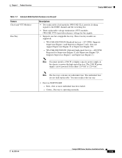
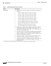
... power supply bay. • You must install a 2500 W or higher capacity power supply when using the Supervisor Engine 32 or the Supervisor Engine 720 and the high-speed fan tray. 1. WS-CDC-2500W (2500 W DC-input power supply). - Source...Power supplies can also be configured in a Catalyst 6506 switch chassis, the 6000 W power supply has a maximum output of different wattage ratings. WS-CAC-2500W (2500 W AC-input power supply). - Catalyst 6506 Switch Chapter 1 Product Overview Table 1-7 Catalyst 6506 Switch Features (continued) Feature Descriptions Power Supply •...
... power supply bay. • You must install a 2500 W or higher capacity power supply when using the Supervisor Engine 32 or the Supervisor Engine 720 and the high-speed fan tray. 1. WS-CDC-2500W (2500 W DC-input power supply). - Source...Power supplies can also be configured in a Catalyst 6506 switch chassis, the 6000 W power supply has a maximum output of different wattage ratings. WS-CAC-2500W (2500 W AC-input power supply). - Catalyst 6506 Switch Chapter 1 Product Overview Table 1-7 Catalyst 6506 Switch Features (continued) Feature Descriptions Power Supply •...
Installation Guide
Page 46
Note To maintain proper air circulation through the Catalyst switch chassis, we recommend that meet ANSI/EIA 310-D, IEC 60297, and ETS 300-119 standards. • Chassis only: 45 lb (20.4 kg). • Chassis fully configured with 1 supervisor engine, 5 switching modules, and 2 power supplies: 156.6 lb (71.0 kg). You should also allow a minimum separation of 12 inches (30.5 cm...
Note To maintain proper air circulation through the Catalyst switch chassis, we recommend that meet ANSI/EIA 310-D, IEC 60297, and ETS 300-119 standards. • Chassis only: 45 lb (20.4 kg). • Chassis fully configured with 1 supervisor engine, 5 switching modules, and 2 power supplies: 156.6 lb (71.0 kg). You should also allow a minimum separation of 12 inches (30.5 cm...
Installation Guide
Page 47
...Catalyst 6506 Switch Supervisor engine Redundant supervisor engine Switching modules Fan assembly 1 2 3 4 FAN STATUS 5 6 WS-X6K-SUP2-2GE STATUS SYSTEMCONSOLPEWR MGRMETSET SUPERVISOR2 CONSOLE WS-X6K-SUP2-2GE STATUS SYSTEMCONSOLPEWR MGRMETSET SUPERVISOR2 CONSOLE CONSOLE PORT MODE CONSOLE PORT MODE WS-X6408 1 2 STATUS 8 PORT GIGABIT ETHERNET WS-X6408 1 2 8 PORT GIGABIT ETHERNET PCMCIA EJECT PCMCIA 3 EJECT 4 3 4 Switch Load 100% 1% Switch...ESD ground strap (redundant) connector Catalyst 6506 Switch 18224 OL-5781-04 Catalyst 6500 Series Switches Installation Guide 1-23
...Catalyst 6506 Switch Supervisor engine Redundant supervisor engine Switching modules Fan assembly 1 2 3 4 FAN STATUS 5 6 WS-X6K-SUP2-2GE STATUS SYSTEMCONSOLPEWR MGRMETSET SUPERVISOR2 CONSOLE WS-X6K-SUP2-2GE STATUS SYSTEMCONSOLPEWR MGRMETSET SUPERVISOR2 CONSOLE CONSOLE PORT MODE CONSOLE PORT MODE WS-X6408 1 2 STATUS 8 PORT GIGABIT ETHERNET WS-X6408 1 2 8 PORT GIGABIT ETHERNET PCMCIA EJECT PCMCIA 3 EJECT 4 3 4 Switch Load 100% 1% Switch...ESD ground strap (redundant) connector Catalyst 6506 Switch 18224 OL-5781-04 Catalyst 6500 Series Switches Installation Guide 1-23
Installation Guide
Page 48
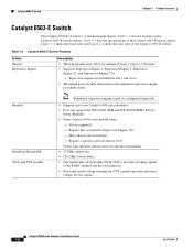
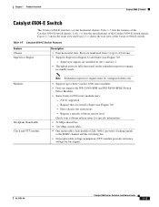
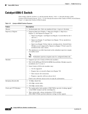
... Overview Catalyst 6506-E Switch The Catalyst 6506-E switch is a 6-slot horizontal chassis. Table 1-9 Catalyst 6506-E Switch Features Feature Chassis Supervisor Engines Descriptions • Six horizontal slots. Modules Backplane Bandwidth Clock and VTT Modules Note Redundant supervisor engines must be supported - Supervisor Engine 32 and Supervisor Engine 720 are installed in the same chassis. • The uplink ports are numbered from 1 (top) to 6 (bottom). • Supports Supervisor Engine 1, Supervisor Engine 2, Supervisor Engine 32, and Supervisor Engine...
... Overview Catalyst 6506-E Switch The Catalyst 6506-E switch is a 6-slot horizontal chassis. Table 1-9 Catalyst 6506-E Switch Features Feature Chassis Supervisor Engines Descriptions • Six horizontal slots. Modules Backplane Bandwidth Clock and VTT Modules Note Redundant supervisor engines must be supported - Supervisor Engine 32 and Supervisor Engine 720 are installed in the same chassis. • The uplink ports are numbered from 1 (top) to 6 (bottom). • Supports Supervisor Engine 1, Supervisor Engine 2, Supervisor Engine 32, and Supervisor Engine...
Installation Guide
Page 51
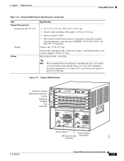
... vents and a minimum horizontal separation of 12 inches (30.5 cm) between two chassis to install in . (55.0 cm). • Chassis requires 12 RU. • The Catalyst 6506-E switch chassis is designed to prevent overheating. Figure 1-8 Catalyst 6506-E Switch Supervisor engine Redundant supervisor engine Switching modules Fan assembly 1 2 3 4 FAN STATUS 5 6 WS-X6K-SUP2-2GE STATUS SYSTEMCONSOLPEWR MGRMETSET SUPERVISOR2 CONSOLE WS-X6K-SUP2-2GE...
... vents and a minimum horizontal separation of 12 inches (30.5 cm) between two chassis to install in . (55.0 cm). • Chassis requires 12 RU. • The Catalyst 6506-E switch chassis is designed to prevent overheating. Figure 1-8 Catalyst 6506-E Switch Supervisor engine Redundant supervisor engine Switching modules Fan assembly 1 2 3 4 FAN STATUS 5 6 WS-X6K-SUP2-2GE STATUS SYSTEMCONSOLPEWR MGRMETSET SUPERVISOR2 CONSOLE WS-X6K-SUP2-2GE...
Installation Guide
Page 52
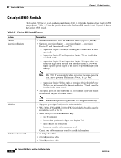
... chassis to 9 (bottom). • Supports Supervisor Engine 1, Supervisor Engine 2, Supervisor Engine 32, and Supervisor Engine 720. - Not be powered from 1 (top) to power the high-speed fan tray. Table 1-12 lists the specifications of the Catalyst 6509 switch chassis. Note The 2500 W power supply, when supporting the high-speed fan tray, can be supported - Catalyst 6509 Switch Chapter 1 Product Overview Catalyst 6509 Switch The Catalyst 6509 switch is a 9-slot horizontal chassis. Supervisor Engine 32 and Supervisor Engine...
... chassis to 9 (bottom). • Supports Supervisor Engine 1, Supervisor Engine 2, Supervisor Engine 32, and Supervisor Engine 720. - Not be powered from 1 (top) to power the high-speed fan tray. Table 1-12 lists the specifications of the Catalyst 6509 switch chassis. Note The 2500 W power supply, when supporting the high-speed fan tray, can be supported - Catalyst 6509 Switch Chapter 1 Product Overview Catalyst 6509 Switch The Catalyst 6509 switch is a 9-slot horizontal chassis. Supervisor Engine 32 and Supervisor Engine...

Installation Guide
Page 53
... (WS-C6K-VTT=) provide reference voltage for Supervisor Engine 32 and Supervisor Engine 720. Supports Supervisor Engine 1 and Supervisor Engine 2. These fan tray models are not field replaceable. WS-C6K-9SLOT-FAN2 (Optional high-speed fan tray-630 CFM). Red-One or more individual fans have failed. - Chapter 1 Product Overview Catalyst 6509 Switch Table 1-11 Catalyst 6509 Switch Features (continued) Feature Clock and VTT...
... (WS-C6K-VTT=) provide reference voltage for Supervisor Engine 32 and Supervisor Engine 720. Supports Supervisor Engine 1 and Supervisor Engine 2. These fan tray models are not field replaceable. WS-C6K-9SLOT-FAN2 (Optional high-speed fan tray-630 CFM). Red-One or more individual fans have failed. - Chapter 1 Product Overview Catalyst 6509 Switch Table 1-11 Catalyst 6509 Switch Features (continued) Feature Clock and VTT...
