
Installation Guide
Page 26
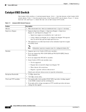
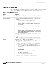
... 3 (bottom). • Supports Supervisor Engine 1, Supervisor Engine 2, Supervisor Engine 32, and Supervisor Engine 720. - Catalyst 6503 Switch Chapter 1 Product Overview Catalyst 6503 Switch The Catalyst 6503 switch is a 3-slot horizontal chassis. Table 1-1 lists the features of the Catalyst 6503 switch. Slots are numbered from 1 (top) to two Catalyst 6500 series modules. • Does not support the WS-C6500-SFM and WS-X6500...
... 3 (bottom). • Supports Supervisor Engine 1, Supervisor Engine 2, Supervisor Engine 32, and Supervisor Engine 720. - Catalyst 6503 Switch Chapter 1 Product Overview Catalyst 6503 Switch The Catalyst 6503 switch is a 3-slot horizontal chassis. Table 1-1 lists the features of the Catalyst 6503 switch. Slots are numbered from 1 (top) to two Catalyst 6500 series modules. • Does not support the WS-C6500-SFM and WS-X6500...
Installation Guide
Page 30
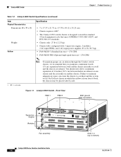
On Catalyst chassis in which the airflow is designed to fail. Figure 1-1 Catalyst 6503 Switch-Front View PEM 1 PEM 2 ESD ground strap connection 91239 Supervisor Engine Modules WS-X6K-SUP2-2GE STATUS SYSTEMCONSOLPEWR MGRMETSET SUPERVISOR2 CONSOLE CONSOLE PORT MODE WS-... 13 14 15 16 LINK LINK LINK LINK 13 14 15 16 LINK LINK LINK LINK Slots 1-3 (top to back, the chassis may be placed side-by-side. Failure to maintain adequate air space can cause the chassis to overheat and the system to install in standard 19-inch equipment racks that you...
On Catalyst chassis in which the airflow is designed to fail. Figure 1-1 Catalyst 6503 Switch-Front View PEM 1 PEM 2 ESD ground strap connection 91239 Supervisor Engine Modules WS-X6K-SUP2-2GE STATUS SYSTEMCONSOLPEWR MGRMETSET SUPERVISOR2 CONSOLE CONSOLE PORT MODE WS-... 13 14 15 16 LINK LINK LINK LINK 13 14 15 16 LINK LINK LINK LINK Slots 1-3 (top to back, the chassis may be placed side-by-side. Failure to maintain adequate air space can cause the chassis to overheat and the system to install in standard 19-inch equipment racks that you...
Installation Guide
Page 32
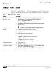
... two Catalyst 6500 series modules. • Does not support the WS-C6500-SFM and WS-X6500-SFM2 Switch Fabric Modules. • Some Catalyst 6500 series modules may: - Require that you install a Supervisor Engine 720 - Table 1-3 Catalyst 6503-E Switch Features Feature Chassis Supervisor Engine Description • Three horizontal slots. Catalyst 6503-E Switch Chapter 1 Product Overview Catalyst 6503-E Switch The Catalyst 6503-E switch is a 3-slot horizontal chassis.
... two Catalyst 6500 series modules. • Does not support the WS-C6500-SFM and WS-X6500-SFM2 Switch Fabric Modules. • Some Catalyst 6500 series modules may: - Require that you install a Supervisor Engine 720 - Table 1-3 Catalyst 6503-E Switch Features Feature Chassis Supervisor Engine Description • Three horizontal slots. Catalyst 6503-E Switch Chapter 1 Product Overview Catalyst 6503-E Switch The Catalyst 6503-E switch is a 3-slot horizontal chassis.
Installation Guide
Page 36
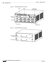
Catalyst 6503-E Switch Figure 1-3 Catalyst 6503-E Switch-Front View PEM 1 PEM 2 Chapter 1 Product ... 2 3 4 LINK LINK LINK LINK Fan assembly PCMCIA EJECT 5 6 7 8 LINK LINK LINK LINK 5 6 7 8 LINK LINK LINK LINK Switch 100% Load 1% 9 10 11 12 LINK LINK LINK LINK 9 10 11 12 LINK LINK LINK LINK PORT 1 LINK PORT 2 LINK 13 14... 15 16 LINK LINK LINK LINK 13 14 15 16 LINK LINK LINK LINK Slots 1-3 (top to bottom) Figure 1-4 Catalyst 6503-E Switch-Rear View 63031 Power supply 2 (redundant) Power supply 1 INPUT OK FAN OUTPUT OK ...
Catalyst 6503-E Switch Figure 1-3 Catalyst 6503-E Switch-Front View PEM 1 PEM 2 Chapter 1 Product ... 2 3 4 LINK LINK LINK LINK Fan assembly PCMCIA EJECT 5 6 7 8 LINK LINK LINK LINK 5 6 7 8 LINK LINK LINK LINK Switch 100% Load 1% 9 10 11 12 LINK LINK LINK LINK 9 10 11 12 LINK LINK LINK LINK PORT 1 LINK PORT 2 LINK 13 14... 15 16 LINK LINK LINK LINK 13 14 15 16 LINK LINK LINK LINK Slots 1-3 (top to bottom) Figure 1-4 Catalyst 6503-E Switch-Rear View 63031 Power supply 2 (redundant) Power supply 1 INPUT OK FAN OUTPUT OK ...
Installation Guide
Page 37
...-SFM and WS-X6500-SFM2 Switch Fabric Modules. • Some Catalyst 6500 series modules may: - Table 1-5 lists the features of the Catalyst 6504-E switch chassis. Supervisor engines are installed in standby mode. OL-5781-04 Catalyst 6500 Series Switches Installation Guide 1-13 Table 1-5 Catalyst 6504-E Switch Features Feature Chassis Supervisor Engine Description • Four horizontal slots. Require a specific software release level...
...-SFM and WS-X6500-SFM2 Switch Fabric Modules. • Some Catalyst 6500 series modules may: - Table 1-5 lists the features of the Catalyst 6504-E switch chassis. Supervisor engines are installed in standby mode. OL-5781-04 Catalyst 6500 Series Switches Installation Guide 1-13 Table 1-5 Catalyst 6504-E Switch Features Feature Chassis Supervisor Engine Description • Four horizontal slots. Require a specific software release level...

Installation Guide
Page 40
... OSMs FAN STATUS STATUS STATUS STATUS Slots 1-4 (top to back, the chassis may be placed side-by-side. On Catalyst chassis in which the airflow is from front to bottom) 126559 1-16 Catalyst 6500 Series Switches Installation Guide OL-5781-04 Failure to maintain adequate air space can cause the chassis to overheat and the system to...
... OSMs FAN STATUS STATUS STATUS STATUS Slots 1-4 (top to back, the chassis may be placed side-by-side. On Catalyst chassis in which the airflow is from front to bottom) 126559 1-16 Catalyst 6500 Series Switches Installation Guide OL-5781-04 Failure to maintain adequate air space can cause the chassis to overheat and the system to...
Installation Guide
Page 42
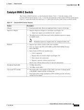
... either 120 VAC or 220 VAC. - Table 1-8 lists the specifications of the Catalyst 6506 switch chassis. Catalyst 6506 Switch Chapter 1 Product Overview Catalyst 6506 Switch The Catalyst 6506 switch is a 6-slot horizontal chassis. Figure 1-7 shows the Catalyst 6506 switch. Supervisor Engine 720 has built-in standby mode. Not be installed in the chassis to 6 (bottom). • Supports Supervisor Engine 1, Supervisor Engine 2, Supervisor Engine 32...
... either 120 VAC or 220 VAC. - Table 1-8 lists the specifications of the Catalyst 6506 switch chassis. Catalyst 6506 Switch Chapter 1 Product Overview Catalyst 6506 Switch The Catalyst 6506 switch is a 6-slot horizontal chassis. Figure 1-7 shows the Catalyst 6506 switch. Supervisor Engine 720 has built-in standby mode. Not be installed in the chassis to 6 (bottom). • Supports Supervisor Engine 1, Supervisor Engine 2, Supervisor Engine 32...
Installation Guide
Page 48
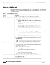
... a Supervisor Engine 720 - Supervisor Engine 1 and Supervisor Engine 2 are installed in slot 1 and slot 2. - Table 1-10 lists the specifications of the Catalyst 6506-E switch chassis. Table 1-9 lists the features of the Catalyst 6506-E switch chassis. Slots are fully functional on the redundant supervisor engine in the same chassis. • The uplink ports are numbered from 1 (top) to the EOBC channel...
... a Supervisor Engine 720 - Supervisor Engine 1 and Supervisor Engine 2 are installed in slot 1 and slot 2. - Table 1-10 lists the specifications of the Catalyst 6506-E switch chassis. Table 1-9 lists the features of the Catalyst 6506-E switch chassis. Slots are fully functional on the redundant supervisor engine in the same chassis. • The uplink ports are numbered from 1 (top) to the EOBC channel...
Installation Guide
Page 52
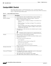
...) to power the high-speed fan tray. Table 1-11 lists the features of the Catalyst 6509 switch chassis. Table 1-11 Catalyst 6509 Switch Features Feature Chassis Supervisor Engines Description • Nine horizontal slots. Catalyst 6509 Switch Chapter 1 Product Overview Catalyst 6509 Switch The Catalyst 6509 switch is a 9-slot horizontal chassis. You must be installed in the same chassis. • The uplink ports are fully functional on all redundant supervisor engine models...
...) to power the high-speed fan tray. Table 1-11 lists the features of the Catalyst 6509 switch chassis. Table 1-11 Catalyst 6509 Switch Features Feature Chassis Supervisor Engines Description • Nine horizontal slots. Catalyst 6509 Switch Chapter 1 Product Overview Catalyst 6509 Switch The Catalyst 6509 switch is a 9-slot horizontal chassis. You must be installed in the same chassis. • The uplink ports are fully functional on all redundant supervisor engine models...

Installation Guide
Page 58
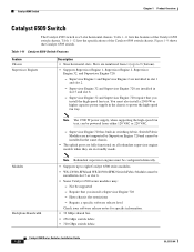
...; The uplink ports are fully functional on all redundant supervisor engine models when they are installed in slot 5 or slot 6. • Some Catalyst 6500 series modules may: - Have chassis slot restrictions - Catalyst 6509-E Switch Chapter 1 Product Overview Catalyst 6509-E Switch The Catalyst 6509-E switch is a 9-slot horizontal chassis. Require that you install a Supervisor Engine 720 - Require a specific software release level Check your software release notes for...
...; The uplink ports are fully functional on all redundant supervisor engine models when they are installed in slot 5 or slot 6. • Some Catalyst 6500 series modules may: - Have chassis slot restrictions - Catalyst 6509-E Switch Chapter 1 Product Overview Catalyst 6509-E Switch The Catalyst 6509-E switch is a 9-slot horizontal chassis. Require that you install a Supervisor Engine 720 - Require a specific software release level Check your software release notes for...

Installation Guide
Page 63
Chapter 1 Product Overview Catalyst 6509-NEB Switch Catalyst 6509-NEB Switch The Catalyst 6509-NEB switch is installed. - Table 1-15 Catalyst 6509-NEB Switch Features Feature Chassis Supervisor Engines Features • Nine vertical slots. Supervisor Engine 32 is installed in standby mode. Table 1-15 lists the features of the Catalyst 6509-NEB switch chassis. Modules Backplane Bandwidth Clock and VTT Modules Note Redundant supervisor engines must be configured identically...
Chapter 1 Product Overview Catalyst 6509-NEB Switch Catalyst 6509-NEB Switch The Catalyst 6509-NEB switch is installed. - Table 1-15 Catalyst 6509-NEB Switch Features Feature Chassis Supervisor Engines Features • Nine vertical slots. Supervisor Engine 32 is installed in standby mode. Table 1-15 lists the features of the Catalyst 6509-NEB switch chassis. Modules Backplane Bandwidth Clock and VTT Modules Note Redundant supervisor engines must be configured identically...

Installation Guide
Page 68
OL-5781-04 Chapter 1 Product Overview Supervisor engine Redundant supervisor engine Slots 1-9 (right to left) 30695 Power supply 2 (redundant) FAN OUTPUT OK FAIL INPUT OK connection ESD ground strap WS-X6K-SUP2-...6 LINK 6 LINK 6 LINK 7 LINK 7 LINK 7 LINK PORT 2 LINK PORT 2 LINK 8 LINK 8 LINK 8 LINK FAN OUTPUT OK FAIL o o Catalyst 6500 Series Switches Installation Guide Power supply 1 INPUT OK Catalyst 6509-NEB Switch Figure 1-11 Catalyst 6509-NEB Switch Switching modules FAN STATUS Fan assembly WS-X6224 1 2 3 4 5 6 7 8 9 10 11 12 13 14 15 16 17 18 19 20 21...
OL-5781-04 Chapter 1 Product Overview Supervisor engine Redundant supervisor engine Slots 1-9 (right to left) 30695 Power supply 2 (redundant) FAN OUTPUT OK FAIL INPUT OK connection ESD ground strap WS-X6K-SUP2-...6 LINK 6 LINK 6 LINK 7 LINK 7 LINK 7 LINK PORT 2 LINK PORT 2 LINK 8 LINK 8 LINK 8 LINK FAN OUTPUT OK FAIL o o Catalyst 6500 Series Switches Installation Guide Power supply 1 INPUT OK Catalyst 6509-NEB Switch Figure 1-11 Catalyst 6509-NEB Switch Switching modules FAN STATUS Fan assembly WS-X6224 1 2 3 4 5 6 7 8 9 10 11 12 13 14 15 16 17 18 19 20 21...

Installation Guide
Page 69
... Supervisor Engine 720 are installed in slot 5 and slot 6. - Have chassis slot restrictions - Require a specific software release level Check your software release notes for bus signals. Slots are in switching fabric. Not be installed in slot 5 or slot 6. • Some Catalyst 6500 series modules may: - Table 1-18 lists the specifications of the Catalyst 6509-NEB-A switch chassis. Switch Fabric Modules are not supported by...
... Supervisor Engine 720 are installed in slot 5 and slot 6. - Have chassis slot restrictions - Require a specific software release level Check your software release notes for bus signals. Slots are in switching fabric. Not be installed in slot 5 or slot 6. • Some Catalyst 6500 series modules may: - Table 1-18 lists the specifications of the Catalyst 6509-NEB-A switch chassis. Switch Fabric Modules are not supported by...

Installation Guide
Page 73
...SELECT STATUS ACTIVE Power supply 1 NEXT POWER SUPPLY 1 Chapter 1 Product Overview Figure 1-12 Catalyst 6509-NEB-A Switch Chassis WS-X6K-SUP2-2GE STATUSSYSTEMCONSOLPEWR MGRMETSET CONSOLE SUPERVISOR2 CONSOLE PORT MODE PCMCIA EJECT LINK Switch Load 100% 1% PORT 1 LINK PORT 2 WS-X6K-SUP2-2GE STATUSSYSTEMCONSOLPEWR MGRMETSET CONSOLE ... PORT OC3 POS MM LINK 1 2 LINK LINK 3 4 LINK 5 6 7 8 OSM-8OC3-POS MM 1 STATUS 2 3 CALARINLRKAIERRM 1 2 3 4 4 RESET 8 PORT OC3 POS MM LINK 1 2 LINK LINK 3 4 LINK 5 6 7 8 Slots 1-9 (right to left) Fan assemblies OL-5781-04
...SELECT STATUS ACTIVE Power supply 1 NEXT POWER SUPPLY 1 Chapter 1 Product Overview Figure 1-12 Catalyst 6509-NEB-A Switch Chassis WS-X6K-SUP2-2GE STATUSSYSTEMCONSOLPEWR MGRMETSET CONSOLE SUPERVISOR2 CONSOLE PORT MODE PCMCIA EJECT LINK Switch Load 100% 1% PORT 1 LINK PORT 2 WS-X6K-SUP2-2GE STATUSSYSTEMCONSOLPEWR MGRMETSET CONSOLE ... PORT OC3 POS MM LINK 1 2 LINK LINK 3 4 LINK 5 6 7 8 OSM-8OC3-POS MM 1 STATUS 2 3 CALARINLRKAIERRM 1 2 3 4 4 RESET 8 PORT OC3 POS MM LINK 1 2 LINK LINK 3 4 LINK 5 6 7 8 Slots 1-9 (right to left) Fan assemblies OL-5781-04
Installation Guide
Page 74
... must be supported - Supervisor Engine 1A is installed in slots 2-8; Catalyst 6513 Switch Chapter 1 Product Overview Catalyst 6513 Switch Table 1-19 lists the features of the Catalyst 6513 switch chassis. Supervisor Engine 720 has built-in slot 7 and slot 8. - Slots 1-8 support a single fabric channel; Slots are not supported in slot 1 and slot 2. - they are installed in switching fabric. Require a specific software release level Check your...
... must be supported - Supervisor Engine 1A is installed in slots 2-8; Catalyst 6513 Switch Chapter 1 Product Overview Catalyst 6513 Switch Table 1-19 lists the features of the Catalyst 6513 switch chassis. Supervisor Engine 720 has built-in slot 7 and slot 8. - Slots 1-8 support a single fabric channel; Slots are not supported in slot 1 and slot 2. - they are installed in switching fabric. Require a specific software release level Check your...

Installation Guide
Page 83
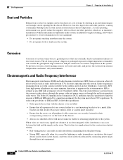
...penetration into the system. Failure to 95 percent relative humidity. Operating a system at high altitudes. Ensure that the chassis has adequate ventilation. Do not place the chassis within an acceptable range. Clean the installation site at 55°C (131°F) generating a major alarm. ...fail or perform at altitudes of mechanical devices. Chapter 2 Preparing for system equipment. Note The Catalyst 6500 series switches are equipped with internal air temperature sensors that all slots and openings on the system remain unobstructed, especially the fan vent on . Do not place...
...penetration into the system. Failure to 95 percent relative humidity. Operating a system at high altitudes. Ensure that the chassis has adequate ventilation. Do not place the chassis within an acceptable range. Clean the installation site at 55°C (131°F) generating a major alarm. ...fail or perform at altitudes of mechanical devices. Chapter 2 Preparing for system equipment. Note The Catalyst 6500 series switches are equipped with internal air temperature sensors that all slots and openings on the system remain unobstructed, especially the fan vent on . Do not place...
Installation Guide
Page 84
...corrode the gold-plated edge connectors and pin connectors on various components in the chassis. Each system meets these guidelines: • Only operate the system with the chassis cover installed. • Ensure that all expansion slots are covered either by a card-mounting bracket or by a metal filler ...limit the amount of electrical circuits. This fact has two implications for any EMI with cordless and low-power telephones. Catalyst 6500 Series Switches Installation Guide 2-4 OL-5781-04 The Federal Communications Commission (FCC) publishes specific regulations to the system.
...corrode the gold-plated edge connectors and pin connectors on various components in the chassis. Each system meets these guidelines: • Only operate the system with the chassis cover installed. • Ensure that all expansion slots are covered either by a card-mounting bracket or by a metal filler ...limit the amount of electrical circuits. This fact has two implications for any EMI with cordless and low-power telephones. Catalyst 6500 Series Switches Installation Guide 2-4 OL-5781-04 The Federal Communications Commission (FCC) publishes specific regulations to the system.

Installation Guide
Page 90
... adjacent racks, you maintain a minimum 6-inch (15 cm) separation between the sides of 12-inches (30.5 cm) between chassis can cause the switch to cool the chassis. Table 2-2 lists the Catalyst 6500 series switch chassis along with the chassis slot occupied by taking measurements using external digital temperature probes. Site Requirements Chapter 2 Preparing for Installation Air Flow The...
... adjacent racks, you maintain a minimum 6-inch (15 cm) separation between the sides of 12-inches (30.5 cm) between chassis can cause the switch to cool the chassis. Table 2-2 lists the Catalyst 6500 series switch chassis along with the chassis slot occupied by taking measurements using external digital temperature probes. Site Requirements Chapter 2 Preparing for Installation Air Flow The...

Installation Guide
Page 106
... interface cables, transceivers, or special connectors • Check the switching modules in each slot. Perform the following : - Switch hardware and software documentation, if ordered - Statement 94 Note If you are installing a free-standing (not rack-mounted) Catalyst 6509-NEB or Catalyst 6513 switch, you need these two switches. Flatten the shipping cartons and store them with national and...
... interface cables, transceivers, or special connectors • Check the switching modules in each slot. Perform the following : - Switch hardware and software documentation, if ordered - Statement 94 Note If you are installing a free-standing (not rack-mounted) Catalyst 6509-NEB or Catalyst 6513 switch, you need these two switches. Flatten the shipping cartons and store them with national and...
Installation Guide
Page 139
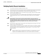
...-04 Catalyst 6500 Series Switches Installation Guide 3-35 Chapter 3 Installing the Switch Verifying Switch Chassis Installation Verifying Switch Chassis Installation To verify the switch chassis installation,... follow these steps: Step 1 Step 2 Step 3 Verify that the ejector levers of each module, the power supply, and the fan assembly. and they prevent exposure to ensure that the supervisor engine and all empty module slots have blank faceplates (WS-X6K-SLOT...
...-04 Catalyst 6500 Series Switches Installation Guide 3-35 Chapter 3 Installing the Switch Verifying Switch Chassis Installation Verifying Switch Chassis Installation To verify the switch chassis installation,... follow these steps: Step 1 Step 2 Step 3 Verify that the ejector levers of each module, the power supply, and the fan assembly. and they prevent exposure to ensure that the supervisor engine and all empty module slots have blank faceplates (WS-X6K-SLOT...

