
Installation Guide
Page 149
... 3000 W, 4000 W, and 6000 W AC-input power supplies in the Catalyst 6500 series switches that the power supply LEDs are removed and installed using the same procedures. Verify power supply operation by checking that support them. In case of the power cord to ensure protective grounding continuity. Chapter...LED is green • OUTPUT FAIL LED is operating. Step 8 Step 9 Turn the switch on the power supply. OL-5781-04 Catalyst 6500 Series Switches Installation Guide 4-9 Step 7 Connect the other end of a power source failure, the second source will most likely still be tight to ...
... 3000 W, 4000 W, and 6000 W AC-input power supplies in the Catalyst 6500 series switches that the power supply LEDs are removed and installed using the same procedures. Verify power supply operation by checking that support them. In case of the power cord to ensure protective grounding continuity. Chapter...LED is green • OUTPUT FAIL LED is operating. Step 8 Step 9 Turn the switch on the power supply. OL-5781-04 Catalyst 6500 Series Switches Installation Guide 4-9 Step 7 Connect the other end of a power source failure, the second source will most likely still be tight to ...
Installation Guide
Page 152
...power problem, see the "Identifying Startup Problems" section on page E-3 for a list of supported AC power cords. Step 8 Step 9 Turn the power switch to Appendix A for troubleshooting information. 4-12 Catalyst 6500 Series Switches Installation Guide OL-5781-04 Slide the power supply into the power supply, and tighten the... 6 Grasp the power supply handle with dual power supplies, connect each power supply to the power supply. Place your other end of a power source failure, the second source should still be available. Switching the power switch to an AC-input power source.
...power problem, see the "Identifying Startup Problems" section on page E-3 for a list of supported AC power cords. Step 8 Step 9 Turn the power switch to Appendix A for troubleshooting information. 4-12 Catalyst 6500 Series Switches Installation Guide OL-5781-04 Slide the power supply into the power supply, and tighten the... 6 Grasp the power supply handle with dual power supplies, connect each power supply to the power supply. Place your other end of a power source failure, the second source should still be available. Switching the power switch to an AC-input power source.

Installation Guide
Page 194
...PEM Warning Before performing any of the chassis so that you have access to an AC-input power source. Negative (-) Note It is off to the DC circuit for a list of supported AC power cords.) Step 6 Connect the other end of the power cord to the PEM... terminal block screws. (See Figure 4-45.) Disconnect the DC-input wires from the DC circuit. In case of adhesive tape over the circuit breaker handle to a separate input source. Positive (+) 2. Step 7 Turn the power switch to disconnect the system ground connection. 4-54 Catalyst 6500 Series Switches...
...PEM Warning Before performing any of the chassis so that you have access to an AC-input power source. Negative (-) Note It is off to the DC circuit for a list of supported AC power cords.) Step 6 Connect the other end of the power cord to the PEM... terminal block screws. (See Figure 4-45.) Disconnect the DC-input wires from the DC circuit. In case of adhesive tape over the circuit breaker handle to a separate input source. Positive (+) 2. Step 7 Turn the power switch to disconnect the system ground connection. 4-54 Catalyst 6500 Series Switches...

Installation Guide
Page 279
OL-5781-04 Catalyst 6500 Series Switches Installation Guide B-7 The only restrictions are that each SFP port must not exceed the stipulated cable length for reliable communications. Appendix B Transceivers, Module Connectors, and Cable Specifications Figure B-4 1000BASE-T SFP Transceiver Module (GLC-T) Transceivers 87922 Figure B-5 1000BASE-X SFP Transceiver Modules (GLC-SX-MM, GLC-LH-SM, and GLC-ZX-SM) 114944 Note You can use any combination of SFP modules that the cable must match the wavelength specifications on the other end of the cable and that your Cisco device supports.
OL-5781-04 Catalyst 6500 Series Switches Installation Guide B-7 The only restrictions are that each SFP port must not exceed the stipulated cable length for reliable communications. Appendix B Transceivers, Module Connectors, and Cable Specifications Figure B-4 1000BASE-T SFP Transceiver Module (GLC-T) Transceivers 87922 Figure B-5 1000BASE-X SFP Transceiver Modules (GLC-SX-MM, GLC-LH-SM, and GLC-ZX-SM) 114944 Note You can use any combination of SFP modules that the cable must match the wavelength specifications on the other end of the cable and that your Cisco device supports.
Installation Guide
Page 302
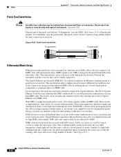
... can limit the reach of modes. (See Figure B-21.) B-30 Catalyst 6500 Series Switches Installation Guide OL-5781-04 These paths might become two independent pulses. Statement 1051 Plug the end of its very high baud rate and its long MMF cable lengths. ...case transceivers. Cables Appendix B Transceivers, Module Connectors, and Cable Specifications Patch Cord Installation Warning Invisible laser radiation may be reliably supported. The results create an additional element of jitter that occurs with optical instruments. The Gigabit Ethernet specification (IEEE 802.3z) ...
... can limit the reach of modes. (See Figure B-21.) B-30 Catalyst 6500 Series Switches Installation Guide OL-5781-04 These paths might become two independent pulses. Statement 1051 Plug the end of its very high baud rate and its long MMF cable lengths. ...case transceivers. Cables Appendix B Transceivers, Module Connectors, and Cable Specifications Patch Cord Installation Warning Invisible laser radiation may be reliably supported. The results create an additional element of jitter that occurs with optical instruments. The Gigabit Ethernet specification (IEEE 802.3z) ...


