
Installation Guide
Page 30
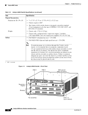
On Catalyst chassis in which the airflow is designed to install in . (17.78 x 44.12 x 55.25 cm). • Chassis requires 4 RU1. • The Catalyst 6503 switch chassis is from front to back, the chassis may be placed side-by-side. Figure 1-1 Catalyst 6503 Switch-Front View PEM 1 PEM 2 ESD ground strap connection 91239 Supervisor Engine Modules WS-X6K-SUP2...
On Catalyst chassis in which the airflow is designed to install in . (17.78 x 44.12 x 55.25 cm). • Chassis requires 4 RU1. • The Catalyst 6503 switch chassis is from front to back, the chassis may be placed side-by-side. Figure 1-1 Catalyst 6503 Switch-Front View PEM 1 PEM 2 ESD ground strap connection 91239 Supervisor Engine Modules WS-X6K-SUP2...
Installation Guide
Page 35
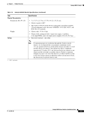
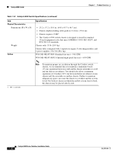
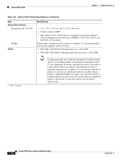
Chapter 1 Product Overview Catalyst 6503-E Switch Table 1-4 Catalyst 6503-E Switch Specifications (continued) Item Physical Characteristics Dimensions (H x W x D) Weight Airflow Specification • 7 x 17.37 x 21.75 in. (17.78 x 44.12 x 55.25 cm). • Chassis requires 4 RU1. • The Catalyst 6503-E switch chassis is from front to back, the chassis may be placed side-by-side. You should also allow a minimum separation...
Chapter 1 Product Overview Catalyst 6503-E Switch Table 1-4 Catalyst 6503-E Switch Specifications (continued) Item Physical Characteristics Dimensions (H x W x D) Weight Airflow Specification • 7 x 17.37 x 21.75 in. (17.78 x 44.12 x 55.25 cm). • Chassis requires 4 RU1. • The Catalyst 6503-E switch chassis is from front to back, the chassis may be placed side-by-side. You should also allow a minimum separation...

Installation Guide
Page 40
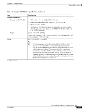
... separation of 12 inches (30.5 cm) between a wall and the chassis air intake or a wall and the chassis air exhaust. On Catalyst chassis in which the airflow is from front to back, the chassis may be placed side-by-side. Catalyst 6504-E Switch Chapter 1 Product Overview Table 1-6 Catalyst 6504-E Switch Specifications (continued) Item Airflow Specification • FAN-MOD-4HS-300 CFM 1.
... separation of 12 inches (30.5 cm) between a wall and the chassis air intake or a wall and the chassis air exhaust. On Catalyst chassis in which the airflow is from front to back, the chassis may be placed side-by-side. Catalyst 6504-E Switch Chapter 1 Product Overview Table 1-6 Catalyst 6504-E Switch Specifications (continued) Item Airflow Specification • FAN-MOD-4HS-300 CFM 1.
Installation Guide
Page 46
On Catalyst chassis in which the airflow is designed to install in . (55.0 cm). • Chassis requires 12 RU. • The Catalyst 6506 switch chassis is from front to back, the chassis may be placed side-by-side. 1-22 Catalyst 6500 Series Switches Installation Guide OL-5781-04 Failure to maintain adequate air space can cause the chassis to overheat and the...
On Catalyst chassis in which the airflow is designed to install in . (55.0 cm). • Chassis requires 12 RU. • The Catalyst 6506 switch chassis is from front to back, the chassis may be placed side-by-side. 1-22 Catalyst 6500 Series Switches Installation Guide OL-5781-04 Failure to maintain adequate air space can cause the chassis to overheat and the...
Installation Guide
Page 51
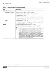
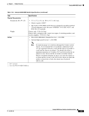
... Overview Catalyst 6506-E Switch Table 1-10 Catalyst 6506-E Switch Specifications (continued) Item Physical Characteristics Dimensions (H x W x D) Weight Airflow Specification • 19.2 x 17.5 x 18.2 in. (48.8 x 44.5 x 46.0 cm). • Chassis depth including cable guide is designed to prevent overheating. Note We recommend that you maintain a minimum air space of 6 inches (16 cm) between walls and the chassis air...
... Overview Catalyst 6506-E Switch Table 1-10 Catalyst 6506-E Switch Specifications (continued) Item Physical Characteristics Dimensions (H x W x D) Weight Airflow Specification • 19.2 x 17.5 x 18.2 in. (48.8 x 44.5 x 46.0 cm). • Chassis depth including cable guide is designed to prevent overheating. Note We recommend that you maintain a minimum air space of 6 inches (16 cm) between walls and the chassis air...
Installation Guide
Page 56
... cable guide is 21.64 in. (55.0 cm). • Chassis requires 15 RU1. • The Catalyst 6509 switch chassis is designed to install in which the airflow is from front to fail. Chassis fully configured with 1 supervisor engine, 8 switching modules, and 2 power supplies: 194.5 lb (88.2 kg). On Catalyst chassis in standard 19-inch equipment racks that you maintain a minimum...
... cable guide is 21.64 in. (55.0 cm). • Chassis requires 15 RU1. • The Catalyst 6509 switch chassis is designed to install in which the airflow is from front to fail. Chassis fully configured with 1 supervisor engine, 8 switching modules, and 2 power supplies: 194.5 lb (88.2 kg). On Catalyst chassis in standard 19-inch equipment racks that you maintain a minimum...
Installation Guide
Page 61
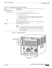
... placed side-by-side. Chapter 1 Product Overview Catalyst 6509-E Switch Table 1-14 Catalyst 6509-E Switch Specifications (continued) Item Physical Characteristics Dimensions (H x W x D) Weight Airflow Specification • 24.5 x 17.5 x 18.2 in. (62.2 x 44.5 x 46.0 cm). • Chassis depth including cable guide is 21.64 in. (55.0 cm). • Chassis requires 15 RU1. • The Catalyst 6509-E switch chassis is designed to install in which the...
... placed side-by-side. Chapter 1 Product Overview Catalyst 6509-E Switch Table 1-14 Catalyst 6509-E Switch Specifications (continued) Item Physical Characteristics Dimensions (H x W x D) Weight Airflow Specification • 24.5 x 17.5 x 18.2 in. (62.2 x 44.5 x 46.0 cm). • Chassis depth including cable guide is 21.64 in. (55.0 cm). • Chassis requires 15 RU1. • The Catalyst 6509-E switch chassis is designed to install in which the...
Installation Guide
Page 67
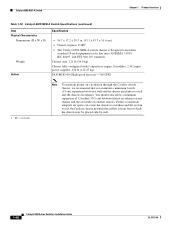
..., and ETS 300-119 standards. On Catalyst chassis in which the airflow is designed to install in . (84.6 x 43.7 x 46.0 cm). • Chassis requires 20 RU1. • The Catalyst 6509-NEB switch chassis is from front to fail. Chapter 1 Product Overview Catalyst 6509-NEB Switch Table 1-16 Catalyst 6509-NEB Switch Specifications (continued) Item Physical Characteristics Dimensions (H x W x D) Weight Airflow Specification • 33.3 x 17.2 x 18.1 in...
..., and ETS 300-119 standards. On Catalyst chassis in which the airflow is designed to install in . (84.6 x 43.7 x 46.0 cm). • Chassis requires 20 RU1. • The Catalyst 6509-NEB switch chassis is from front to fail. Chapter 1 Product Overview Catalyst 6509-NEB Switch Table 1-16 Catalyst 6509-NEB Switch Specifications (continued) Item Physical Characteristics Dimensions (H x W x D) Weight Airflow Specification • 33.3 x 17.2 x 18.1 in...
Installation Guide
Page 72
... fan tray)-760 CFM 1. On Catalyst chassis in standard 19-inch equipment racks that you maintain a minimum 6-inch (15 cm) separation between the hot air exhaust on one chassis and the air intake on another chassis. Catalyst 6509-NEB-A Switch Chapter 1 Product Overview Table 1-18 Catalyst 6509-NEB-A Switch Specifications (continued) Item Physical Characteristics Dimensions (H x W x D) Weight Airflow Specification • 36.7 x 17...
... fan tray)-760 CFM 1. On Catalyst chassis in standard 19-inch equipment racks that you maintain a minimum 6-inch (15 cm) separation between the hot air exhaust on one chassis and the air intake on another chassis. Catalyst 6509-NEB-A Switch Chapter 1 Product Overview Table 1-18 Catalyst 6509-NEB-A Switch Specifications (continued) Item Physical Characteristics Dimensions (H x W x D) Weight Airflow Specification • 36.7 x 17...
Installation Guide
Page 78
... a wall and the chassis air intake or a wall and the chassis air exhaust. On Catalyst chassis in which the airflow is designed to install in . (84.6 x 43.7 x 46.0 cm). • Chassis requires 20 RU1. • The Catalyst 6513 switch chassis is from front to back, the chassis may be placed side-by-side. 1-54 Catalyst 6500 Series Switches Installation Guide OL-5781...
... a wall and the chassis air intake or a wall and the chassis air exhaust. On Catalyst chassis in which the airflow is designed to install in . (84.6 x 43.7 x 46.0 cm). • Chassis requires 20 RU1. • The Catalyst 6513 switch chassis is from front to back, the chassis may be placed side-by-side. 1-54 Catalyst 6500 Series Switches Installation Guide OL-5781...
Installation Guide
Page 82
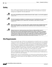
.... Statement 1017 Warning Before you prepare to install your Catalyst 6500 series switch. If the airflow is blocked or restricted, or if the intake air is too warm, an overtemperature condition can make chassis panels inaccessable and difficult to install, replace, or service... personnel should be allowed to maintain. Statement 1030 Warning This unit is inadequately ventilated can be aware of the switch chassis. 6-1 Catalyst 6500 Series Switches Installation Guide 2-2 OL-5781-04 Avoid using uninsulated exposed metal contacts, conductors, or terminals. A restricted access ...
.... Statement 1017 Warning Before you prepare to install your Catalyst 6500 series switch. If the airflow is blocked or restricted, or if the intake air is too warm, an overtemperature condition can make chassis panels inaccessable and difficult to install, replace, or service... personnel should be allowed to maintain. Statement 1030 Warning This unit is inadequately ventilated can be aware of the switch chassis. 6-1 Catalyst 6500 Series Switches Installation Guide 2-2 OL-5781-04 Avoid using uninsulated exposed metal contacts, conductors, or terminals. A restricted access ...

Installation Guide
Page 90
... engine monitor the internal air temperatures. To maintain proper air circulation through the Catalyst 6500 switch chassis, we strongly recommend that you should allow the chassis temperature to cool the supervisor engines, modules, and power supplies. After installing the chassis in which the airflow is insufficient airflow to be installed in adjacent racks, you verify that your...
... engine monitor the internal air temperatures. To maintain proper air circulation through the Catalyst 6500 switch chassis, we strongly recommend that you should allow the chassis temperature to cool the supervisor engines, modules, and power supplies. After installing the chassis in which the airflow is insufficient airflow to be installed in adjacent racks, you verify that your...
Installation Guide
Page 92
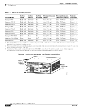
...-09= (air filter inserts). With Catalyst 6500 series chassis installed in a rack that is available for Installation Table 2-3 Chassis Air Flow Requirements Chassis Model Airflow Intake Airflow Exhaust Air Filter Minimum Clearance Minimum Clearance...Catalyst 6509-NEB Front Rear Catalyst 6509-NEB-A Front Rear No 6 in (15.2 cm) Yes3 6 in (15.2 cm) 12 in (30.5 cm) 12 in (30.5 cm) Figure 2-8 Figure 2-9 Catalyst 6513 Right side Left side No 6 in (15.2 cm) 12 in (30.5 cm) Figure 2-10 1. Site Requirements Chapter 2 Preparing for the Catalyst 6509-NEB-A switch chassis...
...-09= (air filter inserts). With Catalyst 6500 series chassis installed in a rack that is available for Installation Table 2-3 Chassis Air Flow Requirements Chassis Model Airflow Intake Airflow Exhaust Air Filter Minimum Clearance Minimum Clearance...Catalyst 6509-NEB Front Rear Catalyst 6509-NEB-A Front Rear No 6 in (15.2 cm) Yes3 6 in (15.2 cm) 12 in (30.5 cm) 12 in (30.5 cm) Figure 2-8 Figure 2-9 Catalyst 6513 Right side Left side No 6 in (15.2 cm) 12 in (30.5 cm) Figure 2-10 1. Site Requirements Chapter 2 Preparing for the Catalyst 6509-NEB-A switch chassis...

Installation Guide
Page 93
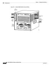
126561 Chapter 2 Preparing for Installation Figure 2-3 Catalyst 6504-E Switch Internal Airflow Module air exhaust Site Requirements FAN STATUS STATUS STATUS Figure 2-4 Catalyst 6506 Switch Internal Airflow Fan assembly Module air exhaust Fan status LED 1 2 3 4 FAN STATUS 5 6 WS-X6K-SUP2-2GE STATUS SYSTEMCONSOLPEWR MGRMETSET SUPERVISOR2 CONSOLE WS-X6K-SUP2-2GE STATUS SYSTEMCONSOLPEWR ... OK FAN OUTPUT OK FAIL INPUT OK FAN OUTPUT OK FAIL 18223 Module air inlet Module air inlet Power supply air exhaust OL-5781-04 Catalyst 6500 Series Switches Installation Guide 2-13
126561 Chapter 2 Preparing for Installation Figure 2-3 Catalyst 6504-E Switch Internal Airflow Module air exhaust Site Requirements FAN STATUS STATUS STATUS Figure 2-4 Catalyst 6506 Switch Internal Airflow Fan assembly Module air exhaust Fan status LED 1 2 3 4 FAN STATUS 5 6 WS-X6K-SUP2-2GE STATUS SYSTEMCONSOLPEWR MGRMETSET SUPERVISOR2 CONSOLE WS-X6K-SUP2-2GE STATUS SYSTEMCONSOLPEWR ... OK FAN OUTPUT OK FAIL INPUT OK FAN OUTPUT OK FAIL 18223 Module air inlet Module air inlet Power supply air exhaust OL-5781-04 Catalyst 6500 Series Switches Installation Guide 2-13
Installation Guide
Page 94
Site Requirements Figure 2-5 Catalyst 6506-E Switch Internal Airflow Fan assembly Module air exhaust Fan status LED 1 2 3 4 FAN STATUS 5 6 WS-X6K-SUP2-2GE STATUS SYSTEMCONSOLPEWR MGRMETSET SUPERVISOR2 CONSOLE WS-X6K-SUP2-2GE STATUS SYSTEMCONSOLPEWR ... o o INPUT OK FAN OUTPUT OK FAIL INPUT OK FAN OUTPUT OK FAIL Chapter 2 Preparing for Installation Module air inlet Power supply air exhaust 113675 2-14 Catalyst 6500 Series Switches Installation Guide OL-5781-04
Site Requirements Figure 2-5 Catalyst 6506-E Switch Internal Airflow Fan assembly Module air exhaust Fan status LED 1 2 3 4 FAN STATUS 5 6 WS-X6K-SUP2-2GE STATUS SYSTEMCONSOLPEWR MGRMETSET SUPERVISOR2 CONSOLE WS-X6K-SUP2-2GE STATUS SYSTEMCONSOLPEWR ... o o INPUT OK FAN OUTPUT OK FAIL INPUT OK FAN OUTPUT OK FAIL Chapter 2 Preparing for Installation Module air inlet Power supply air exhaust 113675 2-14 Catalyst 6500 Series Switches Installation Guide OL-5781-04
Installation Guide
Page 95
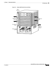
Chapter 2 Preparing for Installation Figure 2-6 Catalyst 6509 Switch Internal Airflow Fan assembly Module air exhaust Fan status LED 1 2 3 4 5 6 7 8 FAN ...STATUS LINK 8 PORT GIGABIT ETHERNET WS-X6408 1 2 STATUS LINK 8 PORT GIGABIT ETHERNET WS-X6408 1 2 8 PORT GIGABIT ETHERNET LINK LINK PCMCIA EJECT PCMCIA EJECT 3 4 Switch Load 100% 1% Switch Load 100% 1% PORT 1 LINK PORT 1 LINK 5 6 7 PORT 2 LINK PORT 2 LINK 8 LINK LINK LINK LINK LINK 3 4 5 6 7 8 LINK...Module air inlet Power supply air exhaust OL-5781-04 Catalyst 6500 Series Switches Installation Guide 2-15
Chapter 2 Preparing for Installation Figure 2-6 Catalyst 6509 Switch Internal Airflow Fan assembly Module air exhaust Fan status LED 1 2 3 4 5 6 7 8 FAN ...STATUS LINK 8 PORT GIGABIT ETHERNET WS-X6408 1 2 STATUS LINK 8 PORT GIGABIT ETHERNET WS-X6408 1 2 8 PORT GIGABIT ETHERNET LINK LINK PCMCIA EJECT PCMCIA EJECT 3 4 Switch Load 100% 1% Switch Load 100% 1% PORT 1 LINK PORT 1 LINK 5 6 7 PORT 2 LINK PORT 2 LINK 8 LINK LINK LINK LINK LINK 3 4 5 6 7 8 LINK...Module air inlet Power supply air exhaust OL-5781-04 Catalyst 6500 Series Switches Installation Guide 2-15
Installation Guide
Page 96
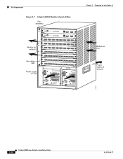
Site Requirements Figure 2-7 Catalyst 6509-E Switch Internal Airflow Fan assembly Module air exhaust Fan status LED 1 2 3 4 5 6 7 8 FAN... LINK 8 PORT GIGABIT ETHERNET WS-X6408 1 2 STATUS LINK 8 PORT GIGABIT ETHERNET WS-X6408 1 2 8 PORT GIGABIT ETHERNET LINK LINK PCMCIA EJECT PCMCIA EJECT 3 4 Switch Load 100% 1% Switch Load 100% 1% PORT 1 LINK PORT 1 LINK 5 6 7 PORT 2 LINK PORT 2 LINK 8 LINK LINK LINK LINK LINK 3 4 5 6 7 8 LINK... Installation Module air inlet Power supply air exhaust 113677 2-16 Catalyst 6500 Series Switches Installation Guide OL-5781-04
Site Requirements Figure 2-7 Catalyst 6509-E Switch Internal Airflow Fan assembly Module air exhaust Fan status LED 1 2 3 4 5 6 7 8 FAN... LINK 8 PORT GIGABIT ETHERNET WS-X6408 1 2 STATUS LINK 8 PORT GIGABIT ETHERNET WS-X6408 1 2 8 PORT GIGABIT ETHERNET LINK LINK PCMCIA EJECT PCMCIA EJECT 3 4 Switch Load 100% 1% Switch Load 100% 1% PORT 1 LINK PORT 1 LINK 5 6 7 PORT 2 LINK PORT 2 LINK 8 LINK LINK LINK LINK LINK 3 4 5 6 7 8 LINK... Installation Module air inlet Power supply air exhaust 113677 2-16 Catalyst 6500 Series Switches Installation Guide OL-5781-04
Installation Guide
Page 97
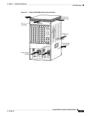
Chapter 2 Preparing for Installation Figure 2-8 Catalyst 6509-NEB Switch Internal Airflow WS-X6408 WS-X6K-SUP2-2GE STATUSSYSTEMCONSOLPEWR MGRMETSET SUPERVISOR2 WS-X6K-SUP2-2GE STATUSSYSTEMCONSOLPEWR MGRMETSET SUPERVISOR2 1 CONSOLE CONSOLE CONSOLE ...LINK 4 LINK LINK 4 LINK 5 LINK LINK 5 LINK 6 LINK LINK 6 LINK 7 LINK LINK 7 LINK 8 LINK LINK 8 LINK PCMCIA PCMCIA 4 EJECT EJECT 5 Switch Load 100% 1% Switch Load 100% 1% 6 PORT 1 LINK PORT 1 LINK 7 PORT 2 LINK PORT 2 LINK 8 Site Requirements Module air exhaust (3x) Module air inlet Power supply air exhaust...
Chapter 2 Preparing for Installation Figure 2-8 Catalyst 6509-NEB Switch Internal Airflow WS-X6408 WS-X6K-SUP2-2GE STATUSSYSTEMCONSOLPEWR MGRMETSET SUPERVISOR2 WS-X6K-SUP2-2GE STATUSSYSTEMCONSOLPEWR MGRMETSET SUPERVISOR2 1 CONSOLE CONSOLE CONSOLE ...LINK 4 LINK LINK 4 LINK 5 LINK LINK 5 LINK 6 LINK LINK 6 LINK 7 LINK LINK 7 LINK 8 LINK LINK 8 LINK PCMCIA PCMCIA 4 EJECT EJECT 5 Switch Load 100% 1% Switch Load 100% 1% 6 PORT 1 LINK PORT 1 LINK 7 PORT 2 LINK PORT 2 LINK 8 Site Requirements Module air exhaust (3x) Module air inlet Power supply air exhaust...

Installation Guide
Page 98
...FAIL o o SELECT STATUS ACTIVE NEXT INPUT OK SELECT STATUS ACTIVE Catalyst 6500 Series Switches Installation Guide POWER SUPPLY 1 NEXT Site Requirements Figure 2-9 Catalyst 6509-NEB-A Switch Internal Airflow Module air exhaust WS-X6K-SUP2-2GE STATUSSYSTEMCONSOLPEWR MGRMETSET CONSOLE SUPERVISOR2 ...CONSOLE PORT MODE PCMCIA EJECT LINK Switch Load 100% 1% PORT 1 LINK PORT 2 WS-X6K-SUP2...
...FAIL o o SELECT STATUS ACTIVE NEXT INPUT OK SELECT STATUS ACTIVE Catalyst 6500 Series Switches Installation Guide POWER SUPPLY 1 NEXT Site Requirements Figure 2-9 Catalyst 6509-NEB-A Switch Internal Airflow Module air exhaust WS-X6K-SUP2-2GE STATUSSYSTEMCONSOLPEWR MGRMETSET CONSOLE SUPERVISOR2 ...CONSOLE PORT MODE PCMCIA EJECT LINK Switch Load 100% 1% PORT 1 LINK PORT 2 WS-X6K-SUP2...
Installation Guide
Page 99
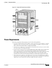
...removed. The 4000 W AC-input power supply power cords are hard-wired to a separate input power source. OL-5781-04 Catalyst 6500 Series Switches Installation Guide 2-19 Please be aware when selecting a UPS that some UPS models that the total maximum load on each source circuit... which use an uninterruptible power supply (UPS) to the site power source. Chapter 2 Preparing for Installation Figure 2-10 Catalyst 6513 Switch Internal Airflow Fan assembly Module air exhaust Fan status LED WS-X6K-SUP2-2GE 1 STATUS SYSTEMCONSOLPEWR MGRMETSET CONSOLE PORT SUPERVISOR2 CONSOLE MODE WS...
...removed. The 4000 W AC-input power supply power cords are hard-wired to a separate input power source. OL-5781-04 Catalyst 6500 Series Switches Installation Guide 2-19 Please be aware when selecting a UPS that some UPS models that the total maximum load on each source circuit... which use an uninterruptible power supply (UPS) to the site power source. Chapter 2 Preparing for Installation Figure 2-10 Catalyst 6513 Switch Internal Airflow Fan assembly Module air exhaust Fan status LED WS-X6K-SUP2-2GE 1 STATUS SYSTEMCONSOLPEWR MGRMETSET CONSOLE PORT SUPERVISOR2 CONSOLE MODE WS...