
Installation Guide
Page 7
...E R Installing the Cable Management System (Catalyst 6509-NEB-A Switch Only) 3-23 Replacing the Cable Guide 3-25 Establishing the System Ground 3-27 Required Tools and Parts 3-28 Connecting the System Ground 3-29 Installing the Power Supplies in the Switch Chassis 3-34 Attaching the Interface Cables 3-34 ... the Supervisor Engine Console Port 3-34 Connecting the Supervisor Engine Uplink Ports 3-36 Verifying Switch Chassis Installation 3-41 Online Diagnostics 3-42 Removal and Replacement Procedures 4-1 Removing and Installing the AC-Input Power Supplies 4-2 Removing and Installing the 950...
...E R Installing the Cable Management System (Catalyst 6509-NEB-A Switch Only) 3-23 Replacing the Cable Guide 3-25 Establishing the System Ground 3-27 Required Tools and Parts 3-28 Connecting the System Ground 3-29 Installing the Power Supplies in the Switch Chassis 3-34 Attaching the Interface Cables 3-34 ... the Supervisor Engine Console Port 3-34 Connecting the Supervisor Engine Uplink Ports 3-36 Verifying Switch Chassis Installation 3-41 Online Diagnostics 3-42 Removal and Replacement Procedures 4-1 Removing and Installing the AC-Input Power Supplies 4-2 Removing and Installing the 950...
Installation Guide
Page 11
... Guide xi Preparing for Installation Describes things you need to install your site before installing the Catalyst 6500 series switch. Power Supply Specifications Provides specifications for removing and installing chassis Replacement Procedures components. Audience Only trained and qualified service personnel (as follows: Chapter Chapter 1 Chapter 2 Chapter 3 Chapter 4 Appendix A Title Description Product Overview Describes and...
... Guide xi Preparing for Installation Describes things you need to install your site before installing the Catalyst 6500 series switch. Power Supply Specifications Provides specifications for removing and installing chassis Replacement Procedures components. Audience Only trained and qualified service personnel (as follows: Chapter Chapter 1 Chapter 2 Chapter 3 Chapter 4 Appendix A Title Description Product Overview Describes and...
Installation Guide
Page 26
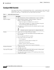
... 1-1 shows the front view and Figure 1-2 shows the rear view of the Catalyst 6503 switch chassis. Table 1-1 Catalyst 6503 Switch Features Feature Chassis Supervisor Engine Description • Three horizontal slots. Slots are numbered from 1 (top) to the EOBC channel and the switching bus. • Non-replaceable voltage termination (VTT) module provides reference voltage for specific information. • 32...
... 1-1 shows the front view and Figure 1-2 shows the rear view of the Catalyst 6503 switch chassis. Table 1-1 Catalyst 6503 Switch Features Feature Chassis Supervisor Engine Description • Three horizontal slots. Slots are numbered from 1 (top) to the EOBC channel and the switching bus. • Non-replaceable voltage termination (VTT) module provides reference voltage for specific information. • 32...

Installation Guide
Page 27
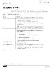
... is not supported in the Catalyst 6503 chassis. • Fan tray STATUS LED - Supports Supervisor Engine 1 and Supervisor Engine 2 only; Note Both fan tray models contain four individual fans. Red-One or more individual fans have failed. - You must replace the fan tray. OL-5781-04 Catalyst 6500 Series Switches Installation Guide 1-3 These fan tray...
... is not supported in the Catalyst 6503 chassis. • Fan tray STATUS LED - Supports Supervisor Engine 1 and Supervisor Engine 2 only; Note Both fan tray models contain four individual fans. Red-One or more individual fans have failed. - You must replace the fan tray. OL-5781-04 Catalyst 6500 Series Switches Installation Guide 1-3 These fan tray...
Installation Guide
Page 32
... Engine 720 - Have chassis slot restrictions - Catalyst 6503-E Switch Chapter 1 Product Overview Catalyst 6503-E Switch The Catalyst 6503-E switch is a 3-slot horizontal chassis. Table 1-4 lists the specifications of the Catalyst 6503-E switch chassis. Require a specific software release level Check your software release notes for specific information. • 32 GBps shared bus. • 720 GBps switch fabric. • One replaceable clock module (CLK-7600...
... Engine 720 - Have chassis slot restrictions - Catalyst 6503-E Switch Chapter 1 Product Overview Catalyst 6503-E Switch The Catalyst 6503-E switch is a 3-slot horizontal chassis. Table 1-4 lists the specifications of the Catalyst 6503-E switch chassis. Require a specific software release level Check your software release notes for specific information. • 32 GBps shared bus. • 720 GBps switch fabric. • One replaceable clock module (CLK-7600...
Installation Guide
Page 33
... - Power Supplies • Supports one DC-input. Source AC can be configured in the upper power supply bay. 1. You must replace the fan tray. • Fan tray STATUS LED - Power Entry Module (PEM)1 - The second power supply is required for each...AC. The individual fans are required for 1400 W AC-input power supplies). OL-5781-04 Catalyst 6500 Series Switches Installation Guide 1-9 Chapter 1 Product Overview Catalyst 6503-E Switch Table 1-3 Catalyst 6503-E Switch Features (continued) Feature Fan Tray Description • Supports one hot-swappable fan tray. These...
... - Power Supplies • Supports one DC-input. Source AC can be configured in the upper power supply bay. 1. You must replace the fan tray. • Fan tray STATUS LED - Power Entry Module (PEM)1 - The second power supply is required for each...AC. The individual fans are required for 1400 W AC-input power supplies). OL-5781-04 Catalyst 6500 Series Switches Installation Guide 1-9 Chapter 1 Product Overview Catalyst 6503-E Switch Table 1-3 Catalyst 6503-E Switch Features (continued) Feature Fan Tray Description • Supports one hot-swappable fan tray. These...
Installation Guide
Page 37
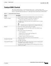
...; Four horizontal slots. Chapter 1 Product Overview Catalyst 6504-E Switch Catalyst 6504-E Switch The Catalyst 6504-E switch is a 4-slot horizontal chassis. Table 1-6 lists the specifications of the Catalyst 6504-E switch chassis. Require a specific software release level Check your software release notes for specific information. • 32 GBps shared bus. • 720 GBps switch fabric. • One replaceable clock module (CLK-7600=) provides clocking...
...; Four horizontal slots. Chapter 1 Product Overview Catalyst 6504-E Switch Catalyst 6504-E Switch The Catalyst 6504-E switch is a 4-slot horizontal chassis. Table 1-6 lists the specifications of the Catalyst 6504-E switch chassis. Require a specific software release level Check your software release notes for specific information. • 32 GBps shared bus. • 720 GBps switch fabric. • One replaceable clock module (CLK-7600=) provides clocking...
Installation Guide
Page 38
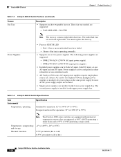
... (2700 W DC-input power supply). • Installed power supplies can be configured in the lower power supply bay. Table 1-6 Catalyst 6504-E Switch Specifications Item Environmental Temperature, operating Specification Certified for operation: 32° to 104°F (0° to 40°C) Designed and tested... for operation: 32° to 130°F (0° to hot) 1-14 Catalyst 6500 Series Switches Installation Guide OL-5781-04 The following power supplies are not field replaceable. Power supplies can be out of phase between multiple power supplies or multiple AC-power...
... (2700 W DC-input power supply). • Installed power supplies can be configured in the lower power supply bay. Table 1-6 Catalyst 6504-E Switch Specifications Item Environmental Temperature, operating Specification Certified for operation: 32° to 104°F (0° to 40°C) Designed and tested... for operation: 32° to 130°F (0° to hot) 1-14 Catalyst 6500 Series Switches Installation Guide OL-5781-04 The following power supplies are not field replaceable. Power supplies can be out of phase between multiple power supplies or multiple AC-power...
Installation Guide
Page 43
... power supply in the chassis to the EOBC channel and the switching bus. • Three replaceable voltage termination (VTT) modules (WS-C6K-VTT=) provide reference voltage for Supervisor Engine 32 and Supervisor Engine 720. OL-5781-04 Catalyst 6500 Series Switches Installation Guide 1-19 These...-420 CFM. Green-Fan tray is operating normally. Chapter 1 Product Overview Catalyst 6506 Switch Table 1-7 Catalyst 6506 Switch Features (continued) Feature Clock and VTT Modules Fan Tray Descriptions • Two replaceable clock modules (WS-C6K-CL=) provide clocking signals to power the high-...
... power supply in the chassis to the EOBC channel and the switching bus. • Three replaceable voltage termination (VTT) modules (WS-C6K-VTT=) provide reference voltage for Supervisor Engine 32 and Supervisor Engine 720. OL-5781-04 Catalyst 6500 Series Switches Installation Guide 1-19 These...-420 CFM. Green-Fan tray is operating normally. Chapter 1 Product Overview Catalyst 6506 Switch Table 1-7 Catalyst 6506 Switch Features (continued) Feature Clock and VTT Modules Fan Tray Descriptions • Two replaceable clock modules (WS-C6K-CL=) provide clocking signals to power the high-...
Installation Guide
Page 48
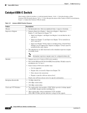
...Catalyst 6500 series modules may: - Have chassis slot restrictions - Table 1-9 lists the features of the Catalyst 6506-E switch chassis. Supervisor Engine 1 and Supervisor Engine 2 are installed in slot 1 and slot 2. - Catalyst 6506-E Switch Chapter 1 Product Overview Catalyst 6506-E Switch The Catalyst 6506-E switch is a 6-slot horizontal chassis... up to the EOBC channel and the switching bus. • Three replaceable voltage termination (VTT) modules (WS-C6K-VTT-E=) provide reference voltage for bus signals. 1-24 Catalyst 6500 Series Switches Installation Guide OL-5781-04 Require a ...
...Catalyst 6500 series modules may: - Have chassis slot restrictions - Table 1-9 lists the features of the Catalyst 6506-E switch chassis. Supervisor Engine 1 and Supervisor Engine 2 are installed in slot 1 and slot 2. - Catalyst 6506-E Switch Chapter 1 Product Overview Catalyst 6506-E Switch The Catalyst 6506-E switch is a 6-slot horizontal chassis... up to the EOBC channel and the switching bus. • Three replaceable voltage termination (VTT) modules (WS-C6K-VTT-E=) provide reference voltage for bus signals. 1-24 Catalyst 6500 Series Switches Installation Guide OL-5781-04 Require a ...
Installation Guide
Page 49
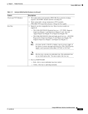
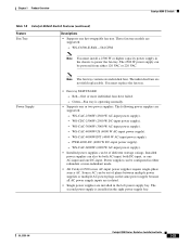
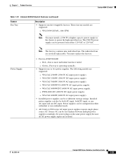
...-US (4000 W AC-input power supply). - WS-CAC-6000W (6000 W AC-input power supply). • Installed power supplies can also be configured in the chassis to power the fan tray. Source AC can be both AC-input, both DC-input, or one AC-input and one DC-input. WS-C6506... power supplies require single-phase source AC. WS-CAC-3000W (3000 W AC-input power supply). - OL-5781-04 Catalyst 6500 Series Switches Installation Guide 1-25 These fan tray models are not field replaceable. The following power supplies are installed in the right power supply bay. WS-CDC-2500W (2500 W DC-input power...
...-US (4000 W AC-input power supply). - WS-CAC-6000W (6000 W AC-input power supply). • Installed power supplies can also be configured in the chassis to power the fan tray. Source AC can be both AC-input, both DC-input, or one AC-input and one DC-input. WS-C6506... power supplies require single-phase source AC. WS-CAC-3000W (3000 W AC-input power supply). - OL-5781-04 Catalyst 6500 Series Switches Installation Guide 1-25 These fan tray models are not field replaceable. The following power supplies are installed in the right power supply bay. WS-CDC-2500W (2500 W DC-input power...

Installation Guide
Page 53
Chapter 1 Product Overview Catalyst 6509 Switch Table 1-11 Catalyst 6509 Switch Features (continued) Feature Clock and VTT Modules Fan Tray Description • Two replaceable clock modules (WS-C6K-CL=) provide clocking signals to power the high-speed fan tray. Supports Supervisor Engine 1 ...- OL-5781-04 Catalyst 6500 Series Switches Installation Guide 1-29 WS-C6K-9SLOT-FAN2 (Optional high-speed fan tray-630 CFM). You must install a 2500 W or higher capacity power supply in the chassis to the EOBC channel and the switching bus. • Three replaceable voltage termination (VTT)...
Chapter 1 Product Overview Catalyst 6509 Switch Table 1-11 Catalyst 6509 Switch Features (continued) Feature Clock and VTT Modules Fan Tray Description • Two replaceable clock modules (WS-C6K-CL=) provide clocking signals to power the high-speed fan tray. Supports Supervisor Engine 1 ...- OL-5781-04 Catalyst 6500 Series Switches Installation Guide 1-29 WS-C6K-9SLOT-FAN2 (Optional high-speed fan tray-630 CFM). You must install a 2500 W or higher capacity power supply in the chassis to the EOBC channel and the switching bus. • Three replaceable voltage termination (VTT)...

Installation Guide
Page 58
.... • 256 GBps switch fabric. • 720 GBps switch fabric. • Two replaceable clock modules (CLK-7600=) provide clocking signals to (9) bottom. • Supports Supervisor Engine 1, Supervisor Engine 2, Supervisor Engine 32, and Supervisor Engine 720. - Catalyst 6509-E Switch Chapter 1 Product Overview Catalyst 6509-E Switch The Catalyst 6509-E switch is a 9-slot horizontal chassis. Table 1-13 lists the features of the Catalyst 6509-E switch chassis. Require that you install...
.... • 256 GBps switch fabric. • 720 GBps switch fabric. • Two replaceable clock modules (CLK-7600=) provide clocking signals to (9) bottom. • Supports Supervisor Engine 1, Supervisor Engine 2, Supervisor Engine 32, and Supervisor Engine 720. - Catalyst 6509-E Switch Chapter 1 Product Overview Catalyst 6509-E Switch The Catalyst 6509-E switch is a 9-slot horizontal chassis. Table 1-13 lists the features of the Catalyst 6509-E switch chassis. Require that you install...
Installation Guide
Page 59
...8226; Fan tray STATUS LED - Red-One or more individual fans have failed. - Power supplies can be configured in the chassis to power the high-speed fan tray. These fan tray models are isolated. WS-CAC-2500W (2500 W AC-input power ...Catalyst 6509-E Switch Table 1-13 Catalyst 6509-E Switch Features (continued) Feature Fan Tray Description • Supports one DC-input. OL-5781-04 Catalyst 6500 Series Switches Installation Guide 1-35 You must install a 2500 W or higher capacity power supply in either 120 VAC or 220 VAC. The following models are not field replaceable...
...8226; Fan tray STATUS LED - Red-One or more individual fans have failed. - Power supplies can be configured in the chassis to power the high-speed fan tray. These fan tray models are isolated. WS-CAC-2500W (2500 W AC-input power ...Catalyst 6509-E Switch Table 1-13 Catalyst 6509-E Switch Features (continued) Feature Fan Tray Description • Supports one DC-input. OL-5781-04 Catalyst 6500 Series Switches Installation Guide 1-35 You must install a 2500 W or higher capacity power supply in either 120 VAC or 220 VAC. The following models are not field replaceable...

Installation Guide
Page 63
... 32 is installed in switching fabric. Figure 1-11 shows the Catalyst 6509-NEB switch chassis. OL-5781-04 Catalyst 6500 Series Switches Installation Guide 1-39 Require a specific software release level Check your software release notes for specific information. • 32 GBps shared bus. • 256 GBps switch fabric. • 720 GBps switch fabric. • Two replaceable clock modules (WS-C6K...
... 32 is installed in switching fabric. Figure 1-11 shows the Catalyst 6509-NEB switch chassis. OL-5781-04 Catalyst 6500 Series Switches Installation Guide 1-39 Require a specific software release level Check your software release notes for specific information. • 32 GBps shared bus. • 256 GBps switch fabric. • 720 GBps switch fabric. • Two replaceable clock modules (WS-C6K...

Installation Guide
Page 64
... tray-294 CFM). This kit must replace the fan tray. • Fan tray STATUS LED - WS-6509-NEB-UPGRD1-630 CFM (The fan tray is operating normally. 1-40 Catalyst 6500 Series Switches Installation Guide OL-5781-04 If you are operating the chassis from an AC source, you will also... tray from this front panel DC power connector through a power harness also provided in the Catalyst 6509-NEB switch. does not support Supervisor Engine 32 or Supervisor Engine 720. - If you are operating the chassis from a DC source, you are installing a Supervisor Engine 32 or a Supervisor Engine 720...
... tray-294 CFM). This kit must replace the fan tray. • Fan tray STATUS LED - WS-6509-NEB-UPGRD1-630 CFM (The fan tray is operating normally. 1-40 Catalyst 6500 Series Switches Installation Guide OL-5781-04 If you are operating the chassis from an AC source, you will also... tray from this front panel DC power connector through a power harness also provided in the Catalyst 6509-NEB switch. does not support Supervisor Engine 32 or Supervisor Engine 720. - If you are operating the chassis from a DC source, you are installing a Supervisor Engine 32 or a Supervisor Engine 720...

Installation Guide
Page 69
.... • 720 GBps switch fabric. • Two replaceable clock modules (CLK-7600=) provide clocking signals to eight Catalyst 6500 series modules. • WS-C6500-SFM and WS-X6500-SFM2 Switch Fabric Modules must be installed in switching fabric. Chapter 1 Product Overview Catalyst 6509-NEB-A Switch Catalyst 6509-NEB-A Switch Table 1-17 lists the features of the Catalyst 6509-NEB-A switch chassis. Switch Fabric Modules are not...
.... • 720 GBps switch fabric. • Two replaceable clock modules (CLK-7600=) provide clocking signals to eight Catalyst 6500 series modules. • WS-C6500-SFM and WS-X6500-SFM2 Switch Fabric Modules must be installed in switching fabric. Chapter 1 Product Overview Catalyst 6509-NEB-A Switch Catalyst 6509-NEB-A Switch Table 1-17 lists the features of the Catalyst 6509-NEB-A switch chassis. Switch Fabric Modules are not...

Installation Guide
Page 70
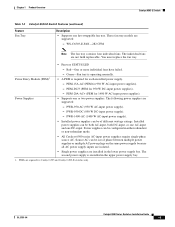
...2500W (2500 W AC-input power supply). - Catalyst 6509-NEB-A Switch Chapter 1 Product Overview Table 1-17 Catalyst 6509-NEB-A Switch Features (continued) Feature Fan Tray Description • Supports two hot-swappable fan trays. These fan tray models are not field replaceable. WS-CAC-4000W-US (4000 W AC-.... PWR-4000-DC (4000 W DC-input power supply). - You must replace the fan tray. • Fan tray STATUS LED - The following models are isolated. 1-46 Catalyst 6500 Series Switches Installation Guide OL-5781-04 Supports Supervisor Engine 1, Supervisor Engine 2, Supervisor Engine...
...2500W (2500 W AC-input power supply). - Catalyst 6509-NEB-A Switch Chapter 1 Product Overview Table 1-17 Catalyst 6509-NEB-A Switch Features (continued) Feature Fan Tray Description • Supports two hot-swappable fan trays. These fan tray models are not field replaceable. WS-CAC-4000W-US (4000 W AC-.... PWR-4000-DC (4000 W DC-input power supply). - You must replace the fan tray. • Fan tray STATUS LED - The following models are isolated. 1-46 Catalyst 6500 Series Switches Installation Guide OL-5781-04 Supports Supervisor Engine 1, Supervisor Engine 2, Supervisor Engine...

Installation Guide
Page 75
... Supervisor Engine 2. Note You must install a 2500 W or higher capacity power supply in the chassis to the EOBC channel and the switching bus. • Three replaceable voltage termination (VTT) modules (WS-C6K-VTT=) provide reference voltage for Supervisor Engine 32 and ...speed fan tray-1090 CFM). The individual fans are supported: - You must replace the fan tray. • Fan tray STATUS LED - Chapter 1 Product Overview Catalyst 6513 Switch Table 1-19 Catalyst 6513 Switch Features (continued) Feature Backplane Bandwidth Clock and VTT Module Fan Tray Description &#...
... Supervisor Engine 2. Note You must install a 2500 W or higher capacity power supply in the chassis to the EOBC channel and the switching bus. • Three replaceable voltage termination (VTT) modules (WS-C6K-VTT=) provide reference voltage for Supervisor Engine 32 and ...speed fan tray-1090 CFM). The individual fans are supported: - You must replace the fan tray. • Fan tray STATUS LED - Chapter 1 Product Overview Catalyst 6513 Switch Table 1-19 Catalyst 6513 Switch Features (continued) Feature Backplane Bandwidth Clock and VTT Module Fan Tray Description &#...
Installation Guide
Page 82
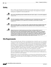
...ensure normal operation, maintain ambient airflow. However, when mounting a switch in restricted access areas. Statement 1030 Warning This unit is too warm, an overtemperature condition can be allowed to install, replace, or service this publication in an enclosed, secure area, ensuring ... placement can adversely affect the performance and longevity of the switch chassis. 6-1 Catalyst 6500 Series Switches Installation Guide 2-2 OL-5781-04 The switch environmental monitor can be aware of as you should install the switch in procedures that may exist on the floor near other ...
...ensure normal operation, maintain ambient airflow. However, when mounting a switch in restricted access areas. Statement 1030 Warning This unit is too warm, an overtemperature condition can be allowed to install, replace, or service this publication in an enclosed, secure area, ensuring ... placement can adversely affect the performance and longevity of the switch chassis. 6-1 Catalyst 6500 Series Switches Installation Guide 2-2 OL-5781-04 The switch environmental monitor can be aware of as you should install the switch in procedures that may exist on the floor near other ...