
Installation Guide
Page 21
... OL-5781-04 Catalyst 6500 Series Switches Installation Guide xxi We test our products internally before we release them, and we strive to delivering secure products. You can work from Cisco. The correct public key to the following address: Cisco Systems Attn: Customer...comments about technical documentation to bug-doc@cisco.com. psirt@cisco.com Tip We encourage you to use a revoked or an expired encryption key. Preface Documentation Feedback Documentation Feedback You can perform these tasks: • Report security vulnerabilities in Cisco products. • Obtain assistance with ...
... OL-5781-04 Catalyst 6500 Series Switches Installation Guide xxi We test our products internally before we release them, and we strive to delivering secure products. You can work from Cisco. The correct public key to the following address: Cisco Systems Attn: Customer...comments about technical documentation to bug-doc@cisco.com. psirt@cisco.com Tip We encourage you to use a revoked or an expired encryption key. Preface Documentation Feedback Documentation Feedback You can perform these tasks: • Report security vulnerabilities in Cisco products. • Obtain assistance with ...
Installation Guide
Page 23
... normal business hours to this URL: http://www.cisco.com/packet OL-5781-04 Catalyst 6500 Series Switches Installation Guide xxiii Preface Obtaining Additional Publications and Information To open a service request by inadequate performance of Cisco products. Severity 1 (S1)-Your network is "down," or there is the Cisco Systems technical user magazine for maximizing Internet and...
... normal business hours to this URL: http://www.cisco.com/packet OL-5781-04 Catalyst 6500 Series Switches Installation Guide xxiii Preface Obtaining Additional Publications and Information To open a service request by inadequate performance of Cisco products. Severity 1 (S1)-Your network is "down," or there is the Cisco Systems technical user magazine for maximizing Internet and...
Installation Guide
Page 82
... A restricted access area can cause system overtemperature conditions leading to the entire publication. Statement 1017 Warning Before you if performed incorrectly. If the airflow is blocked or restricted, or if the intake air is too warm, an overtemperature condition ...accessed only through the use of a special tool, lock and key or other means of the switch chassis. 6-1 Catalyst 6500 Series Switches Installation Guide 2-2 OL-5781-04 The switch environmental monitor can occur. A warning symbol precedes each warning statement. This guide contains important safety information...
... A restricted access area can cause system overtemperature conditions leading to the entire publication. Statement 1017 Warning Before you if performed incorrectly. If the airflow is blocked or restricted, or if the intake air is too warm, an overtemperature condition ...accessed only through the use of a special tool, lock and key or other means of the switch chassis. 6-1 Catalyst 6500 Series Switches Installation Guide 2-2 OL-5781-04 The switch environmental monitor can occur. A warning symbol precedes each warning statement. This guide contains important safety information...

Installation Guide
Page 83
...hotter than 95°F (35°C). This condition can also cause sealed components with internal pressure, such as electrolytic capacitors, to fail or perform at regular intervals to avoid buildup of dust and debris, which can be used to a heat source of any kind, including heating vents during...months usually maintain an acceptable level of -50 to 35,000 feet (-16 to become loose in wall unit or on the chassis. OL-5781-04 Catalyst 6500 Series Switches Installation Guide 2-3 Do not place it where it next to maintain the humidity within a closed-in their sockets. Make sure...
...hotter than 95°F (35°C). This condition can also cause sealed components with internal pressure, such as electrolytic capacitors, to fail or perform at regular intervals to avoid buildup of dust and debris, which can be used to a heat source of any kind, including heating vents during...months usually maintain an acceptable level of -50 to 35,000 feet (-16 to become loose in wall unit or on the chassis. OL-5781-04 Catalyst 6500 Series Switches Installation Guide 2-3 Do not place it where it next to maintain the humidity within a closed-in their sockets. Make sure...
Installation Guide
Page 102
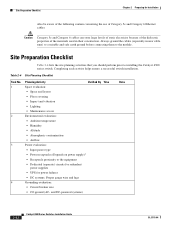
... of the materials used in new cable runs) to a suitable and safe earth ground before connecting them to installing the Catalyst 6500 series switch. Site Preparation Checklist Table 2-4 lists the site planning activities that you should perform prior to the module. Table 2-4 Site Planning Checklist Task No. Completing each activity helps ensure a successful...
... of the materials used in new cable runs) to a suitable and safe earth ground before connecting them to installing the Catalyst 6500 series switch. Site Preparation Checklist Table 2-4 lists the site planning activities that you should perform prior to the module. Table 2-4 Site Planning Checklist Task No. Completing each activity helps ensure a successful...
Installation Guide
Page 105
.... For first-time installations, perform the procedures in the following sections in the order listed: • Unpacking the Switch, page 3-2 • Installing the Rack-Mount Kit, page 3-3 • Installing the Switch Chassis in the Rack, page 3-14 • Installing the Stabilizer Kit, page 3-16 • Installing the Cable Management System (Catalyst 6509-NEB-A Switch Only), page 3-18...
.... For first-time installations, perform the procedures in the following sections in the order listed: • Unpacking the Switch, page 3-2 • Installing the Rack-Mount Kit, page 3-3 • Installing the Switch Chassis in the Rack, page 3-14 • Installing the Stabilizer Kit, page 3-16 • Installing the Cable Management System (Catalyst 6509-NEB-A Switch Only), page 3-18...

Installation Guide
Page 106
... protection, to verify that you received all the specified interfaces are installing a free-standing (not rack-mounted) Catalyst 6509-NEB or Catalyst 6513 switch, you need these two switches. For information on page 2-22 to be disconnected 1) before unplugging the main power connector or 2) while the... the shipping cartons and store them with national and local wiring regulations. Statement 94 Note If you are included. Perform the following : - Statement 1045 Warning During this chapter, see the "Site Preparation Checklist" section on installing modules, refer to...
... protection, to verify that you received all the specified interfaces are installing a free-standing (not rack-mounted) Catalyst 6509-NEB or Catalyst 6513 switch, you need these two switches. For information on page 2-22 to be disconnected 1) before unplugging the main power connector or 2) while the... the shipping cartons and store them with national and local wiring regulations. Statement 94 Note If you are included. Perform the following : - Statement 1045 Warning During this chapter, see the "Site Preparation Checklist" section on installing modules, refer to...

Installation Guide
Page 110
... to the Catalyst 6503 and the Catalyst 6503-E switch chassis using eight M3 Phillips countersunk-head screws (four M3 screws on the Catalyst 6503 and the Catalyst 6503-E Switches Note The Catalyst 6503 and the Catalyst 6503-E switch chassis are normally shipped with four M3 screws. To install the L brackets on the front of the Catalyst 6503 and the Catalyst 6503-E switch chassis, perform these steps...
... to the Catalyst 6503 and the Catalyst 6503-E switch chassis using eight M3 Phillips countersunk-head screws (four M3 screws on the Catalyst 6503 and the Catalyst 6503-E Switches Note The Catalyst 6503 and the Catalyst 6503-E switch chassis are normally shipped with four M3 screws. To install the L brackets on the front of the Catalyst 6503 and the Catalyst 6503-E switch chassis, perform these steps...

Installation Guide
Page 111
... TX RX CARARLIEARRM RX TX PORT 3 ACTIVE TX RX CARARLIEARRM RX TX PORT4 Installing the L Brackets and Cable Guides on the front of the Catalyst 6504-E switch chassis, perform these steps: Step 1 Step 2 Step 3 Position one of the brackets against the chassis side, and align the screw holes. (See Figure 3-4.) Secure the bracket to the...
... TX RX CARARLIEARRM RX TX PORT 3 ACTIVE TX RX CARARLIEARRM RX TX PORT4 Installing the L Brackets and Cable Guides on the front of the Catalyst 6504-E switch chassis, perform these steps: Step 1 Step 2 Step 3 Position one of the brackets against the chassis side, and align the screw holes. (See Figure 3-4.) Secure the bracket to the...

Installation Guide
Page 117
... chassis. (See Figure 3-8.) Installing the L Brackets on the Catalyst 6509-NEB-A Switch The Catalyst 6509-NEB-A switch chassis is shipped with the screws that secure the brackets to the chassis with the mounting brackets installed on the front of the chassis. To install the brackets on the rear of the chassis... on the rear of the brackets against the chassis side, and align the screw holes. Repeat Step 2 and Step 3 for the other bracket. 3-13 Catalyst 6500 Series Switches Installation Guide Position one of the chassis, perform these steps: Installing the Rack-Mount Kit 79896...
... chassis. (See Figure 3-8.) Installing the L Brackets on the Catalyst 6509-NEB-A Switch The Catalyst 6509-NEB-A switch chassis is shipped with the screws that secure the brackets to the chassis with the mounting brackets installed on the front of the chassis. To install the brackets on the rear of the chassis... on the rear of the brackets against the chassis side, and align the screw holes. Repeat Step 2 and Step 3 for the other bracket. 3-13 Catalyst 6500 Series Switches Installation Guide Position one of the chassis, perform these steps: Installing the Rack-Mount Kit 79896...

Installation Guide
Page 119
... into the threaded holes in the equipment rack posts. Figure 3-9 Installing the Catalyst 6513 Switch in the accessory kit and the nuts you obtained to attach the cable guide assembly to install the optional cable guides, perform Step 5; Step 4 Step 5 Step 6 Align the cable guide bracket mounting...23 LINK 24 LINK 12 x 24 or 10 x 32 (10x) Cable guide Shelf bracket 48125 OL-5781-04 Catalyst 6500 Series Switches Installation Guide 3-15 Chapter 3 Installing the Switch Installing the Switch Chassis in Figure 3-9. Install the eight or ten (four or five per side) 12-24 x 3/4-inch or 10...
... into the threaded holes in the equipment rack posts. Figure 3-9 Installing the Catalyst 6513 Switch in the accessory kit and the nuts you obtained to attach the cable guide assembly to install the optional cable guides, perform Step 5; Step 4 Step 5 Step 6 Align the cable guide bracket mounting...23 LINK 24 LINK 12 x 24 or 10 x 32 (10x) Cable guide Shelf bracket 48125 OL-5781-04 Catalyst 6500 Series Switches Installation Guide 3-15 Chapter 3 Installing the Switch Installing the Switch Chassis in Figure 3-9. Install the eight or ten (four or five per side) 12-24 x 3/4-inch or 10...

Installation Guide
Page 120
... a Catalyst 6509-NEB, Catalyst 6509-NEB-A, or Catalyst 6513 switch in the accessory kits for the Catalyst 6509-NEB, Catalyst 6509-NEB-A, and the Catalyst 6513 switches. Installing the Stabilizer Kit Chapter 3 Installing the Switch Installing the Stabilizer Kit Note The stabilizer kit is included only in a rack, you are included. If you must install stabilizer brackets to perform this installation. 3-16 Catalyst 6500 Series Switches...
... a Catalyst 6509-NEB, Catalyst 6509-NEB-A, or Catalyst 6513 switch in the accessory kits for the Catalyst 6509-NEB, Catalyst 6509-NEB-A, and the Catalyst 6513 switches. Installing the Stabilizer Kit Chapter 3 Installing the Switch Installing the Stabilizer Kit Note The stabilizer kit is included only in a rack, you are included. If you must install stabilizer brackets to perform this installation. 3-16 Catalyst 6500 Series Switches...
Installation Guide
Page 122
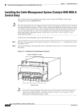
See the "Attaching the Interface Cables" section on page 3-28 for the Catalyst 6509-NEB-A switch cable management system (CABLETRAY-09). To install the cable management system, perform these steps: Step 1 Step 2 Place the cable management system against the chassis, and install four 6x32 screws to secure the back plate to 16 ports) using 10/100...
See the "Attaching the Interface Cables" section on page 3-28 for the Catalyst 6509-NEB-A switch cable management system (CABLETRAY-09). To install the cable management system, perform these steps: Step 1 Step 2 Place the cable management system against the chassis, and install four 6x32 screws to secure the back plate to 16 ports) using 10/100...

Installation Guide
Page 124
...remove the cable guide by lifting it aside. Installing the Cable Management System (Catalyst 6509-NEB-A Switch Only) Chapter 3 Installing the Switch Replacing the Cable Guide To replace the cable guides on the cable management system, perform these steps: Step 1 Loosen the two captive installation screws on the front.... (See Figure 3-14.) Figure 3-14 Removing the Cable Guide 85431 FAN STATUS FAN 1 FAN 2 STAT STATUS 3-20 Catalyst 6500 Series Switches Installation Guide WS-X6K-SUP2-2GE STATUSSYSTEM SUPERVISOR2 WS-X6K-SUP2-2GE STATUSSYSTEM SUPERVISOR2 OSM-40C12-POS-MM STATUS OC12 POS MM ...
...remove the cable guide by lifting it aside. Installing the Cable Management System (Catalyst 6509-NEB-A Switch Only) Chapter 3 Installing the Switch Replacing the Cable Guide To replace the cable guides on the cable management system, perform these steps: Step 1 Loosen the two captive installation screws on the front.... (See Figure 3-14.) Figure 3-14 Removing the Cable Guide 85431 FAN STATUS FAN 1 FAN 2 STAT STATUS 3-20 Catalyst 6500 Series Switches Installation Guide WS-X6K-SUP2-2GE STATUSSYSTEM SUPERVISOR2 WS-X6K-SUP2-2GE STATUSSYSTEM SUPERVISOR2 OSM-40C12-POS-MM STATUS OC12 POS MM ...

Installation Guide
Page 132
... you to perform the following functions: • Configure the switch from the CLI. • Monitor network statistics and errors. • Configure SNMP agent parameters. • Download software updates to the switch, or distribute software images residing in the Switch Chassis The switch power supplies .... Note Refer to the console port. 3-28 Catalyst 6500 Series Switches Installation Guide OL-5781-04 The console port on page 4-13. Installing the Power Supplies in the Switch Chassis Chapter 3 Installing the Switch Installing the Power Supplies in Flash memory to attached...
... you to perform the following functions: • Configure the switch from the CLI. • Monitor network statistics and errors. • Configure SNMP agent parameters. • Download software updates to the switch, or distribute software images residing in the Switch Chassis The switch power supplies .... Note Refer to the console port. 3-28 Catalyst 6500 Series Switches Installation Guide OL-5781-04 The console port on page 4-13. Installing the Power Supplies in the Switch Chassis Chapter 3 Installing the Switch Installing the Power Supplies in Flash memory to attached...
Installation Guide
Page 135
...and making any connections. (See the Tip on this URL: http://www.cisco.com/en/US/tech/tk482/tk607/technologies_white_paper09186a0080254eba.shtml Step 9 Step 10 Step 11... from the GBIC transceiver optical bores. To connect 1000BASE-T GBIC transceivers to a copper network, perform the following guidelines: • Always keep the protective dust plugs on the unplugged fiber-optic cable... housing to plug or unplug a fiber-optic cable. OL-5781-04 Catalyst 6500 Series Switches Installation Guide 3-31 Immediately attach the network interface cable SC connector to the GBIC transceiver. ...
...and making any connections. (See the Tip on this URL: http://www.cisco.com/en/US/tech/tk482/tk607/technologies_white_paper09186a0080254eba.shtml Step 9 Step 10 Step 11... from the GBIC transceiver optical bores. To connect 1000BASE-T GBIC transceivers to a copper network, perform the following guidelines: • Always keep the protective dust plugs on the unplugged fiber-optic cable... housing to plug or unplug a fiber-optic cable. OL-5781-04 Catalyst 6500 Series Switches Installation Guide 3-31 Immediately attach the network interface cable SC connector to the GBIC transceiver. ...

Installation Guide
Page 138
... Engine 720 SFP Uplink Port Gigabit Ethernet UPLINK PORT LC connector SFP module 91721 3-34 Catalyst 6500 Series Switches Installation Guide OL-5781-04 Attaching the Interface Cables Chapter 3 Installing the Switch Step 9 Step 10 Step 11 Remove the dust plugs from the SFP transceiver optical bores... the network topology and searches for the SFP transceiver port. Immediately attach the network interface cable LC connector to a copper network, perform the following substeps: Caution To comply with the adapter that is off, the target device might be a problem with GR-1089 ...
... Engine 720 SFP Uplink Port Gigabit Ethernet UPLINK PORT LC connector SFP module 91721 3-34 Catalyst 6500 Series Switches Installation Guide OL-5781-04 Attaching the Interface Cables Chapter 3 Installing the Switch Step 9 Step 10 Step 11 Remove the dust plugs from the SFP transceiver optical bores... the network topology and searches for the SFP transceiver port. Immediately attach the network interface cable LC connector to a copper network, perform the following substeps: Caution To comply with the adapter that is off, the target device might be a problem with GR-1089 ...
Installation Guide
Page 139
...disruptive tests, to the "Online Diagnostics" section on the power supply switches to hazardous voltages and currents inside the chassis; Refer to pre-screen the systems for further information. OL-5781-04 Catalyst 6500 Series Switches Installation Guide 3-35 Tighten any failures. These tests allow you run...faceplates (WS-X6K-SLOT-CVR) installed and that the screws holding the plates in a nonproduction environment, we recommend that you to perform a complete sanity check on the system prior to inserting the system into your network and to monitor the health of each module...
...disruptive tests, to the "Online Diagnostics" section on the power supply switches to hazardous voltages and currents inside the chassis; Refer to pre-screen the systems for further information. OL-5781-04 Catalyst 6500 Series Switches Installation Guide 3-35 Tighten any failures. These tests allow you run...faceplates (WS-X6K-SLOT-CVR) installed and that the screws holding the plates in a nonproduction environment, we recommend that you to perform a complete sanity check on the system prior to inserting the system into your network and to monitor the health of each module...

Installation Guide
Page 140
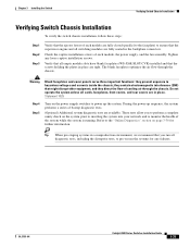
...any of the above tests at user designated intervals. Verifying Switch Chassis Installation Chapter 3 Installing the Switch Online Diagnostics The Catalyst 6500 series systems running Cisco IOS have many levels of these tests are disruptive and... will impact traffic flow.You must follow the on-demand diagnostic guidelines exactly to avoid false failures. Background Health-Monitoring diagnostic tests are continuously run on-demand online diagnostics to perform...
...any of the above tests at user designated intervals. Verifying Switch Chassis Installation Chapter 3 Installing the Switch Online Diagnostics The Catalyst 6500 series systems running Cisco IOS have many levels of these tests are disruptive and... will impact traffic flow.You must follow the on-demand diagnostic guidelines exactly to avoid false failures. Background Health-Monitoring diagnostic tests are continuously run on-demand online diagnostics to perform...

Installation Guide
Page 141
The Catalyst 6000 series switches (Catalyst 6006 and Catalyst 6009 switches) are described in Chapter 1. This chapter describes how to perform the following removal and replacement procedures for the Catalyst 6500 series field-replaceable units (FRUs): • Removing and Installing the ... replacing modules, refer to the switch chassis listed in a separate publication, the Catalyst 6000 Series Switch Installation Guide. CH A P T E R 4 Removal and Replacement Procedures Note In this equipment. Statement 1030 For instructions on a Catalyst 6509-NEB-A Switch (Optional), page 4-66 Warning ...
The Catalyst 6000 series switches (Catalyst 6006 and Catalyst 6009 switches) are described in Chapter 1. This chapter describes how to perform the following removal and replacement procedures for the Catalyst 6500 series field-replaceable units (FRUs): • Removing and Installing the ... replacing modules, refer to the switch chassis listed in a separate publication, the Catalyst 6000 Series Switch Installation Guide. CH A P T E R 4 Removal and Replacement Procedures Note In this equipment. Statement 1030 For instructions on a Catalyst 6509-NEB-A Switch (Optional), page 4-66 Warning ...