
Installation Guide
Page 6
... Installing the L Brackets and Cable Guides on the Catalyst 6506 and Catalyst 6506-E Switches 3-11 Installing the L Brackets and Cable Guides on the Catalyst 6509 and Catalyst 6509-E Switches 3-13 Installing the L Brackets and Cable Guides on the Catalyst 6509-NEB Switch 3-15 Installing the L Brackets on the Catalyst 6509-NEB-A Switch 3-17 Installing the Switch Chassis in the Rack 3-18 Installing the Stabilizer Bracket Kit...
... Installing the L Brackets and Cable Guides on the Catalyst 6506 and Catalyst 6506-E Switches 3-11 Installing the L Brackets and Cable Guides on the Catalyst 6509 and Catalyst 6509-E Switches 3-13 Installing the L Brackets and Cable Guides on the Catalyst 6509-NEB Switch 3-15 Installing the L Brackets on the Catalyst 6509-NEB-A Switch 3-17 Installing the Switch Chassis in the Rack 3-18 Installing the Stabilizer Bracket Kit...
Installation Guide
Page 7
...C H A P T E R Installing the Cable Management System (Catalyst 6509-NEB-A Switch Only) 3-23 Replacing the Cable Guide 3-25 Establishing the System Ground 3-27 Required Tools and Parts 3-28 Connecting the System Ground 3-29 Installing the Power Supplies in the Switch Chassis 3-34 Attaching the Interface Cables 3-34 Connecting the Supervisor Engine Console Port... the Fan Assembly 4-57 Installing the Fan Assembly 4-65 Checking the Installation 4-65 Installing the Air Filter Assembly on a Catalyst 6509-NEB-A Switch (Optional) 4-66 OL-5781-04 Catalyst 6500 Series Switches Installation Guide vii
...C H A P T E R Installing the Cable Management System (Catalyst 6509-NEB-A Switch Only) 3-23 Replacing the Cable Guide 3-25 Establishing the System Ground 3-27 Required Tools and Parts 3-28 Connecting the System Ground 3-29 Installing the Power Supplies in the Switch Chassis 3-34 Attaching the Interface Cables 3-34 Connecting the Supervisor Engine Console Port... the Fan Assembly 4-57 Installing the Fan Assembly 4-65 Checking the Installation 4-65 Installing the Air Filter Assembly on a Catalyst 6509-NEB-A Switch (Optional) 4-66 OL-5781-04 Catalyst 6500 Series Switches Installation Guide vii

Installation Guide
Page 9
...Connector (WS-X6624-FXS Only) B-21 SC Connector B-22 MT-RJ Connector B-22 LC Connector B-23 Cables B-24 Console Port Mode Switch B-26 Identifying a Rollover Cable B-26 Console Port Mode 1 Signaling and Pinouts B-27 Console Port Mode 2 Signaling and Pinouts B-28 ...Mode-Conditioning Patch Cord B-29 Cleaning the Fiber Optic Connectors B-31 Repacking the Switch C-1 Chassis and Module Power and Heat Values D-1 Troubleshooting E-1 Getting Started E-1 Solving Problems at the System Component Level E-2 Identifying Startup Problems E-3 ...
...Connector (WS-X6624-FXS Only) B-21 SC Connector B-22 MT-RJ Connector B-22 LC Connector B-23 Cables B-24 Console Port Mode Switch B-26 Identifying a Rollover Cable B-26 Console Port Mode 1 Signaling and Pinouts B-27 Console Port Mode 2 Signaling and Pinouts B-28 ...Mode-Conditioning Patch Cord B-29 Cleaning the Fiber Optic Connectors B-31 Repacking the Switch C-1 Chassis and Module Power and Heat Values D-1 Troubleshooting E-1 Getting Started E-1 Solving Problems at the System Component Level E-2 Identifying Startup Problems E-3 ...
Installation Guide
Page 11
... cords. Power Supply Specifications Provides specifications for removing and installing chassis Replacement Procedures components. OL-5781-04 Catalyst 6500 Series Switches Installation Guide xi Organization This publication is organized, and its document conventions. Installing the Switch Describes how to consider when preparing your Catalyst 6500 series switch. Preparing for Installation Describes things you need to install...
... cords. Power Supply Specifications Provides specifications for removing and installing chassis Replacement Procedures components. OL-5781-04 Catalyst 6500 Series Switches Installation Guide xi Organization This publication is organized, and its document conventions. Installing the Switch Describes how to consider when preparing your Catalyst 6500 series switch. Preparing for Installation Describes things you need to install...
Installation Guide
Page 12
... quotation marks around the string or the string will include the quotation marks. Catalyst 6500 Series Switches Installation Guide xii OL-5781-04 Alternative keywords are in braces and separated by vertical bars. Provides troubleshooting guidelines for the Catalyst 6500 series switch chassis and modules. Provides listings of the power consumption and heat dissipation values...
... quotation marks around the string or the string will include the quotation marks. Catalyst 6500 Series Switches Installation Guide xii OL-5781-04 Alternative keywords are in braces and separated by vertical bars. Provides troubleshooting guidelines for the Catalyst 6500 series switch chassis and modules. Provides listings of the power consumption and heat dissipation values...
Installation Guide
Page 26
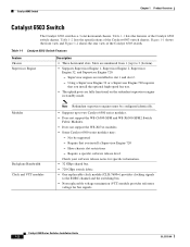
... not support the WS-X67xx modules. • Some Catalyst 6500 series modules may: - Catalyst 6503 Switch Chapter 1 Product Overview Catalyst 6503 Switch The Catalyst 6503 switch is a 3-slot horizontal chassis. Figure 1-1 shows the front view and Figure 1-2 shows the rear view of the Catalyst 6503 switch chassis. Table 1-2 lists the specifications of the Catalyst 6503 switch chassis. Supervisor engines are numbered from 1 (top) to...
... not support the WS-X67xx modules. • Some Catalyst 6500 series modules may: - Catalyst 6503 Switch Chapter 1 Product Overview Catalyst 6503 Switch The Catalyst 6503 switch is a 3-slot horizontal chassis. Figure 1-1 shows the front view and Figure 1-2 shows the rear view of the Catalyst 6503 switch chassis. Table 1-2 lists the specifications of the Catalyst 6503 switch chassis. Supervisor engines are numbered from 1 (top) to...

Installation Guide
Page 27
... or more individual fans have failed. - Note Both fan tray models contain four individual fans. Green-Fan tray is not supported in the Catalyst 6503 chassis. • Fan tray STATUS LED - FAN-MOD-3 (Standard fan tray-170 CFM). Required for Supervisor Engine 32 and Supervisor Engine 720.... You must replace the fan tray. OL-5781-04 Catalyst 6500 Series Switches Installation Guide 1-3 The individual fans are supported: - FAN-MOD-3HS (Optional high...
... or more individual fans have failed. - Note Both fan tray models contain four individual fans. Green-Fan tray is not supported in the Catalyst 6503 chassis. • Fan tray STATUS LED - FAN-MOD-3 (Standard fan tray-170 CFM). Required for Supervisor Engine 32 and Supervisor Engine 720.... You must replace the fan tray. OL-5781-04 Catalyst 6500 Series Switches Installation Guide 1-3 The individual fans are supported: - FAN-MOD-3HS (Optional high...
Installation Guide
Page 28
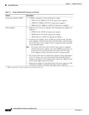
...is required for 950 W AC-input power supplies). - PWR-950-AC (950 W AC-input power supply). - Catalyst 6503 Switch Chapter 1 Product Overview Table 1-1 Catalyst 6503 Switch Features (continued) Feature Power Entry Module (PEM)1 Power Supplies Description • A PEM is installed in the lower power...input power supplies for 950 W DC-input power supplies). - Catalyst 6500 Series Switches Installation Guide 1-4 OL-5781-04 PEM-DC/3 (PEM for these chassis do not have a separate ground. • All Catalyst 6500 series AC-input power supplies require single-phase source AC. ...
...is required for 950 W AC-input power supplies). - PWR-950-AC (950 W AC-input power supply). - Catalyst 6503 Switch Chapter 1 Product Overview Table 1-1 Catalyst 6503 Switch Features (continued) Feature Power Entry Module (PEM)1 Power Supplies Description • A PEM is installed in the lower power...input power supplies for 950 W DC-input power supplies). - Catalyst 6500 Series Switches Installation Guide 1-4 OL-5781-04 PEM-DC/3 (PEM for these chassis do not have a separate ground. • All Catalyst 6500 series AC-input power supplies require single-phase source AC. ...
Installation Guide
Page 30
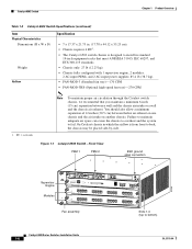
...a minimum separation of 12 inches (30.5 cm) between a wall and the chassis air intake or a wall and the chassis air exhaust. RU = rack units Note To maintain proper air circulation through the Catalyst switch chassis, we recommend that meet ANSI/EIA 310-D, IEC 60297, and ETS 300-119 ...standards. • Chassis only: 27 lb (12.25 kg). • Chassis fully configured with 1 supervisor engine, 2 modules, 2 AC-input PEMs, ...
...a minimum separation of 12 inches (30.5 cm) between a wall and the chassis air intake or a wall and the chassis air exhaust. RU = rack units Note To maintain proper air circulation through the Catalyst switch chassis, we recommend that meet ANSI/EIA 310-D, IEC 60297, and ETS 300-119 ...standards. • Chassis only: 27 lb (12.25 kg). • Chassis fully configured with 1 supervisor engine, 2 modules, 2 AC-input PEMs, ...
Installation Guide
Page 32
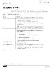
... and Figure 1-4 shows the rear view of the Catalyst 6503-E switch chassis. Table 1-3 Catalyst 6503-E Switch Features Feature Chassis Supervisor Engine Description • Three horizontal slots. Require a specific software release level Check your software release notes for bus signals. Catalyst 6503-E Switch Chapter 1 Product Overview Catalyst 6503-E Switch The Catalyst 6503-E switch is a 3-slot horizontal chassis. Supervisor engines are installed in slot 1 and...
... and Figure 1-4 shows the rear view of the Catalyst 6503-E switch chassis. Table 1-3 Catalyst 6503-E Switch Features Feature Chassis Supervisor Engine Description • Three horizontal slots. Require a specific software release level Check your software release notes for bus signals. Catalyst 6503-E Switch Chapter 1 Product Overview Catalyst 6503-E Switch The Catalyst 6503-E switch is a 3-slot horizontal chassis. Supervisor engines are installed in slot 1 and...
Installation Guide
Page 35
... x 55.25 cm). • Chassis requires 4 RU1. • The Catalyst 6503-E switch chassis is from front to fail. OL-5781-04 Catalyst 6500 Series Switches Installation Guide 1-11 RU = rack units Note To maintain proper air circulation through the Catalyst switch chassis, we recommend that meet ANSI/EIA 310...-D, IEC 60297, and ETS 300-119 standards. • Chassis only: 33 lb (15 kg). • Chassis fully configured with 1 supervisor engine, 2 modules, 2 AC-...
... x 55.25 cm). • Chassis requires 4 RU1. • The Catalyst 6503-E switch chassis is from front to fail. OL-5781-04 Catalyst 6500 Series Switches Installation Guide 1-11 RU = rack units Note To maintain proper air circulation through the Catalyst switch chassis, we recommend that meet ANSI/EIA 310...-D, IEC 60297, and ETS 300-119 standards. • Chassis only: 33 lb (15 kg). • Chassis fully configured with 1 supervisor engine, 2 modules, 2 AC-...
Installation Guide
Page 37
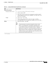
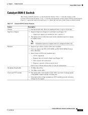
... WS-C6500-SFM and WS-X6500-SFM2 Switch Fabric Modules. • Some Catalyst 6500 series modules may: - Chapter 1 Product Overview Catalyst 6504-E Switch Catalyst 6504-E Switch The Catalyst 6504-E switch is a 4-slot horizontal chassis. Table 1-5 lists the features of the Catalyst 6504-E switch chassis. Table 1-6 lists the specifications of the Catalyst 6504-E switch chassis. Table 1-5 Catalyst 6504-E Switch Features Feature Chassis Supervisor Engine Description • Four horizontal slots...
... WS-C6500-SFM and WS-X6500-SFM2 Switch Fabric Modules. • Some Catalyst 6500 series modules may: - Chapter 1 Product Overview Catalyst 6504-E Switch Catalyst 6504-E Switch The Catalyst 6504-E switch is a 4-slot horizontal chassis. Table 1-5 lists the features of the Catalyst 6504-E switch chassis. Table 1-6 lists the specifications of the Catalyst 6504-E switch chassis. Table 1-5 Catalyst 6504-E Switch Features Feature Chassis Supervisor Engine Description • Four horizontal slots...
Installation Guide
Page 39
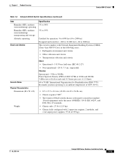
... of 86°F (30°C). • 8.7 x 17.5 x 21.6 in. (22.09 x 44.45 x 54.86 cm). • Chassis requires 5 RU1. • The Catalyst 6504-E switch chassis is designed to install in standard 19-inch equipment racks that meet ANSI/EIA 310-D, IEC 60297, and ETS 300-119 standards. •...; Chassis only: 27 lb (12.25 kg). • Chassis fully configured with Network Equipment Building Systems (NEBS) (Zone 4 per GR-...
... of 86°F (30°C). • 8.7 x 17.5 x 21.6 in. (22.09 x 44.45 x 54.86 cm). • Chassis requires 5 RU1. • The Catalyst 6504-E switch chassis is designed to install in standard 19-inch equipment racks that meet ANSI/EIA 310-D, IEC 60297, and ETS 300-119 standards. •...; Chassis only: 27 lb (12.25 kg). • Chassis fully configured with Network Equipment Building Systems (NEBS) (Zone 4 per GR-...

Installation Guide
Page 40
... Note To maintain proper air circulation through the Catalyst switch chassis, we recommend that you maintain a minimum 6-inch (15 cm) separation between the hot air exhaust on one chassis and the air intake on another chassis. On Catalyst chassis in which the airflow is from front to back, the chassis may be placed side-by-side. You should...
... Note To maintain proper air circulation through the Catalyst switch chassis, we recommend that you maintain a minimum 6-inch (15 cm) separation between the hot air exhaust on one chassis and the air intake on another chassis. On Catalyst chassis in which the airflow is from front to back, the chassis may be placed side-by-side. You should...
Installation Guide
Page 42
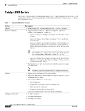
... restrictions - Table 1-7 lists the features of the Catalyst 6506 switch chassis. Supervisor Engine 32 and Supervisor Engine 720 require that you install the high-speed fan tray. Catalyst 6506 Switch Chapter 1 Product Overview Catalyst 6506 Switch The Catalyst 6506 switch is a 6-slot horizontal chassis. Figure 1-7 shows the Catalyst 6506 switch. Slots are installed in switching fabric. Supervisor Engine 1 and Supervisor Engine 2 are numbered...
... restrictions - Table 1-7 lists the features of the Catalyst 6506 switch chassis. Supervisor Engine 32 and Supervisor Engine 720 require that you install the high-speed fan tray. Catalyst 6506 Switch Chapter 1 Product Overview Catalyst 6506 Switch The Catalyst 6506 switch is a 6-slot horizontal chassis. Figure 1-7 shows the Catalyst 6506 switch. Slots are installed in switching fabric. Supervisor Engine 1 and Supervisor Engine 2 are numbered...
Installation Guide
Page 43
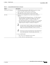
... Engine 32 or Supervisor Engine 720. - You must install a 2500 W or higher capacity power supply in the chassis to the EOBC channel and the switching bus. • Three replaceable voltage termination (VTT) modules (WS-C6K-VTT=) provide reference voltage for Supervisor Engine 32... and Supervisor Engine 720. OL-5781-04 Catalyst 6500 Series Switches Installation Guide 1-19 Supports Supervisor Engine 1 and Supervisor Engine 2.) Note You must replace the fan tray. • Fan tray ...
... Engine 32 or Supervisor Engine 720. - You must install a 2500 W or higher capacity power supply in the chassis to the EOBC channel and the switching bus. • Three replaceable voltage termination (VTT) modules (WS-C6K-VTT=) provide reference voltage for Supervisor Engine 32... and Supervisor Engine 720. OL-5781-04 Catalyst 6500 Series Switches Installation Guide 1-19 Supports Supervisor Engine 1 and Supervisor Engine 2.) Note You must replace the fan tray. • Fan tray ...
Installation Guide
Page 44
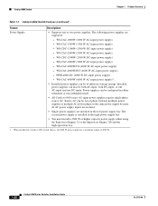
...WS-CAC-6000W (6000 W AC-input power supply)1. • Installed power supplies can also be of 4000 W. 1-20 Catalyst 6500 Series Switches Installation Guide OL-5781-04 WS-CAC-4000W-INT (4000 W AC-input power supply). - The second power supply is installed... installed in the left power supply bay. Catalyst 6506 Switch Chapter 1 Product Overview Table 1-7 Catalyst 6506 Switch Features (continued) Feature Descriptions Power Supply • Supports one DC-input. The following power supplies are installed in a Catalyst 6506 switch chassis, the 6000 W power supply has a maximum...
...WS-CAC-6000W (6000 W AC-input power supply)1. • Installed power supplies can also be of 4000 W. 1-20 Catalyst 6500 Series Switches Installation Guide OL-5781-04 WS-CAC-4000W-INT (4000 W AC-input power supply). - The second power supply is installed... installed in the left power supply bay. Catalyst 6506 Switch Chapter 1 Product Overview Table 1-7 Catalyst 6506 Switch Features (continued) Feature Descriptions Power Supply • Supports one DC-input. The following power supplies are installed in a Catalyst 6506 switch chassis, the 6000 W power supply has a maximum...
Installation Guide
Page 46
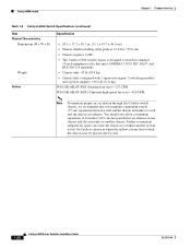
... the system to fail. Note To maintain proper air circulation through the Catalyst switch chassis, we recommend that meet ANSI/EIA 310-D, IEC 60297, and ETS 300-119 standards. • Chassis only: 45 lb (20.4 kg). • Chassis fully configured with 1 supervisor engine, 5 switching modules, and 2 power supplies: 156.6 lb (71.0 kg). WS-C6K-6SLOT-FAN...
... the system to fail. Note To maintain proper air circulation through the Catalyst switch chassis, we recommend that meet ANSI/EIA 310-D, IEC 60297, and ETS 300-119 standards. • Chassis only: 45 lb (20.4 kg). • Chassis fully configured with 1 supervisor engine, 5 switching modules, and 2 power supplies: 156.6 lb (71.0 kg). WS-C6K-6SLOT-FAN...
Installation Guide
Page 48
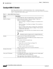
... 720 has built-in slot 5 and slot 6. - Require that you install a Supervisor Engine 720 - Have chassis slot restrictions - Catalyst 6506-E Switch Chapter 1 Product Overview Catalyst 6506-E Switch The Catalyst 6506-E switch is a 6-slot horizontal chassis. Table 1-10 lists the specifications of the Catalyst 6506-E switch chassis. Slots are fully functional on the redundant supervisor engine in standby mode. Figure 1-8 shows the...
... 720 has built-in slot 5 and slot 6. - Require that you install a Supervisor Engine 720 - Have chassis slot restrictions - Catalyst 6506-E Switch Chapter 1 Product Overview Catalyst 6506-E Switch The Catalyst 6506-E switch is a 6-slot horizontal chassis. Table 1-10 lists the specifications of the Catalyst 6506-E switch chassis. Slots are fully functional on the redundant supervisor engine in standby mode. Figure 1-8 shows the...
Installation Guide
Page 49
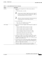
...because all AC power supply inputs are isolated. • Single power supplies are supported: - Green-Fan tray is installed in the chassis to power the fan tray. Red-One or more individual fans have failed. - WS-CAC-2500W (2500 W AC-input power ...W AC-input power supply). • Installed power supplies can be configured in the left power supply bay. Chapter 1 Product Overview Catalyst 6506-E Switch Table 1-9 Catalyst 6506-E Switch Features (continued) Feature Fan Tray Descriptions • Supports one or two power supplies. PWR-4000-DC (4000 W DC-input power ...
...because all AC power supply inputs are isolated. • Single power supplies are supported: - Green-Fan tray is installed in the chassis to power the fan tray. Red-One or more individual fans have failed. - WS-CAC-2500W (2500 W AC-input power ...W AC-input power supply). • Installed power supplies can be configured in the left power supply bay. Chapter 1 Product Overview Catalyst 6506-E Switch Table 1-9 Catalyst 6506-E Switch Features (continued) Feature Fan Tray Descriptions • Supports one or two power supplies. PWR-4000-DC (4000 W DC-input power ...

