
Installation Guide
Page 6
...Frequency Interference 2-4 Shock and Vibration 2-5 Power Source Interruptions 2-5 System Grounding 2-6 Preventing Electrostatic Discharge Damage 2-7 Air Flow 2-10 Power Requirements 2-20 Power Connection Guidelines for AC-Powered Systems 2-21 Power Connection Guidelines for DC-...Catalyst 6506 and Catalyst 6506-E Switches 3-11 Installing the L Brackets and Cable Guides on the Catalyst 6509 and Catalyst 6509-E Switches 3-13 Installing the L Brackets and Cable Guides on the Catalyst 6509-NEB Switch 3-15 Installing the L Brackets on the Catalyst 6509-NEB-A Switch 3-17 Installing the Switch Chassis...
...Frequency Interference 2-4 Shock and Vibration 2-5 Power Source Interruptions 2-5 System Grounding 2-6 Preventing Electrostatic Discharge Damage 2-7 Air Flow 2-10 Power Requirements 2-20 Power Connection Guidelines for AC-Powered Systems 2-21 Power Connection Guidelines for DC-...Catalyst 6506 and Catalyst 6506-E Switches 3-11 Installing the L Brackets and Cable Guides on the Catalyst 6509 and Catalyst 6509-E Switches 3-13 Installing the L Brackets and Cable Guides on the Catalyst 6509-NEB Switch 3-15 Installing the L Brackets on the Catalyst 6509-NEB-A Switch 3-17 Installing the Switch Chassis...

Installation Guide
Page 90
... Installation Air Flow The system fan assembly provides cooling air for the Catalyst 6500 series switches. The Catalyst 6500 series switch is designed to be installed in adjacent racks, you maintain a minimum 6-inch (15 cm) separation between the air intake of one chassis and the hot air exhaust of air available to cool the chassis. To maintain proper air circulation through the Catalyst 6500 switch chassis...
... Installation Air Flow The system fan assembly provides cooling air for the Catalyst 6500 series switches. The Catalyst 6500 series switch is designed to be installed in adjacent racks, you maintain a minimum 6-inch (15 cm) separation between the air intake of one chassis and the hot air exhaust of air available to cool the chassis. To maintain proper air circulation through the Catalyst 6500 switch chassis...

Installation Guide
Page 91
...-9SLOT-FAN2 (high speed) Catalyst 6509-NEB WS-C6509-NEB-FAN - Chapter 2 Preparing for information on page 4-57. OL-5781-04 Catalyst 6500 Series Switches Installation Guide 2-11 Individual fans cannot be replaced. Your Catalyst 6500 series switches currently installed in the rack, the additional heat generated might meet ambient air temperature and air flow requirements now. To replace...
...-9SLOT-FAN2 (high speed) Catalyst 6509-NEB WS-C6509-NEB-FAN - Chapter 2 Preparing for information on page 4-57. OL-5781-04 Catalyst 6500 Series Switches Installation Guide 2-11 Individual fans cannot be replaced. Your Catalyst 6500 series switches currently installed in the rack, the additional heat generated might meet ambient air temperature and air flow requirements now. To replace...
Installation Guide
Page 92
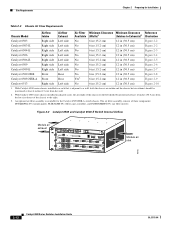
... cage assembly), and FLTRINSERTS-09= (air filter inserts). With Catalyst 6500 series chassis installed in a rack that is available for Installation Table 2-3 Chassis Air Flow Requirements Chassis Model Airflow Intake Airflow Exhaust Air Filter Minimum Clearance Minimum Clearance Reference Available (Walls)1 (Intakes to the right. 3. Figure 2-2 Catalyst 6503 and Catalyst 6503-E Switch Internal Airflow Module air exhaust WS-X6K-SUP2-2GE 1 STATUS...
... cage assembly), and FLTRINSERTS-09= (air filter inserts). With Catalyst 6500 series chassis installed in a rack that is available for Installation Table 2-3 Chassis Air Flow Requirements Chassis Model Airflow Intake Airflow Exhaust Air Filter Minimum Clearance Minimum Clearance Reference Available (Walls)1 (Intakes to the right. 3. Figure 2-2 Catalyst 6503 and Catalyst 6503-E Switch Internal Airflow Module air exhaust WS-X6K-SUP2-2GE 1 STATUS...
Installation Guide
Page 139
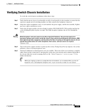
.... During the power-up the system. The blank faceplates optimize the air flow through the chassis. Tip When pre-staging systems in place are tight. Do not operate the system unless all switching modules are available. Refer to hazardous voltages and currents inside the chassis; Tighten any failures. and they contain electromagnetic interference (EMI) that...
.... During the power-up the system. The blank faceplates optimize the air flow through the chassis. Tip When pre-staging systems in place are tight. Do not operate the system unless all switching modules are available. Refer to hazardous voltages and currents inside the chassis; Tighten any failures. and they contain electromagnetic interference (EMI) that...