Installation Guide
Page 4
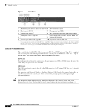
... asynchronous (RJ-45) and USB 5-pin mini Type B, 2.0 compliant serial console ports. EIA/TIA-232 Depending on page 4 for information about downloading the latest Cisco Windows USB Console Driver, refer to 5-pin mini Type B cable. USB Console The USB console port connects directly to the console port. Cisco 5500 Series Wireless Controller Installation Guide 4 78-18998-01 If...
... asynchronous (RJ-45) and USB 5-pin mini Type B, 2.0 compliant serial console ports. EIA/TIA-232 Depending on page 4 for information about downloading the latest Cisco Windows USB Console Driver, refer to 5-pin mini Type B cable. USB Console The USB console port connects directly to the console port. Cisco 5500 Series Wireless Controller Installation Guide 4 78-18998-01 If...

Installation Guide
Page 5
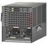
...LED could indicate an error or a possible hardware failure. 78-18998-01 Cisco 5500 Series Wireless Controller Installation Guide 5 Controller Overview With the Cisco Windows USB Console Driver, you can be active at a time. When a cable is not working properly, check the LEDs on the front panel of the... 3 4 1 Power supply PS1 2 Power supply PS1 on/off switch 3 Power supply PS1 AC cable connection 5 4 Power supply PS2 slot with blank cover 5 Fan tray Checking the Controller LEDs If your controller is plugged into the USB console port the RJ-45 port becomes inactive. You can be used.
...LED could indicate an error or a possible hardware failure. 78-18998-01 Cisco 5500 Series Wireless Controller Installation Guide 5 Controller Overview With the Cisco Windows USB Console Driver, you can be active at a time. When a cable is not working properly, check the LEDs on the front panel of the... 3 4 1 Power supply PS1 2 Power supply PS1 on/off switch 3 Power supply PS1 AC cable connection 5 4 Power supply PS2 slot with blank cover 5 Fan tray Checking the Controller LEDs If your controller is plugged into the USB console port the RJ-45 port becomes inactive. You can be used.
Installation Guide
Page 8
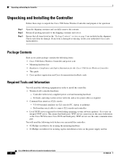
... mounting hardware - Return all items listed in the "Package Contents" section on CLI console (PC, laptop, or palmtop) - If any item is damaged or missing, notify your authorized Cisco sales representative. You will need the following equipment in the shipment. Ensure that third-... screwdriver for operation: Step 1 Step 2 Step 3 Open the shipping container and carefully remove the contents. Cisco uses an integral TFTP server. Null modem serial cable to connect CLI console and controller • Local TFTP server (required for damage. This means that all packing materials to the ...
... mounting hardware - Return all items listed in the "Package Contents" section on CLI console (PC, laptop, or palmtop) - If any item is damaged or missing, notify your authorized Cisco sales representative. You will need the following equipment in the shipment. Ensure that third-... screwdriver for operation: Step 1 Step 2 Step 3 Open the shipping container and carefully remove the contents. Cisco uses an integral TFTP server. Null modem serial cable to connect CLI console and controller • Local TFTP server (required for damage. This means that all packing materials to the ...

Installation Guide
Page 16
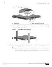
Figure 11 Installing the Cable Guide RP SP USB0 USB1 CONSOLE EN EN Cisco 5500 Series Wireless Controller 12 34 56 78 Model 5508 PS1 PS2 SYS ACT 251240 Installing the Controller in the rack. Statement 1028 Follow these ... brackets to the controller using three M4 screws (see Figure 11). Cisco 5500 Series Wireless Controller Installation Guide 16 78-18998-01 Note We recommend that you attach the cable guide to prevent the cables from obscuring the front panel of the switch and the other devices installed in a 2-Post Rack-Flush Mount Caution...
Figure 11 Installing the Cable Guide RP SP USB0 USB1 CONSOLE EN EN Cisco 5500 Series Wireless Controller 12 34 56 78 Model 5508 PS1 PS2 SYS ACT 251240 Installing the Controller in the rack. Statement 1028 Follow these ... brackets to the controller using three M4 screws (see Figure 11). Cisco 5500 Series Wireless Controller Installation Guide 16 78-18998-01 Note We recommend that you attach the cable guide to prevent the cables from obscuring the front panel of the switch and the other devices installed in a 2-Post Rack-Flush Mount Caution...
Installation Guide
Page 17
... 12 251200 1 Front bracket 2 M4x0.7 x 8mm flat head screws Step 2 Mount the front of the switch and the other devices installed in the Rack RP SP USB0 USB1 CONSOLE EN EN Cisco 5500 Series Wireless Controller 12 34 56 78 Model 5508 PS1 PS2 SYS ACT 274464 Step 3 (Optional) Use... the supplied M4x0.7 x 20mm pan head screw to attach the cable guide to prevent the cables from obscuring the front panel of the controller chassis into the rack...
... 12 251200 1 Front bracket 2 M4x0.7 x 8mm flat head screws Step 2 Mount the front of the switch and the other devices installed in the Rack RP SP USB0 USB1 CONSOLE EN EN Cisco 5500 Series Wireless Controller 12 34 56 78 Model 5508 PS1 PS2 SYS ACT 274464 Step 3 (Optional) Use... the supplied M4x0.7 x 20mm pan head screw to attach the cable guide to prevent the cables from obscuring the front panel of the controller chassis into the rack...

Installation Guide
Page 18
...the unit. Warning This unit might have more people must be removed to the controller using the chassis grounding pad or the provided grounding lug. You will need to the opposite side. Cisco 5500 Series Wireless Controller Installation Guide 18 78-18998-01 Statement 1028 Note When you use the ... than one of the four holes on the chassis (such as the rear bracket mount holes using an M3 screw) using your own grounding lug. Unpacking and Installing the Controller Figure 14 Installing the Cable Guide RP SP USB0 USB1 CONSOLE EN EN Cisco 5500 Series Wireless Controller 12 34 56 78...
...the unit. Warning This unit might have more people must be removed to the controller using the chassis grounding pad or the provided grounding lug. You will need to the opposite side. Cisco 5500 Series Wireless Controller Installation Guide 18 78-18998-01 Statement 1028 Note When you use the ... than one of the four holes on the chassis (such as the rear bracket mount holes using an M3 screw) using your own grounding lug. Unpacking and Installing the Controller Figure 14 Installing the Cable Guide RP SP USB0 USB1 CONSOLE EN EN Cisco 5500 Series Wireless Controller 12 34 56 78...

Installation Guide
Page 20
Caution All power supplies must be made first and disconnected last. The receptacles of the AC power cables used to provide power to the chassis must always be grounded. You will need to protective earth ground at the service equipment. A grounding pad with two threaded M4 holes is already ... unit (RU), install the grounding lug on the right side of the chassis in the wire-up position, or on the left side of Chassis Ground on the Controller (Right Side) 251241 RP SP USB0 USB1 CONSOLE EN EN Cisco 5500 Series Wireless Controller 12 34 56 78 Model 5508 PS1 PS2 SYS...
Caution All power supplies must be made first and disconnected last. The receptacles of the AC power cables used to provide power to the chassis must always be grounded. You will need to protective earth ground at the service equipment. A grounding pad with two threaded M4 holes is already ... unit (RU), install the grounding lug on the right side of the chassis in the wire-up position, or on the left side of Chassis Ground on the Controller (Right Side) 251241 RP SP USB0 USB1 CONSOLE EN EN Cisco 5500 Series Wireless Controller 12 34 56 78 Model 5508 PS1 PS2 SYS...

Installation Guide
Page 21
... the strap to secure the grounding cable in the grounding lug and into the open end of the grounding cable and connect it makes good skin contact. Figure 18 ESD Wrist Strap Connector Location RP SP USB0 USB1 CONSOLE EN EN Cisco 5500 Series Wireless Controller 12 34 ..., and insert the two M4 screws with National Electrical Code (NEC) for the connector location) • Any unpainted surface on the chassis. Prepare the other equipment. Preventing ESD Damage Electrostatic discharge (ESD) damage occurs when electronic cards or components are improperly handled and can result...
... the strap to secure the grounding cable in the grounding lug and into the open end of the grounding cable and connect it makes good skin contact. Figure 18 ESD Wrist Strap Connector Location RP SP USB0 USB1 CONSOLE EN EN Cisco 5500 Series Wireless Controller 12 34 ..., and insert the two M4 screws with National Electrical Code (NEC) for the connector location) • Any unpainted surface on the chassis. Prepare the other equipment. Preventing ESD Damage Electrostatic discharge (ESD) damage occurs when electronic cards or components are improperly handled and can result...
Installation Guide
Page 22
... the controller's RJ-45 console port and the other end of the cable into the back of the controller and connect the other end of the cable into memory, verifies its operating system software load, and initializes itself with its microcode into the PC's USB Type A port. Cisco 5500 Series Wireless Controller Installation Guide...
... the controller's RJ-45 console port and the other end of the cable into the back of the controller and connect the other end of the cable into memory, verifies its operating system software load, and initializes itself with its microcode into the PC's USB Type A port. Cisco 5500 Series Wireless Controller Installation Guide...

