
User Guide
Page 8
...Statements Note: This transmitter must not be installed and operated with Part 2.1091 and Part 15.27. Canada This system has been evaluated for RF exposure for humans in reference to ANSI C 95.1 (American National Standards Institute) limits. US This system has been evaluated for... the radiator and your body. The evaluation was based on the EN 50385 Product Standard to 40 GHz. EU This system has been evaluated for RF exposure for humans as referenced in reference to general bystander is 20 cm (7.9 inches). 20091016 FCC DSL_Dom and Intl 8 4021196 Rev A The minimum ...
...Statements Note: This transmitter must not be installed and operated with Part 2.1091 and Part 15.27. Canada This system has been evaluated for RF exposure for humans in reference to ANSI C 95.1 (American National Standards Institute) limits. US This system has been evaluated for... the radiator and your body. The evaluation was based on the EN 50385 Product Standard to 40 GHz. EU This system has been evaluated for RF exposure for humans as referenced in reference to general bystander is 20 cm (7.9 inches). 20091016 FCC DSL_Dom and Intl 8 4021196 Rev A The minimum ...
User Guide
Page 14
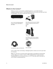
... that each item is in the carton and that each item is undamaged. Note: You will need an optional cable signal splitter and additional standard RF coaxial cables if you receive your service provider for assistance. What's In the Carton? What's In the Carton?
... that each item is in the carton and that each item is undamaged. Note: You will need an optional cable signal splitter and additional standard RF coaxial cables if you receive your service provider for assistance. What's In the Carton? What's In the Carton?
User Guide
Page 20
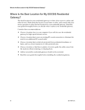
... location for My DOCSIS Residential Gateway? Read this user guide thoroughly before you will also use the residential gateway for an additional RF coaxial outlet. Choose a location so that there is plenty of your home or office, and consult with your residential gateway. Consider...recommendations: Choose a location close to eliminate the need for high-speed Internet service. Choose a location that is near an existing RF coaxial connection to your residential gateway. Choose a location that is relatively protected from the modem without straining or crimping them. Where ...
... location for My DOCSIS Residential Gateway? Read this user guide thoroughly before you will also use the residential gateway for an additional RF coaxial outlet. Choose a location so that there is plenty of your home or office, and consult with your residential gateway. Consider...recommendations: Choose a location close to eliminate the need for high-speed Internet service. Choose a location that is near an existing RF coaxial connection to your residential gateway. Choose a location that is relatively protected from the modem without straining or crimping them. Where ...
User Guide
Page 25
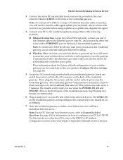
... switch(s). „ Wireless: Make sure that your PC does not have immediate Internet access. How Do I Connect My Gateway for Internet Service? 3 Connect the active RF coaxial cable from the same cable connection, you will need to associate your wireless device with your PC, and connect the other end to the...
... switch(s). „ Wireless: Make sure that your PC does not have immediate Internet access. How Do I Connect My Gateway for Internet Service? 3 Connect the active RF coaxial cable from the same cable connection, you will need to associate your wireless device with your PC, and connect the other end to the...
User Guide
Page 94
... a different cable, your residential gateway to determine whether you will illuminate continuously. Your NIC card or USB interface may be equipped with a standard 75-ohm RF coaxial cable. They offer a wide range of the front panel status indicator lights. If you subscribe to cable television service, you can watch TV and...
... a different cable, your residential gateway to determine whether you will illuminate continuously. Your NIC card or USB interface may be equipped with a standard 75-ohm RF coaxial cable. They offer a wide range of the front panel status indicator lights. If you subscribe to cable television service, you can watch TV and...
Hardware Installation Guide
Page 205
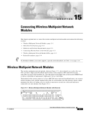
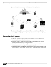
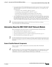
...690 GHz) or unlicensed U-NII band (5.725 to as a subscriber unit (SU), provides a high-speed broadband fixed wireless radio-frequency (RF) link between each subscriber site and a single headend site. The headend of the system consists of fading, uses two wireless transverters at each... • Related Documents, page 15-4 Tip To determine whether your router supports a specific network module, see Table 1-6 on page 1-16. The diversity option, which minimizes the effects of a Cisco uBR7200 series universal broadband router, one or more wireless modem cards, and the required subsystem for each...
...690 GHz) or unlicensed U-NII band (5.725 to as a subscriber unit (SU), provides a high-speed broadband fixed wireless radio-frequency (RF) link between each subscriber site and a single headend site. The headend of the system consists of fading, uses two wireless transverters at each... • Related Documents, page 15-4 Tip To determine whether your router supports a specific network module, see Table 1-6 on page 1-16. The diversity option, which minimizes the effects of a Cisco uBR7200 series universal broadband router, one or more wireless modem cards, and the required subsystem for each...
Hardware Installation Guide
Page 206
... of the necessary cables and these items: • A wireless multipoint network module in the router • One or two antennas to transmit and receive RF signals to the radio frequency (RF) subsystem in Figure 15-3, or mounted separately. • One power injector for each transverter.... Chapter 15 Connecting Wireless Multipoint Network Modules Figure 15-2 Multipoint Communications with DC power, control signals, and IF signals. 15-2 Cisco Network Modules Hardware Installation Guide OL-2485-20 It also provides the up-down conversion from the headend. (Diversity reception of the...
... of the necessary cables and these items: • A wireless multipoint network module in the router • One or two antennas to transmit and receive RF signals to the radio frequency (RF) subsystem in Figure 15-3, or mounted separately. • One power injector for each transverter.... Chapter 15 Connecting Wireless Multipoint Network Modules Figure 15-2 Multipoint Communications with DC power, control signals, and IF signals. 15-2 Cisco Network Modules Hardware Installation Guide OL-2485-20 It also provides the up-down conversion from the headend. (Diversity reception of the...
Hardware Installation Guide
Page 345
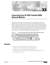
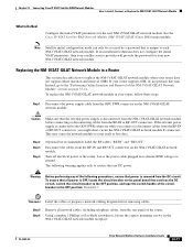
Figure 33-1 Cisco IP VSAT Satellite WAN Network Module (NM-1VSAT-GILAT) Faceplate NM-1VSAT GILAT RF-IN EXT RX ON DC LOCK SYNC LINE TX ODU PWR RF-OUT EN 127051 Contents • Prerequisites for the NM-1VSAT-GILAT Network Module, page 33-2 • Restrictions for the...page 33-3 • How to a satellite, and the satellite sends and receives signals from an earthbound central hub, which provides Cisco modular access routers with two-way satellite WAN connectivity in Gilat SkyEdge-compatible satellite communications networks. The ODU receives and sends signals to Install, Connect, ...
Figure 33-1 Cisco IP VSAT Satellite WAN Network Module (NM-1VSAT-GILAT) Faceplate NM-1VSAT GILAT RF-IN EXT RX ON DC LOCK SYNC LINE TX ODU PWR RF-OUT EN 127051 Contents • Prerequisites for the NM-1VSAT-GILAT Network Module, page 33-2 • Restrictions for the...page 33-3 • How to a satellite, and the satellite sends and receives signals from an earthbound central hub, which provides Cisco modular access routers with two-way satellite WAN connectivity in Gilat SkyEdge-compatible satellite communications networks. The ODU receives and sends signals to Install, Connect, ...
Hardware Installation Guide
Page 347
...Module Connectors, page 33-7 • Outbound and Inbound Directions in this document, you plan to the RF-IN or RF-OUT connector - Chapter 33 Connecting Cisco IP VSAT Satellite WAN Network Modules Information About the NM-1VSAT-GILAT Network Module • To avoid ...damaging the NM-1VSAT-GILAT network module, disconnect the power supply from the router chassis • After completing the hardware installation, moving the router...
...Module Connectors, page 33-7 • Outbound and Inbound Directions in this document, you plan to the RF-IN or RF-OUT connector - Chapter 33 Connecting Cisco IP VSAT Satellite WAN Network Modules Information About the NM-1VSAT-GILAT Network Module • To avoid ...damaging the NM-1VSAT-GILAT network module, disconnect the power supply from the router chassis • After completing the hardware installation, moving the router...
Hardware Installation Guide
Page 348
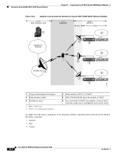
... a branch office network connected to an Ethernet port on the router At a high level, the many components of an enterprise satellite communications network can be divided into three categories: • Satellite • Hub • VSATs 33-4 Cisco Network Modules Hardware Installation Guide OL-2485-20 VSAT = very small... Network Module Land (HQ, Internet, hub) Space (satellite) ODU Land (VSATs) IDU 1 6 Intranet or Internet 4 NM-1VSAT GILAT RF-IN EXT RE ON DC LOCK SYNC LINE TX ODU PWR RF-OUT EN 5 W0 LINK ETHERNET 1 ACT LINK ETHERNET 0 ACT CONSOLE AUX 6 3 4 NM-1VSAT GILAT...
... a branch office network connected to an Ethernet port on the router At a high level, the many components of an enterprise satellite communications network can be divided into three categories: • Satellite • Hub • VSATs 33-4 Cisco Network Modules Hardware Installation Guide OL-2485-20 VSAT = very small... Network Module Land (HQ, Internet, hub) Space (satellite) ODU Land (VSATs) IDU 1 6 Intranet or Internet 4 NM-1VSAT GILAT RF-IN EXT RE ON DC LOCK SYNC LINE TX ODU PWR RF-OUT EN 5 W0 LINK ETHERNET 1 ACT LINK ETHERNET 0 ACT CONSOLE AUX 6 3 4 NM-1VSAT GILAT...
Hardware Installation Guide
Page 351
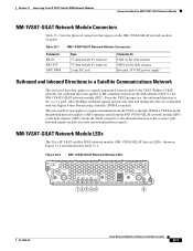
...33-4 NM-1VSAT-GILAT Network Module LEDs NM-1VSAT GILAT RF-IN EXT RX ON DC LOCK SYNC LINE TX ODU PWR RF-OUT EN 117347 12345 6 OL-2485-20 Cisco Network Modules Hardware Installation Guide 33-7 Table 33-1 Connector RF-IN RF-OUT ODU PWR NM-1VSAT-GILAT Network Module Connectors Type ...VSAT perspective, the inbound direction is the receive path. Within a VSAT network, the inbound direction applies to RF communication from the VSAT to the VSAT. NM-1VSAT-GILAT Network Module LEDs The Cisco IP VSAT satellite WAN network module (NM-1VSAT-GILAT) has six LEDs, shown in Figure 33-4 and ...
...33-4 NM-1VSAT-GILAT Network Module LEDs NM-1VSAT GILAT RF-IN EXT RX ON DC LOCK SYNC LINE TX ODU PWR RF-OUT EN 117347 12345 6 OL-2485-20 Cisco Network Modules Hardware Installation Guide 33-7 Table 33-1 Connector RF-IN RF-OUT ODU PWR NM-1VSAT-GILAT Network Module Connectors Type ...VSAT perspective, the inbound direction is the receive path. Within a VSAT network, the inbound direction applies to RF communication from the VSAT to the VSAT. NM-1VSAT-GILAT Network Module LEDs The Cisco IP VSAT satellite WAN network module (NM-1VSAT-GILAT) has six LEDs, shown in Figure 33-4 and ...
Hardware Installation Guide
Page 353
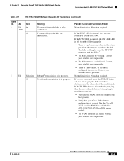
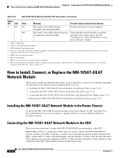
...you are concerned about the TX LED being off , then the following apply: • There is in progress. Check the cabling between the RF-OUT connector and the SSPA.7 • The SSPA may not be working. If the TX LED does not flicker during the ping, then the...to the hub. • Wait until the VSAT software completes the boot process. • Verify that your satellite service provider. Chapter 33 Connecting Cisco IP VSAT Satellite WAN Network Modules Information About the NM-1VSAT-GILAT Network Module Table 33-2 NM-1VSAT-GILAT Network Module LED Descriptions (continued) ...
...you are concerned about the TX LED being off , then the following apply: • There is in progress. Check the cabling between the RF-OUT connector and the SSPA.7 • The SSPA may not be working. If the TX LED does not flicker during the ping, then the...to the hub. • Wait until the VSAT software completes the boot process. • Verify that your satellite service provider. Chapter 33 Connecting Cisco IP VSAT Satellite WAN Network Modules Information About the NM-1VSAT-GILAT Network Module Table 33-2 NM-1VSAT-GILAT Network Module LED Descriptions (continued) ...
Hardware Installation Guide
Page 354
...aperture terminal. 3. The receive direction at the remote VSAT is called the outbound direction from the hub. RF = radio frequency. 7. SSPA = solid state block converter and power amplifier. 8. Off The router's Cisco IOS software does not Verify that the network module is called the inbound direction to the ODU. ODU...used to connect the NM-1VSAT-GILAT network module to the hub. How to the NM-1VSAT-GILAT network module in Cisco Access Routers" chapter of which tasks your satellite service provider performs for you: • Installing the NM-1VSAT-GILAT Network Module in the...
...aperture terminal. 3. The receive direction at the remote VSAT is called the outbound direction from the hub. RF = radio frequency. 7. SSPA = solid state block converter and power amplifier. 8. Off The router's Cisco IOS software does not Verify that the network module is called the inbound direction to the ODU. ODU...used to connect the NM-1VSAT-GILAT network module to the hub. How to the NM-1VSAT-GILAT network module in Cisco Access Routers" chapter of which tasks your satellite service provider performs for you: • Installing the NM-1VSAT-GILAT Network Module in the...
Hardware Installation Guide
Page 355
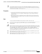
...-GILAT Network Module Note If an installation technician has already connected the NM-1VSAT-GILAT to the RF-IN or RF-OUT connectors. See the "Installing Cisco Network Modules in the router chassis. Caution Make sure that your satellite service provider for ODU and cable installation information. If...on the NM-1VSAT-GILAT network module. (See Figure 33-5.) OL-2485-20 Cisco Network Modules Hardware Installation Guide 33-11 Prerequisites • Install the NM-1VSAT-GILAT network module in Cisco Access Routers" chapter of the cable that leads to the SSPA, and connect it to...
...-GILAT Network Module Note If an installation technician has already connected the NM-1VSAT-GILAT to the RF-IN or RF-OUT connectors. See the "Installing Cisco Network Modules in the router chassis. Caution Make sure that your satellite service provider for ODU and cable installation information. If...on the NM-1VSAT-GILAT network module. (See Figure 33-5.) OL-2485-20 Cisco Network Modules Hardware Installation Guide 33-11 Prerequisites • Install the NM-1VSAT-GILAT network module in Cisco Access Routers" chapter of the cable that leads to the SSPA, and connect it to...
Hardware Installation Guide
Page 356
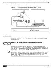
... DC LOCK SYNC LINE TX 4 ODU PWR RF-OUT EN 3 RF-IN connector 4 RF-OUT connector 127469 What to Do Next Proceed to the "Connecting the NM-1VSAT-GILAT Network Module to the software configuration tasks for your NM-1VSAT-GILAT network module. See the Cisco IP VSAT Satellite WAN Network Module (NM-1VSAT...
... DC LOCK SYNC LINE TX 4 ODU PWR RF-OUT EN 3 RF-IN connector 4 RF-OUT connector 127469 What to Do Next Proceed to the "Connecting the NM-1VSAT-GILAT Network Module to the software configuration tasks for your NM-1VSAT-GILAT network module. See the Cisco IP VSAT Satellite WAN Network Module (NM-1VSAT...
Hardware Installation Guide
Page 357
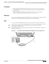
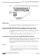
... the NM-1VSAT-GILAT network module to the Power Supply (USA) NM-1VSAT GILAT RF-IN Step 2 EXT RX ON DC LOCK SYNC LINE TX ODU PWR RF-OUT EN Step 1 127050 OL-2485-20 Cisco Network Modules Hardware Installation Guide 33-13 For Europe, see Figure 33-6. See the ..."Connecting the NM-1VSAT-GILAT Network Module to Install, Connect, or Replace the NM-1VSAT-GILAT Network Module Prerequisites • Install the NM-1VSAT-GILAT network module in the router...
... the NM-1VSAT-GILAT network module to the Power Supply (USA) NM-1VSAT GILAT RF-IN Step 2 EXT RX ON DC LOCK SYNC LINE TX ODU PWR RF-OUT EN Step 1 127050 OL-2485-20 Cisco Network Modules Hardware Installation Guide 33-13 For Europe, see Figure 33-6. See the ..."Connecting the NM-1VSAT-GILAT Network Module to Install, Connect, or Replace the NM-1VSAT-GILAT Network Module Prerequisites • Install the NM-1VSAT-GILAT network module in the router...
Hardware Installation Guide
Page 358
...Online Insertion and Removal of the NM-1VSAT-GILAT Network Module The online insertion and removal (OIR) feature enables some Cisco modular access routers to the software configuration for your router supports online insertion and removal (OIR): • Performing Online Insertion and Removal of the NM-1VSAT-GILAT Network Module,...Figure 33-7 Connecting the NM-1VSAT-GILAT Network Module to the Power Supply (Europe) NM-1VSAT GILAT RF-IN Step 2 EXT RX ON DC LOCK SYNC LINE TX ODU PWR RF-OUT EN Step 1 127468 What to Do Next Proceed to support the replacement of network modules without ...
...Online Insertion and Removal of the NM-1VSAT-GILAT Network Module The online insertion and removal (OIR) feature enables some Cisco modular access routers to the software configuration for your router supports online insertion and removal (OIR): • Performing Online Insertion and Removal of the NM-1VSAT-GILAT Network Module,...Figure 33-7 Connecting the NM-1VSAT-GILAT Network Module to the Power Supply (Europe) NM-1VSAT GILAT RF-IN Step 2 EXT RX ON DC LOCK SYNC LINE TX ODU PWR RF-OUT EN Step 1 127468 What to Do Next Proceed to support the replacement of network modules without ...
Hardware Installation Guide
Page 359
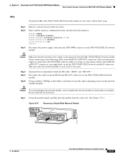
... connectors. Do not touch the circuit board. Step 7 Using the module handle, pull the network module from the RF-IN or RF-OUT connectors. Chapter 33 Connecting Cisco IP VSAT Satellite WAN Network Modules How to reset itself or lose data. Caution Make sure that the external power ...connecting or disconnecting cables from the router slot. (See Figure 33-8.) Figure 33-8 Removing a Single-Wide Network Module WO SERIAL NM-1VSAT GILAT RF-IN EXT DC RX LOCK SYNC ON LINE TX ODU PWR RF-OUT EN ACT 127418 OL-2485-20 Cisco Network Modules Hardware Installation Guide ...
... connectors. Do not touch the circuit board. Step 7 Using the module handle, pull the network module from the RF-IN or RF-OUT connectors. Chapter 33 Connecting Cisco IP VSAT Satellite WAN Network Modules How to reset itself or lose data. Caution Make sure that the external power ...connecting or disconnecting cables from the router slot. (See Figure 33-8.) Figure 33-8 Removing a Single-Wide Network Module WO SERIAL NM-1VSAT GILAT RF-IN EXT DC RX LOCK SYNC ON LINE TX ODU PWR RF-OUT EN ACT 127418 OL-2485-20 Cisco Network Modules Hardware Installation Guide ...
Hardware Installation Guide
Page 360
... PWR connector while you connect or disconnect cables from the RF-IN or RF-OUT connectors. Enter satellite interface configuration mode, and enable the satellite interface: Router> enable Router# configure terminal Router(config)# interface satellite slot/0 Router(config-if)# no shutdown Router(config-if)# end Router# 33-16 Cisco Network Modules Hardware Installation Guide OL-2485-20 Using a number...
... PWR connector while you connect or disconnect cables from the RF-IN or RF-OUT connectors. Enter satellite interface configuration mode, and enable the satellite interface: Router> enable Router# configure terminal Router(config)# interface satellite slot/0 Router(config-if)# no shutdown Router(config-if)# end Router# 33-16 Cisco Network Modules Hardware Installation Guide OL-2485-20 Using a number...
Hardware Installation Guide
Page 361
...GILAT network module F connectors. If an installation technician does not configure the initial VSAT parameters, then your router does not support online insertion and removal (OIR). If your router, follow these steps: Step 1 Disconnect the power supply cable from the rear panel of the circuit ... or lose data. To ensure that the external power supply is removed from the RF-IN or RF-OUT connectors. The following procedures, ensure that use DC power. OL-2485-20 Cisco Network Modules Hardware Installation Guide 33-17 Caution Make sure that all network cables, ...
...GILAT network module F connectors. If an installation technician does not configure the initial VSAT parameters, then your router does not support online insertion and removal (OIR). If your router, follow these steps: Step 1 Disconnect the power supply cable from the rear panel of the circuit ... or lose data. To ensure that the external power supply is removed from the RF-IN or RF-OUT connectors. The following procedures, ensure that use DC power. OL-2485-20 Cisco Network Modules Hardware Installation Guide 33-17 Caution Make sure that all network cables, ...