User Guide
Page 4
...damaged in accordance with one wider than the other apparatus (including amplifiers) that produce heat. 9) Do not defeat the safety purpose of power supply to your home or business, consult your service provider or your outlet, consult an electrician for replacement of the obsolete outlet. 10) Protect ...the power cord from tip-over. 13) Unplug this apparatus near any heat sources such as a power-supply cord or plug is damaged, liquid has been spilled or objects have fallen into your local...
...damaged in accordance with one wider than the other apparatus (including amplifiers) that produce heat. 9) Do not defeat the safety purpose of power supply to your home or business, consult your service provider or your outlet, consult an electrician for replacement of the obsolete outlet. 10) Protect ...the power cord from tip-over. 13) Unplug this apparatus near any heat sources such as a power-supply cord or plug is damaged, liquid has been spilled or objects have fallen into your local...
User Guide
Page 14
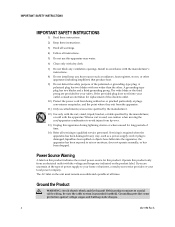
The carton contains the following items: One of the DOCSIS Residential Gateway models (DPC3825 or EPC3825) One wall-mount style power adapter (models requiring external power supply) OR One desktop-style power adapter (models requiring external power supply) One Ethernet cable (CAT5/RJ-45) One CD-ROM If any of these items are missing or damaged, please...
The carton contains the following items: One of the DOCSIS Residential Gateway models (DPC3825 or EPC3825) One wall-mount style power adapter (models requiring external power supply) OR One desktop-style power adapter (models requiring external power supply) One Ethernet cable (CAT5/RJ-45) One CD-ROM If any of these items are missing or damaged, please...
User Guide
Page 16
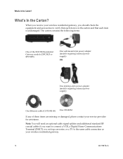
... Rev A Only use the power supply that is provided with your residential gateway. 2 ON/OFF SWITCH (European models only)-Allows you to power of the residential gateway without removing the power cord 3 MAC ADDRESS LABEL-Displays the MAC address of the back panel components on the Cisco DPC3825 residential gateway. 1 POWER-Connects the residential gateway to...
... Rev A Only use the power supply that is provided with your residential gateway. 2 ON/OFF SWITCH (European models only)-Allows you to power of the residential gateway without removing the power cord 3 MAC ADDRESS LABEL-Displays the MAC address of the back panel components on the Cisco DPC3825 residential gateway. 1 POWER-Connects the residential gateway to...
Hardware Installation Guide
Page 50
...Cisco network modules, are improperly handled and can damage equipment and impair electrical circuitry. do not become a victim yourself. - Electrostatic discharge occurs when electronic printed circuit cards, such as follows: - Installing or removing a router chassis - Always observe the following : - Working near power supplies... • Do not work area, such as damp floors, ungrounded power extension cables, or missing safety grounds. • ...
...Cisco network modules, are improperly handled and can damage equipment and impair electrical circuitry. do not become a victim yourself. - Electrostatic discharge occurs when electronic printed circuit cards, such as follows: - Installing or removing a router chassis - Always observe the following : - Working near power supplies... • Do not work area, such as damp floors, ungrounded power extension cables, or missing safety grounds. • ...

Hardware Installation Guide
Page 51
... the metal object to lift the chassis with the handles on the power supplies or on the interface processors, or by Cisco Systems, Inc. disconnect the power at the circuit breaker on AC units; To prevent injury, keep ...power supply when the power cord is connected. Statement 1030 Warning Ultimate disposal of the chassis. Statement 43 OL-2485-20 Cisco Network Modules Hardware Installation Guide 2-3 Warning Before working on a chassis or working on the front of this equipment. Chapter 2 Installing Cisco Network Modules in Cisco Access Routers Recommended Practices for Cisco...
... the metal object to lift the chassis with the handles on the power supplies or on the interface processors, or by Cisco Systems, Inc. disconnect the power at the circuit breaker on AC units; To prevent injury, keep ...power supply when the power cord is connected. Statement 1030 Warning Ultimate disposal of the chassis. Statement 43 OL-2485-20 Cisco Network Modules Hardware Installation Guide 2-3 Warning Before working on a chassis or working on the front of this equipment. Chapter 2 Installing Cisco Network Modules in Cisco Access Routers Recommended Practices for Cisco...

Hardware Installation Guide
Page 64
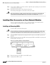
...power supply, remove the tape from the rear panel of the circuit breaker to the router. To install a double-wide or extended double-wide network module, perform these steps: Step 1 Step 2 Step 3 Turn off electrical power to the ON position. Tip See the "Where to the network and power up the router...Cisco Network Modules Hardware Installation Guide OL-2485-20 Installing Cisco Network Modules in Cisco Access Routers Chapter 2 Installing Cisco Network Modules in Cisco Access Routers Figure 2-10 Installing Single-Wide and Extended Single-Wide Network Modules in Cisco Access Routers ...
...power supply, remove the tape from the rear panel of the circuit breaker to the router. To install a double-wide or extended double-wide network module, perform these steps: Step 1 Step 2 Step 3 Turn off electrical power to the ON position. Tip See the "Where to the network and power up the router...Cisco Network Modules Hardware Installation Guide OL-2485-20 Installing Cisco Network Modules in Cisco Access Routers Chapter 2 Installing Cisco Network Modules in Cisco Access Routers Figure 2-10 Installing Single-Wide and Extended Single-Wide Network Modules in Cisco Access Routers ...
Hardware Installation Guide
Page 72
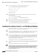
... module console session by pressing Ctrl-Shift-6, followed by x. The following warning applies to routers that use a DC power supply: Warning Before performing any of the following procedures, ensure that power is OFF, locate the circuit breaker on page 1-8 for the network module with the ... interface card in 1- Statement 7 2-24 Cisco Network Modules Hardware Installation Guide OL-2485-20 Installing Cisco Interface Cards in a 1- Open SE-netmodule con now available Press RETURN to the OFF position, and tape the switch handle of voice and data interface cards. (See Table ...
... module console session by pressing Ctrl-Shift-6, followed by x. The following warning applies to routers that use a DC power supply: Warning Before performing any of the following procedures, ensure that power is OFF, locate the circuit breaker on page 1-8 for the network module with the ... interface card in 1- Statement 7 2-24 Cisco Network Modules Hardware Installation Guide OL-2485-20 Installing Cisco Interface Cards in a 1- Open SE-netmodule con now available Press RETURN to the OFF position, and tape the switch handle of voice and data interface cards. (See Table ...
Hardware Installation Guide
Page 74
...Cisco Access Routers Step 5 Step 6 Using a number 1 Phillips or flat-blade screwdriver, tighten the captive mounting screws into a Network Module NM-1GE GBIC EN RX TX LINK 72705 Step 3 Release the side clips on the GBIC to prevent laser emissions. Step 4 Confirm that use a DC power supply: Warning After wiring the DC power supply... form-factor pluggable modules (SFPs). Hold down the clips on the side of the port when no fiber cable is seated. 2-26 Cisco Network Modules Hardware Installation Guide OL-2485-20 Reinstall the network interface cables and power up the router.
...Cisco Access Routers Step 5 Step 6 Using a number 1 Phillips or flat-blade screwdriver, tighten the captive mounting screws into a Network Module NM-1GE GBIC EN RX TX LINK 72705 Step 3 Release the side clips on the GBIC to prevent laser emissions. Step 4 Confirm that use a DC power supply: Warning After wiring the DC power supply... form-factor pluggable modules (SFPs). Hold down the clips on the side of the port when no fiber cable is seated. 2-26 Cisco Network Modules Hardware Installation Guide OL-2485-20 Reinstall the network interface cables and power up the router.
Hardware Installation Guide
Page 99
...following procedures, ensure that use a DC power supply: Warning Before performing any of the chassis. To ensure that all network interface cables, including telephone cables, from the DC circuit. Using needlenose pliers, set to the router. Remove all power is removed from the rear panel. ...J7 J6 J5 J4 75TERMI12N0ATION Top card Bottom card Place jumper in this position last Place jumper in the OFF position. OL-2485-20 Cisco Network Modules Hardware Installation Guide 4-9 Statement 7 Step 2 Step 3 Step 4 Step 5 Loosen the module captive mounting screws, using a...
...following procedures, ensure that use a DC power supply: Warning Before performing any of the chassis. To ensure that all network interface cables, including telephone cables, from the DC circuit. Using needlenose pliers, set to the router. Remove all power is removed from the rear panel. ...J7 J6 J5 J4 75TERMI12N0ATION Top card Bottom card Place jumper in this position last Place jumper in the OFF position. OL-2485-20 Cisco Network Modules Hardware Installation Guide 4-9 Statement 7 Step 2 Step 3 Step 4 Step 5 Loosen the module captive mounting screws, using a...
Hardware Installation Guide
Page 100
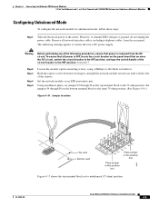
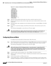
...the power cable. The following procedures, ensure that use a DC power supply: Warning Before performing any of the circuit breaker in the chassis, using a Phillips or flat-blade screwdriver. The following warning applies to the same 120-ohm position. (See Figure 4-16.) 4-10 Cisco Network...the network interface cables and turn on the bottom terminal block to routers that use a DC power supply: Warning After wiring the DC power supply, remove the tape from the circuit breaker switch handle and reinstate power by moving the handle of the chassis. Statement 8 Configuring Balanced ...
...the power cable. The following procedures, ensure that use a DC power supply: Warning Before performing any of the circuit breaker in the chassis, using a Phillips or flat-blade screwdriver. The following warning applies to the same 120-ohm position. (See Figure 4-16.) 4-10 Cisco Network...the network interface cables and turn on the bottom terminal block to routers that use a DC power supply: Warning After wiring the DC power supply, remove the tape from the circuit breaker switch handle and reinstate power by moving the handle of the chassis. Statement 8 Configuring Balanced ...
Hardware Installation Guide
Page 101
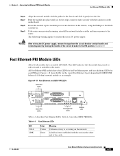
...Cisco Network Modules Hardware Installation Guide 4-11 Figure 4-18 shows LEDs for each PRI port. Table 4-1 Fast Ethernet LEDs LED COLL LINK Color Yellow Green Meaning Collision activity is available to the router. This LED indicates that use a DC power supply: Warning After wiring the DC power supply..., remove the tape from the circuit breaker switch handle and reinstate power by moving the handle of the cable. The ...
...Cisco Network Modules Hardware Installation Guide 4-11 Figure 4-18 shows LEDs for each PRI port. Table 4-1 Fast Ethernet LEDs LED COLL LINK Color Yellow Green Meaning Collision activity is available to the router. This LED indicates that use a DC power supply: Warning After wiring the DC power supply..., remove the tape from the circuit breaker switch handle and reinstate power by moving the handle of the cable. The ...
Hardware Installation Guide
Page 163
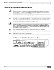
...the captive screws between two fingers, and pull the network module toward you must turn off electrical power to the router. The following warning applies to routers that use a DC power supply: Warning Before performing any of the following procedures, ensure that services the DC circuit, switch the... 100-240VAC 50/60HZ 3.0-1.5 AMPS REMOTE ALARM LOCAL ALARM LOOPBACK CARRIER DETECT ACT LNK ACT ACT LNK ACT H11202 OL-2485-20 Cisco Network Modules Hardware Installation Guide 9-5 Chapter 9 Connecting Digital Modem Network Modules Adding 6-Port MICA Modules to a Digital Modem Network Module...
...the captive screws between two fingers, and pull the network module toward you must turn off electrical power to the router. The following warning applies to routers that use a DC power supply: Warning Before performing any of the following procedures, ensure that services the DC circuit, switch the... 100-240VAC 50/60HZ 3.0-1.5 AMPS REMOTE ALARM LOCAL ALARM LOOPBACK CARRIER DETECT ACT LNK ACT ACT LNK ACT H11202 OL-2485-20 Cisco Network Modules Hardware Installation Guide 9-5 Chapter 9 Connecting Digital Modem Network Modules Adding 6-Port MICA Modules to a Digital Modem Network Module...
Hardware Installation Guide
Page 169
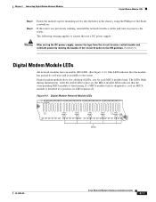
... ON position. The following warning applies to routers that use a DC power supply: Warning After wiring the DC power supply, remove the tape from the circuit breaker switch handle and reinstate power by moving the handle of the circuit breaker to the router. Chapter 9 Connecting Digital Modem Network Modules... BANK 0 MICA BANK 1 MICA BANK 2 MICA BANK 3 MICA BANK 4 EN H10824 LEDs OL-2485-20 Cisco Network Modules Hardware Installation Guide 9-11 If the router was previously running, reinstall the network interface cables and turn on , the MICA module LEDs indicate that the module...
... ON position. The following warning applies to routers that use a DC power supply: Warning After wiring the DC power supply, remove the tape from the circuit breaker switch handle and reinstate power by moving the handle of the circuit breaker to the router. Chapter 9 Connecting Digital Modem Network Modules... BANK 0 MICA BANK 1 MICA BANK 2 MICA BANK 3 MICA BANK 4 EN H10824 LEDs OL-2485-20 Cisco Network Modules Hardware Installation Guide 9-11 If the router was previously running, reinstall the network interface cables and turn on , the MICA module LEDs indicate that the module...
Hardware Installation Guide
Page 217
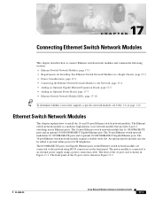
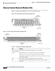
...Tip To determine whether your router supports a specific network module, see Table 1-6 on page 1-16. The front of the 36-port card is a modular, high-density voice network module that provides Layer... modules. The Ethernet switch network module is shown in Figure 17-1. OL-2485-20 Cisco Network Modules Hardware Installation Guide 17-1 The 36-port Ethernet switch network module has 36...chapter explains how to the network using a power connection cable. The front panel of the 16-port card is connected to an external power supply using RJ-45 connectors on the Ethernet ...
...Tip To determine whether your router supports a specific network module, see Table 1-6 on page 1-16. The front of the 36-port card is a modular, high-density voice network module that provides Layer... modules. The Ethernet switch network module is shown in Figure 17-1. OL-2485-20 Cisco Network Modules Hardware Installation Guide 17-1 The 36-port Ethernet switch network module has 36...chapter explains how to the network using a power connection cable. The front panel of the 16-port card is connected to an external power supply using RJ-45 connectors on the Ethernet ...
Hardware Installation Guide
Page 218
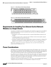
.... For information about intrachassis stacking configuration, see the 16- Power Considerations The Ethernet switch network module supports inline powering of IP telephones with AC-IP power supplies) to the Ethernet switch service modules. Cisco 2800 series, Cisco 3700 series, and Cisco 3800 series routers supply -48 V power internally (with -48-V power. Each port can be installed in the VLAN databases, and...
.... For information about intrachassis stacking configuration, see the 16- Power Considerations The Ethernet switch network module supports inline powering of IP telephones with AC-IP power supplies) to the Ethernet switch service modules. Cisco 2800 series, Cisco 3700 series, and Cisco 3800 series routers supply -48 V power internally (with -48-V power. Each port can be installed in the VLAN databases, and...
Hardware Installation Guide
Page 219
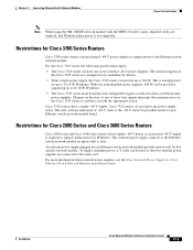
... two nonredundant power supplies, 640 W can take the appropriate action. Cisco 3725 routers do not supply -48-V power, so an external -48-V supply is enough power for Cisco 3700 Series Routers Cisco 3700 series routers contain internal -48-V power supplies to supply power to 360 W. For more information about external power supplies, see the Cisco External Power Supply for Cisco 2600 Series and Cisco 3600 Series Routers Cisco 2600 series and Cisco 3600 series routers do not...
... two nonredundant power supplies, 640 W can take the appropriate action. Cisco 3725 routers do not supply -48-V power, so an external -48-V supply is enough power for Cisco 3700 Series Routers Cisco 3700 series routers contain internal -48-V power supplies to supply power to 360 W. For more information about external power supplies, see the Cisco External Power Supply for Cisco 2600 Series and Cisco 3600 Series Routers Cisco 2600 series and Cisco 3600 series routers do not...
Hardware Installation Guide
Page 221
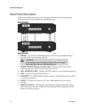
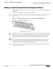
...network modules.) Caution Be sure to press firmly on the Gigabit Ethernet board port, as shown in Figure 17-4. ESW16 15x External power supply port cover FastEthernet Ports 8x 7x 15x 7x 14x 6x 13x 5x 12x 4x 11x 3x 10x 2x 9x 1x 0x 8x 0x ... cover Guide the external connector through the Gigabit Ethernet expansion board into the board connector on the Ethernet Switch Network Module NM- OL-2485-20 Cisco Network Modules Hardware Installation Guide 17-5 To install a Gigabit Ethernet expansion board, follow these steps: Step 1 Use a Phillips screwdriver to support ...
...network modules.) Caution Be sure to press firmly on the Gigabit Ethernet board port, as shown in Figure 17-4. ESW16 15x External power supply port cover FastEthernet Ports 8x 7x 15x 7x 14x 6x 13x 5x 12x 4x 11x 3x 10x 2x 9x 1x 0x 8x 0x ... cover Guide the external connector through the Gigabit Ethernet expansion board into the board connector on the Ethernet Switch Network Module NM- OL-2485-20 Cisco Network Modules Hardware Installation Guide 17-5 To install a Gigabit Ethernet expansion board, follow these steps: Step 1 Use a Phillips screwdriver to support ...
Hardware Installation Guide
Page 223
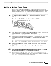
... and Figure 17-9 for IP telephones. See the Cisco External Power Supply for Cisco Ethernet Switch Network Modules Installation Guide for Cisco Ethernet Switch Network Modules Installation Guide. Installation and configuration of the external power supply system is installed. Figure 17-7 Power Board Port Cover on the front of the network...into the connector on the front of the network module. Step 7 After installing the network module into the router chassis. ESW16 15x External power supply port cover FastEthernet Ports 8x 7x 15x 7x 14x 6x 13x 5x 12x 4x 11x 3x 10x 2x 9x ...
... and Figure 17-9 for IP telephones. See the Cisco External Power Supply for Cisco Ethernet Switch Network Modules Installation Guide for Cisco Ethernet Switch Network Modules Installation Guide. Installation and configuration of the external power supply system is installed. Figure 17-7 Power Board Port Cover on the front of the network...into the connector on the front of the network module. Step 7 After installing the network module into the router chassis. ESW16 15x External power supply port cover FastEthernet Ports 8x 7x 15x 7x 14x 6x 13x 5x 12x 4x 11x 3x 10x 2x 9x ...
Hardware Installation Guide
Page 226
... Gigabit Ethernet port is a problem with one or more of the internal or external -48-V power supplies. GE Green indicates that there is functioning. EN Green indicates that no -48-V power is available to the network module. Figure 17-10 16-Port Ethernet Switch Network Module LEDs Gigabit... -48-V Off indicates that the module has passed its self-tests and is going to the router. 17-10 Cisco Network Modules Hardware Installation Guide OL-2485-20 Green indicates -48-V power is present on the network module. Figure 17-11 shows 36-port Ethernet switch network module LEDs....
... Gigabit Ethernet port is a problem with one or more of the internal or external -48-V power supplies. GE Green indicates that there is functioning. EN Green indicates that no -48-V power is available to the network module. Figure 17-10 16-Port Ethernet Switch Network Module LEDs Gigabit... -48-V Off indicates that the module has passed its self-tests and is going to the router. 17-10 Cisco Network Modules Hardware Installation Guide OL-2485-20 Green indicates -48-V power is present on the network module. Figure 17-11 shows 36-port Ethernet switch network module LEDs....
Hardware Installation Guide
Page 239
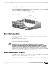
... PWR EN 122217 Power Considerations This section describes the power considerations for the router, the service module, and stacking the service modules: • Power Considerations for the Router • Power Considerations for the Service Module • Powering Considerations for the Router Cisco 2800 series, Cisco 3700 series, and Cisco 3800 series routers supply -48 V power internally (with AC-IP power supplies) to the Cisco EtherSwitch service modules...
... PWR EN 122217 Power Considerations This section describes the power considerations for the router, the service module, and stacking the service modules: • Power Considerations for the Router • Power Considerations for the Service Module • Powering Considerations for the Router Cisco 2800 series, Cisco 3700 series, and Cisco 3800 series routers supply -48 V power internally (with AC-IP power supplies) to the Cisco EtherSwitch service modules...


