User Guide
Page 12
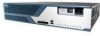
... the home network from unauthorized access Attractive compact design that meets industry standards for vertical, horizontal, or wall-mounted operation 12 4021196 Rev A Your new Cisco® Model DPC3825 DOCSIS® 3.0 or EPC3825 EuroDOCSIS™ Wireless Residential Gateway is a cable modem that allows for high-speed data connectivity.
... the home network from unauthorized access Attractive compact design that meets industry standards for vertical, horizontal, or wall-mounted operation 12 4021196 Rev A Your new Cisco® Model DPC3825 DOCSIS® 3.0 or EPC3825 EuroDOCSIS™ Wireless Residential Gateway is a cable modem that allows for high-speed data connectivity.

User Guide
Page 17
Back Panel Description 8 RESET-A momentary pressing (1-2 seconds) of all settings and then reboots the gateway CAUTION: The Reset button is for more than ten seconds first causes a reset-to-factorydefault of this switch reboots the EMTA. Doing so may cause you have selected. 4021196 Rev A 17 Do not use unless instructed to lose any cable modem settings you to do so by your cable service provider. Pressing the switch for maintenance purposes only.
Back Panel Description 8 RESET-A momentary pressing (1-2 seconds) of all settings and then reboots the gateway CAUTION: The Reset button is for more than ten seconds first causes a reset-to-factorydefault of this switch reboots the EMTA. Doing so may cause you have selected. 4021196 Rev A 17 Do not use unless instructed to lose any cable modem settings you to do so by your cable service provider. Pressing the switch for maintenance purposes only.
User Guide
Page 20
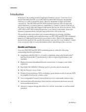
Choose a location that there is relatively protected from the modem without straining or crimping them. Read this user guide thoroughly before installing the residential gateway. 20 4021196 Rev A Consider these recommendations: Choose a location close to ... home or office, and consult with your service provider to place your residential gateway. Choose a location that is where it has access to guide the cables away from accidental disturbance or harm, such as a closet, basement, or other devices. Think about the layout of room to outlets and other protected area...
Choose a location that there is relatively protected from the modem without straining or crimping them. Read this user guide thoroughly before installing the residential gateway. 20 4021196 Rev A Consider these recommendations: Choose a location close to ... home or office, and consult with your service provider to place your residential gateway. Choose a location that is where it has access to guide the cables away from accidental disturbance or harm, such as a closet, basement, or other devices. Think about the layout of room to outlets and other protected area...
User Guide
Page 21
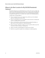
...mounting illustrations shown on all cables so that you begin, choose an appropriate mounting place. The mounting location should be able to cabling. The modem can be mounted vertically or horizontally. How Do I Mount the Modem on a Wall? (Optional) How Do I Mount the Modem on a Wall? (Optional)... You can be free of obstructions on the following pages Mount the modem as appropriate for any flooring...
...mounting illustrations shown on all cables so that you begin, choose an appropriate mounting place. The mounting location should be able to cabling. The modem can be mounted vertically or horizontally. How Do I Mount the Modem on a Wall? (Optional) How Do I Mount the Modem on a Wall? (Optional)... You can be free of obstructions on the following pages Mount the modem as appropriate for any flooring...
User Guide
Page 23
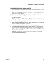
How Do I Mount the Modem on a Wall? (Optional) Mounting the Residential Gateway on the back of the keyhole slot contacts the screw shaft. Note: The preceding graphic illustrates the location ... before you mounting the residential gateway into a drywall or concrete surface where a wooden stud is available? „ If yes, go to step 3. „ If no cables or wires are connected to step 4. 3 Install the mounting screws into the wall; Important: Verify that no , drive the anchor bolts into the wall, and...
How Do I Mount the Modem on a Wall? (Optional) Mounting the Residential Gateway on the back of the keyhole slot contacts the screw shaft. Note: The preceding graphic illustrates the location ... before you mounting the residential gateway into a drywall or concrete surface where a wooden stud is available? „ If yes, go to step 3. „ If no cables or wires are connected to step 4. 3 Install the mounting screws into the wall; Important: Verify that no , drive the anchor bolts into the wall, and...
User Guide
Page 25
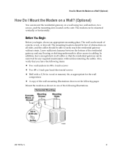
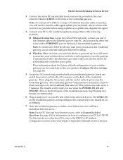
Always check with your residential gateway. The modem will be ready for use an external multi-port Ethernet switch(s). „ Wireless: Make sure that your wireless device is powered up. Insert one end of the Ethernet cable to the Ethernet port on your PC, and connect the other ... directions provided with your PC to the residential gateway using either of the following methods. „ Ethernet Connection: Locate the yellow Ethernet cable, connect one end of the User Guide or Operations Manual for associating with the wireless gateway once the gateway is online, most Internet ...
Always check with your residential gateway. The modem will be ready for use an external multi-port Ethernet switch(s). „ Wireless: Make sure that your wireless device is powered up. Insert one end of the Ethernet cable to the Ethernet port on your PC, and connect the other ... directions provided with your PC to the residential gateway using either of the following methods. „ Ethernet Connection: Locate the yellow Ethernet cable, connect one end of the User Guide or Operations Manual for associating with the wireless gateway once the gateway is online, most Internet ...
User Guide
Page 84
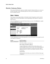
...settings. Current Time The time, based on the time zone selected on the Basic Setup page is used to connect to the cable modem termination system (CMTS) at the headend. Monitor Gateway Status Monitor Gateway Status This section describes the options available under the Status... tab that uniquely identifies each node of a network. MAC Address (CM MAC Address) A unique alphanumeric address for the cable modem coaxial interface, which is displayed. 84 4021196 Rev A Use the descriptions in the following table to perform diagnostics on -screen. A media access...
...settings. Current Time The time, based on the time zone selected on the Basic Setup page is used to connect to the cable modem termination system (CMTS) at the headend. Monitor Gateway Status Monitor Gateway Status This section describes the options available under the Status... tab that uniquely identifies each node of a network. MAC Address (CM MAC Address) A unique alphanumeric address for the cable modem coaxial interface, which is displayed. 84 4021196 Rev A Use the descriptions in the following table to perform diagnostics on -screen. A media access...
User Guide
Page 89
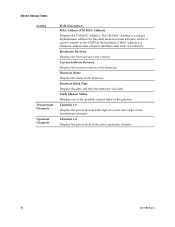
... Displays the manufacturer of the residential gateway Hardware Revision Displays the revision of the circuit board design Serial Number Displays the unique serial of your cable modem.
... Displays the manufacturer of the residential gateway Hardware Revision Displays the revision of the circuit board design Serial Number Displays the unique serial of your cable modem.
User Guide
Page 90
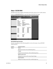
...version of the firmware Firmware Name Displays the name of the firmware Firmware Build Time Displays the date and time the firmware was built Cable Modem Status Displays one of the possible current states of the gateway Channels 1-8 Displays the power level and the signal to the CMTS ...at the headend. The CM MAC Address is a unique alphanumeric address for the cable modem coaxial interface, which is a hardware address that uniquely identifies each node of the active upstream channels 90 4021196 Rev A A MAC address is used...
...version of the firmware Firmware Name Displays the name of the firmware Firmware Build Time Displays the date and time the firmware was built Cable Modem Status Displays one of the possible current states of the gateway Channels 1-8 Displays the power level and the signal to the CMTS ...at the headend. The CM MAC Address is a unique alphanumeric address for the cable modem coaxial interface, which is a hardware address that uniquely identifies each node of the active upstream channels 90 4021196 Rev A A MAC address is used...
User Guide
Page 93
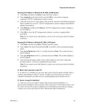
.... 4 Type ipconfig/renew at the C:/ prompt and press Enter. The IP Configuration window displays a new IP address. 5 Click OK to cable TV service. A professional installation ensures proper cable connection to the modem and to close the IP Configuration window, you have completed this procedure. Frequently Asked Questions Renewing the IP Address on Windows...
.... 4 Type ipconfig/renew at the C:/ prompt and press Enter. The IP Configuration window displays a new IP address. 5 Click OK to cable TV service. A professional installation ensures proper cable connection to the modem and to close the IP Configuration window, you have completed this procedure. Frequently Asked Questions Renewing the IP Address on Windows...
User Guide
Page 94
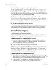
..., follow the installation instructions very carefully. Your NIC card or USB interface may be equipped with a standard 75-ohm RF coaxial cable. A. The residential gateway does not register an Ethernet connection Verify that your computer has an Ethernet card and that the Ethernet driver...(on page 96), for more detailed information on your residential gateway will need. The residential gateway does not register a cable connection The modem works with a Gigabit Ethernet card. For best performance over an Ethernet connection, your residential gateway to the PC using a different...
..., follow the installation instructions very carefully. Your NIC card or USB interface may be equipped with a standard 75-ohm RF coaxial cable. A. The residential gateway does not register an Ethernet connection Verify that your computer has an Ethernet card and that the Ethernet driver...(on page 96), for more detailed information on your residential gateway will need. The residential gateway does not register a cable connection The modem works with a Gigabit Ethernet card. For best performance over an Ethernet connection, your residential gateway to the PC using a different...
User Guide
Page 99
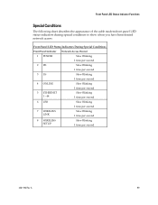
Front Panel LED Status Indicator Functions Special Conditions The following chart describes the appearance of the cable modem front panel LED status indicators during special conditions to show when you have been denied network access. Front Panel LED Status Indicators During Special Conditions ...
Front Panel LED Status Indicator Functions Special Conditions The following chart describes the appearance of the cable modem front panel LED status indicators during special conditions to show when you have been denied network access. Front Panel LED Status Indicators During Special Conditions ...
Hardware Installation Guide
Page 27
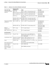
Chapter 1 Overview of Cisco Network Modules for Cisco Access Routers Cabling for Cisco Network Modules Table 1-3 Cabling for Cisco Network Modules (continued) Connection Type Connector Type, Cable Color Cable Use with Channelized E1 PRI, balanced DB-15, tan DB-15 to DB-15 120-ohm balanced E1 DB-15 to... NM-16A/S part numbers Serial surge protection Cisco Product ID CAB-SS-SURGE Fractional DS3 or below, to DSU 50-pin D, blue DB-50 HSSI DTE NM-1HSSI Fractional DS3 or below, to another router DB-50 HSSI null modem OL-2485-20 Cisco Network Modules Hardware Installation Guide 1-13
Chapter 1 Overview of Cisco Network Modules for Cisco Access Routers Cabling for Cisco Network Modules Table 1-3 Cabling for Cisco Network Modules (continued) Connection Type Connector Type, Cable Color Cable Use with Channelized E1 PRI, balanced DB-15, tan DB-15 to DB-15 120-ohm balanced E1 DB-15 to... NM-16A/S part numbers Serial surge protection Cisco Product ID CAB-SS-SURGE Fractional DS3 or below, to DSU 50-pin D, blue DB-50 HSSI DTE NM-1HSSI Fractional DS3 or below, to another router DB-50 HSSI null modem OL-2485-20 Cisco Network Modules Hardware Installation Guide 1-13
Hardware Installation Guide
Page 104
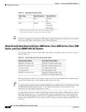
... serial cable X.21 serial cable EIA/TIA-530 serial cable Cisco Smart Serial Cables EIA/TIA-232 Smart Serial cable EIA/TIA-449 Smart Serial cable V.35 Smart Serial cable X.21 Smart Serial cable EIA/TIA-530 Smart Serial cable EIA/TIA-530A Smart Serial cable The documentation for use with Cisco 2600 Series, Cisco 3600 Series, Cisco 3700 Series, and Cisco MWR 1941-DC Routers Cisco...
... serial cable X.21 serial cable EIA/TIA-530 serial cable Cisco Smart Serial Cables EIA/TIA-232 Smart Serial cable EIA/TIA-449 Smart Serial cable V.35 Smart Serial cable X.21 Smart Serial cable EIA/TIA-530 Smart Serial cable EIA/TIA-530A Smart Serial cable The documentation for use with Cisco 2600 Series, Cisco 3600 Series, Cisco 3700 Series, and Cisco MWR 1941-DC Routers Cisco...
Hardware Installation Guide
Page 106
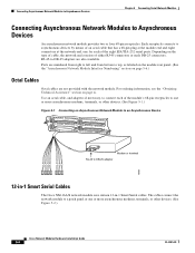
... 5 1 4 0 7 3 6 2 5 1 4 0 ASYNC 16-23 ASYNC 0-7 EN Modem or terminal RJ-45 to a patch panel or one for each of the eight EIA/TIA-232 serial ports. The cables connect the network module to DB-25 adapter H9999 12-in-1 Smart Serial Cables The Cisco NM-16A/S network module uses sixteen 12-in... Modules to asynchronous devices by means of an octal cable that has a 68-pin plug at the module end and eight connectors at the network end, one or more asynchronous modems, terminals, or other devices. (See Figure 5-2.) Cisco Network Modules Hardware Installation Guide 5-4 OL-2485-20
... 5 1 4 0 7 3 6 2 5 1 4 0 ASYNC 16-23 ASYNC 0-7 EN Modem or terminal RJ-45 to a patch panel or one for each of the eight EIA/TIA-232 serial ports. The cables connect the network module to DB-25 adapter H9999 12-in-1 Smart Serial Cables The Cisco NM-16A/S network module uses sixteen 12-in... Modules to asynchronous devices by means of an octal cable that has a 68-pin plug at the module end and eight connectors at the network end, one or more asynchronous modems, terminals, or other devices. (See Figure 5-2.) Cisco Network Modules Hardware Installation Guide 5-4 OL-2485-20
Hardware Installation Guide
Page 111
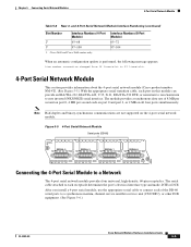
...4-Port Serial Network Module This section provides information about the 4-port serial network module (Cisco product number NM-4T). (See Figure 5-5.) With the appropriate serial transition cable, each receptacle determines the port's electrical interface type and mode, DTE or DCE. The...to a synchronous modem, channel service unit/data service unit (CSU/DSU), or other DCE equipment. (See Figure 5-6.) OL-2485-20 Cisco Network Modules Hardware Installation Guide 5-9 Cisco 3640 and Cisco 3660 routers only. After you install a 4-port serial module, use the appropriate serial cable to a ...
...4-Port Serial Network Module This section provides information about the 4-port serial network module (Cisco product number NM-4T). (See Figure 5-5.) With the appropriate serial transition cable, each receptacle determines the port's electrical interface type and mode, DTE or DCE. The...to a synchronous modem, channel service unit/data service unit (CSU/DSU), or other DCE equipment. (See Figure 5-6.) OL-2485-20 Cisco Network Modules Hardware Installation Guide 5-9 Cisco 3640 and Cisco 3660 routers only. After you install a 4-port serial module, use the appropriate serial cable to a ...
Hardware Installation Guide
Page 163
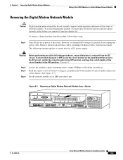
...DC circuit. Chapter 9 Connecting Digital Modem Network Modules Adding 6-Port MICA Modules to a Digital Modem Network Module Removing the Digital Modem Network Module Caution Digital modem network modules do not unplug the power cable. Remove all power is removed from a Router cT1 PRI 3 ETHERNET 4E 1 ...MODEMS EN ETH 0 MICA 2E 2W W1 BANK 0 MICA BANK 1 STP EN ETHERNET 1 MICA BANK 2 MICA BANK 3 MICA BANK 4 EN ETHERNET 0 2 SERIAL AUI EN INPUT 100-240VAC 50/60HZ 3.0-1.5 AMPS REMOTE ALARM LOCAL ALARM LOOPBACK CARRIER DETECT ACT LNK ACT ACT LNK ACT H11202 OL-2485-20 Cisco...
...DC circuit. Chapter 9 Connecting Digital Modem Network Modules Adding 6-Port MICA Modules to a Digital Modem Network Module Removing the Digital Modem Network Module Caution Digital modem network modules do not unplug the power cable. Remove all power is removed from a Router cT1 PRI 3 ETHERNET 4E 1 ...MODEMS EN ETH 0 MICA 2E 2W W1 BANK 0 MICA BANK 1 STP EN ETHERNET 1 MICA BANK 2 MICA BANK 3 MICA BANK 4 EN ETHERNET 0 2 SERIAL AUI EN INPUT 100-240VAC 50/60HZ 3.0-1.5 AMPS REMOTE ALARM LOCAL ALARM LOOPBACK CARRIER DETECT ACT LNK ACT ACT LNK ACT H11202 OL-2485-20 Cisco...
Hardware Installation Guide
Page 169
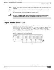
... to the router. Chapter 9 Connecting Digital Modem Network Modules Digital Modem Module LEDs Step 3 Step 4 Fasten the module captive mounting screws into the holes in a position, its self-tests and is functioning. If the router was previously running, reinstall the network interface cables and turn... LEDs, one for each MICA module bank. Figure 9-9 Digital Modem Network Module LEDs DIGITAL MODEMS MICA BANK 0 MICA BANK 1 MICA BANK 2 MICA BANK 3 MICA BANK 4 EN H10824 LEDs OL-2485-20 Cisco Network Modules Hardware Installation Guide 9-11 The LEDs blink during initialization...
... to the router. Chapter 9 Connecting Digital Modem Network Modules Digital Modem Module LEDs Step 3 Step 4 Fasten the module captive mounting screws into the holes in a position, its self-tests and is functioning. If the router was previously running, reinstall the network interface cables and turn... LEDs, one for each MICA module bank. Figure 9-9 Digital Modem Network Module LEDs DIGITAL MODEMS MICA BANK 0 MICA BANK 1 MICA BANK 2 MICA BANK 3 MICA BANK 4 EN H10824 LEDs OL-2485-20 Cisco Network Modules Hardware Installation Guide 9-11 The LEDs blink during initialization...
Hardware Installation Guide
Page 172
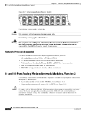
... to 4 error correction • MNP 10 for high performance under all line conditions • MNP 10EC for Modems (LAPM), and MNP 2 to intra-building or non-exposed wiring or cabling. The following protocols: • All standard data rates from 300 bps to 33.6 kbps (V.34bis) •... Telecom will be grounded at both ends. 10-2 Cisco Network Modules Hardware Installation Guide OL-2485-20 and 16-Port Analog Modem Network Modules, Version 2 Chapter 10 Connecting Analog Modem Network Modules Figure 10-2 16-Port Analog Modem Network Module MODEMS 16AM 15 14 13 12 11 10 9 8 ...
... to 4 error correction • MNP 10 for high performance under all line conditions • MNP 10EC for Modems (LAPM), and MNP 2 to intra-building or non-exposed wiring or cabling. The following protocols: • All standard data rates from 300 bps to 33.6 kbps (V.34bis) •... Telecom will be grounded at both ends. 10-2 Cisco Network Modules Hardware Installation Guide OL-2485-20 and 16-Port Analog Modem Network Modules, Version 2 Chapter 10 Connecting Analog Modem Network Modules Figure 10-2 16-Port Analog Modem Network Module MODEMS 16AM 15 14 13 12 11 10 9 8 ...
Hardware Installation Guide
Page 175
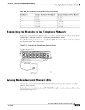
... wall telephone outlet. (See Figure 10-5.) Figure 10-5 Connecting an Analog Modem Network Module Analog modem port (RJ-11) NM-16AM-V2 MODEMS 15 14 13 12 11 10 9 8 IN USE IN USE 7 6 5 4 3 2 1 0 EN Straight-through RJ-11 modular cable to connect the jack to the Telephone Network Table 10-1 16- Each...11 cable 95209 RJ-11 jack Analog Modem Network Module LEDs All network modules have an enable (EN) LED. To establish an analog connection, use (IN USE) LED that the module has passed its self-tests and is off-hook. (See Figure 10-6 and Figure 10-7.) OL-2485-20 Cisco ...
... wall telephone outlet. (See Figure 10-5.) Figure 10-5 Connecting an Analog Modem Network Module Analog modem port (RJ-11) NM-16AM-V2 MODEMS 15 14 13 12 11 10 9 8 IN USE IN USE 7 6 5 4 3 2 1 0 EN Straight-through RJ-11 modular cable to connect the jack to the Telephone Network Table 10-1 16- Each...11 cable 95209 RJ-11 jack Analog Modem Network Module LEDs All network modules have an enable (EN) LED. To establish an analog connection, use (IN USE) LED that the module has passed its self-tests and is off-hook. (See Figure 10-6 and Figure 10-7.) OL-2485-20 Cisco ...

