
Hardware Installation Guide
Page 145
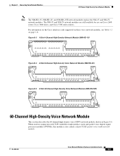
...NM-HD-1V) NM-HD -1V V0 EN 89033 Figure 8-4 2-Slot 8-Channel High-Density Voice Network Module (NM-HD-2V) NM-HD -2V V1 V0 EN 89034 Figure 8-5 2-Slot 48-Channel High-Density Voice Network Module (NM-HD-2VE) NM-HD -2VE V1 V0 EN...voice digital signal processor modules (PVDMs), this module is also called a digital T1/E1 packet voice trunk network module. OL-2485-20 Cisco Network Modules Hardware Installation Guide 8-3 For information on the Cisco interface cards supported on these voice network modules, see Table 1-2 on Cisco 2600 series, Cisco 3600 series, and Cisco 3700 series routers...
...NM-HD-1V) NM-HD -1V V0 EN 89033 Figure 8-4 2-Slot 8-Channel High-Density Voice Network Module (NM-HD-2V) NM-HD -2V V1 V0 EN 89034 Figure 8-5 2-Slot 48-Channel High-Density Voice Network Module (NM-HD-2VE) NM-HD -2VE V1 V0 EN...voice digital signal processor modules (PVDMs), this module is also called a digital T1/E1 packet voice trunk network module. OL-2485-20 Cisco Network Modules Hardware Installation Guide 8-3 For information on the Cisco interface cards supported on these voice network modules, see Table 1-2 on Cisco 2600 series, Cisco 3600 series, and Cisco 3700 series routers...
Hardware Installation Guide
Page 146
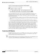
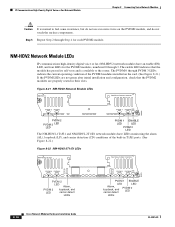
Currently, only the 1- In Cisco 3620 and Cisco 3640 routers, at least one or two T1/E1 line interfaces) can be installed starting from slot 0. Packet Voice DSP Modules The HDV network module contains five 72-pin SIMM sockets or banks for packet voice DSP modules (PVDMs), numbered 0 through 4. (See Figure 8-7.) Each socket can be installed in the...
Currently, only the 1- In Cisco 3620 and Cisco 3640 routers, at least one or two T1/E1 line interfaces) can be installed starting from slot 0. Packet Voice DSP Modules The HDV network module contains five 72-pin SIMM sockets or banks for packet voice DSP modules (PVDMs), numbered 0 through 4. (See Figure 8-7.) Each socket can be installed in the...
Hardware Installation Guide
Page 147
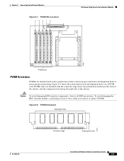
...-Density Voice Network Module 22955 PVDM slots PVDM Orientation PVDMs are installed with a polarization notch to ensure proper orientation and alignment holes to ensure proper positioning. To avoid damaging the HDV network module, avoid using excessive force when you remove or replace PVDMs. Figure 8-8 PVDM Orientation Alignment holes 22953 OL-2485-20 Connector edge Polarization notch Cisco Network...
...-Density Voice Network Module 22955 PVDM slots PVDM Orientation PVDMs are installed with a polarization notch to ensure proper orientation and alignment holes to ensure proper positioning. To avoid damaging the HDV network module, avoid using excessive force when you remove or replace PVDMs. Figure 8-8 PVDM Orientation Alignment holes 22953 OL-2485-20 Connector edge Polarization notch Cisco Network...
Hardware Installation Guide
Page 149
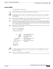
...card edges only. Ensure that each PVDM. Align the PVDM in Figure 8-9) line up with bank 0, insert the PVDM into the connector slot at an angle from front of board 1. Push the top of the chassis. OL-2485-20 Cisco Network Modules Hardware Installation Guide 8-7 The... not use excessive force on the PVDM and do not touch the surface components. Insert the PVDM into place. Chapter 8 Connecting Voice Network Modules 60-Channel High-Density Voice Network Module Installing PVDMs To install PVDMs, follow these steps: Step 1 Find the PVDM sockets on the HDV network module....
...card edges only. Ensure that each PVDM. Align the PVDM in Figure 8-9) line up with bank 0, insert the PVDM into the connector slot at an angle from front of board 1. Push the top of the chassis. OL-2485-20 Cisco Network Modules Hardware Installation Guide 8-7 The... not use excessive force on the PVDM and do not touch the surface components. Insert the PVDM into place. Chapter 8 Connecting Voice Network Modules 60-Channel High-Density Voice Network Module Installing PVDMs To install PVDMs, follow these steps: Step 1 Find the PVDM sockets on the HDV network module....
Hardware Installation Guide
Page 150
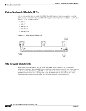
The BANK 0 through 4. The enable LED indicates that the PVDMs are properly seated in their slots. Cisco Network Modules Hardware Installation Guide 8-8 OL-2485-20 This LED indicates that the module has passed its self-tests and is available to the router. The following network modules have no additional LEDs. (See... • NM-1V • NM-2V • NM-HD-1V • NM-HD-2V • NM-HD-2VE Figure 8-11 Voice Network Module LED VOICE 2V Module screw V1 V0 EN H10833 Module screw Enable LED HDV Network Module LEDs High-density network modules have an enable (EN) LED.
The BANK 0 through 4. The enable LED indicates that the PVDMs are properly seated in their slots. Cisco Network Modules Hardware Installation Guide 8-8 OL-2485-20 This LED indicates that the module has passed its self-tests and is available to the router. The following network modules have no additional LEDs. (See... • NM-1V • NM-2V • NM-HD-1V • NM-HD-2V • NM-HD-2VE Figure 8-11 Voice Network Module LED VOICE 2V Module screw V1 V0 EN H10833 Module screw Enable LED HDV Network Module LEDs High-density network modules have an enable (EN) LED.
Hardware Installation Guide
Page 151
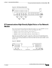
... two built-in T1/E1 ports, shown in Figure 8-15 These three base-board SKUs also include a single VIC or VWIC slot for Foreign Exchange Station (FXS), Foreign Exchange Office (FXO) or centralized automated message accounting trunk protocol (CAMA), receive and transmit ... 3 BANK 1 LED LED V0 EH ENABLE LED 22161 IP Communications High-Density Digital Voice or Fax Network Module This section describes the IP communications high-density digital voice or fax (NM-HDV2) network module. PVDM 3 PVDM 2 V0 PVDM 1 PVDM 0 EN 95196 OL-2485-20 Cisco Network Modules Hardware Installation Guide 8-9
... two built-in T1/E1 ports, shown in Figure 8-15 These three base-board SKUs also include a single VIC or VWIC slot for Foreign Exchange Station (FXS), Foreign Exchange Office (FXO) or centralized automated message accounting trunk protocol (CAMA), receive and transmit ... 3 BANK 1 LED LED V0 EH ENABLE LED 22161 IP Communications High-Density Digital Voice or Fax Network Module This section describes the IP communications high-density digital voice or fax (NM-HDV2) network module. PVDM 3 PVDM 2 V0 PVDM 1 PVDM 0 EN 95196 OL-2485-20 Cisco Network Modules Hardware Installation Guide 8-9
Hardware Installation Guide
Page 158
...Voice or Fax Network Module Chapter 8 Connecting Voice Network Modules Caution It is available to feel some resistance, but do not use excessive force on the card. (See Figure 8-21.) If the PVDM... normal to the router. The PVDM 0 through 3. PVDM 3 PVDM 2 V0 PVDM 1 PVDM 0 EN 103881 PVDM 2 PVDM 3 LED LED PVDM 1 ENABLE LED LED PVDM 0 LED The ...PVDM 3 PVDM 2 LP CD CTRLR T1/E1 1 PVDM 2 LED Alarm, PVDM 3 loopback, and LED carrier detect LEDs V0 AL LP CD CTRLR T1/E1 0 PVDM 1 PVDM 0 EN PVDM 1 ENABLE LED LED Alarm, loopback, and carrier detect PVDM 0 LED LEDs 8-16 Cisco...
...Voice or Fax Network Module Chapter 8 Connecting Voice Network Modules Caution It is available to feel some resistance, but do not use excessive force on the card. (See Figure 8-21.) If the PVDM... normal to the router. The PVDM 0 through 3. PVDM 3 PVDM 2 V0 PVDM 1 PVDM 0 EN 103881 PVDM 2 PVDM 3 LED LED PVDM 1 ENABLE LED LED PVDM 0 LED The ...PVDM 3 PVDM 2 LP CD CTRLR T1/E1 1 PVDM 2 LED Alarm, PVDM 3 loopback, and LED carrier detect LEDs V0 AL LP CD CTRLR T1/E1 0 PVDM 1 PVDM 0 EN PVDM 1 ENABLE LED LED Alarm, loopback, and carrier detect PVDM 0 LED LEDs 8-16 Cisco...