User Guide
Page 4
... does not fit into the apparatus, the apparatus has been exposed to your home or business, consult your service provider or your safety. Power Source Warning A label on the product label. Operate this product only from being walked on the unit must remain accessible and operable at plugs... with the manufacturer's instructions. 8) Do not install near water. 6) Clean only with dry cloth. 7) Do not block any heat sources such as a power-supply cord or plug is required when the apparatus has been damaged in any way, such as radiators, heat registers, stoves, or other . The wide...
... does not fit into the apparatus, the apparatus has been exposed to your home or business, consult your service provider or your safety. Power Source Warning A label on the product label. Operate this product only from being walked on the unit must remain accessible and operable at plugs... with the manufacturer's instructions. 8) Do not install near water. 6) Clean only with dry cloth. 7) Do not block any heat sources such as a power-supply cord or plug is required when the apparatus has been damaged in any way, such as radiators, heat registers, stoves, or other . The wide...
User Guide
Page 5
...before cleaning. WARNING: Avoid electric shock and fire hazard! Do not use a magnetic/static cleaning device (dust remover) to clean this product before applying power to the product. ƒ Do not place this apparatus on a bed, sofa, rug, or similar surface. ƒ Do not place this apparatus... this product. Do not use a liquid cleaner or an aerosol cleaner. Opening or removing the cover may still be connected to the power source. This product contains no user-serviceable parts. 4021196 Rev A 5 IMPORTANT SAFETY INSTRUCTIONS Protect the Product from Lightning In addition to disconnecting ...
...before cleaning. WARNING: Avoid electric shock and fire hazard! Do not use a magnetic/static cleaning device (dust remover) to clean this product before applying power to the product. ƒ Do not place this apparatus on a bed, sofa, rug, or similar surface. ƒ Do not place this apparatus... this product. Do not use a liquid cleaner or an aerosol cleaner. Opening or removing the cover may still be connected to the power source. This product contains no user-serviceable parts. 4021196 Rev A 5 IMPORTANT SAFETY INSTRUCTIONS Protect the Product from Lightning In addition to disconnecting ...
User Guide
Page 6
Protect the Product When Moving It Always disconnect the power source when moving the apparatus or connecting or disconnecting cables. 20090915_Modem No Battery_Safety 6 4021196 Rev A IMPORTANT SAFETY INSTRUCTIONS Check Product Safety Upon completion of any service or repairs to this product, the service technician must perform safety checks to determine that this product is in proper operating condition.
Protect the Product When Moving It Always disconnect the power source when moving the apparatus or connecting or disconnecting cables. 20090915_Modem No Battery_Safety 6 4021196 Rev A IMPORTANT SAFETY INSTRUCTIONS Check Product Safety Upon completion of any service or repairs to this product, the service technician must perform safety checks to determine that this product is in proper operating condition.
User Guide
Page 10
...Information section of the appropriate product hardware installation guide, which is used in dBi) to 10 mW EIRP when the product is available on Cisco.com. Please check http://www.comunicazioni.it/it / per maggiori dettagli. Latvia The outdoor usage of the Directive 1999/5/EC: ƒ .... Italy This product meets the National Radio Interface and the requirements specified in Italia. Please check http://www.esd.lv for maximum output power are affixed to the following standards were applied during the assessment of the product against the requirements of the 2.4 GHz band requires an ...
...Information section of the appropriate product hardware installation guide, which is used in dBi) to 10 mW EIRP when the product is available on Cisco.com. Please check http://www.comunicazioni.it/it / per maggiori dettagli. Latvia The outdoor usage of the Directive 1999/5/EC: ƒ .... Italy This product meets the National Radio Interface and the requirements specified in Italia. Please check http://www.esd.lv for maximum output power are affixed to the following standards were applied during the assessment of the product against the requirements of the 2.4 GHz band requires an ...
User Guide
Page 14
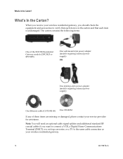
... carton contains the following items: One of the DOCSIS Residential Gateway models (DPC3825 or EPC3825) One wall-mount style power adapter (models requiring external power supply) OR One desktop-style power adapter (models requiring external power supply) One Ethernet cable (CAT5/RJ-45) One CD-ROM If any of these items are missing or...
... carton contains the following items: One of the DOCSIS Residential Gateway models (DPC3825 or EPC3825) One wall-mount style power adapter (models requiring external power supply) OR One desktop-style power adapter (models requiring external power supply) One Ethernet cable (CAT5/RJ-45) One CD-ROM If any of these items are missing or...
User Guide
Page 15
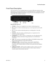
... of your residential gateway provides LED status indicators that indicate how well and at what state your residential gateway is operational. Model DPC3825 shown here 1 POWER-ON, power is applied to the wireless residential gateway 2 DS-ON, the wireless residential gateway is receiving data from the cable network 3 US-On, the wireless...
... of your residential gateway provides LED status indicators that indicate how well and at what state your residential gateway is operational. Model DPC3825 shown here 1 POWER-ON, power is applied to the wireless residential gateway 2 DS-ON, the wireless residential gateway is receiving data from the cable network 3 US-On, the wireless...
User Guide
Page 16
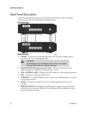
...Connects to selected client devices 5 ETHERNET-Four RJ-45 Ethernet ports connect to the Ethernet port on the Cisco DPC3825 residential gateway. 1 POWER-Connects the residential gateway to the AC power adapter that is provided with your residential gateway CAUTION: Avoid damage to your service provider 7 WIRELESS SETUP... that is provided with your residential gateway. 2 ON/OFF SWITCH (European models only)-Allows you to power of the residential gateway without removing the power cord 3 MAC ADDRESS LABEL-Displays the MAC address of the back panel components on your PC or your home network...
...Connects to selected client devices 5 ETHERNET-Four RJ-45 Ethernet ports connect to the Ethernet port on the Cisco DPC3825 residential gateway. 1 POWER-Connects the residential gateway to the AC power adapter that is provided with your residential gateway CAUTION: Avoid damage to your service provider 7 WIRELESS SETUP... that is provided with your residential gateway. 2 ON/OFF SWITCH (European models only)-Allows you to power of the residential gateway without removing the power cord 3 MAC ADDRESS LABEL-Displays the MAC address of the back panel components on your PC or your home network...
User Guide
Page 24
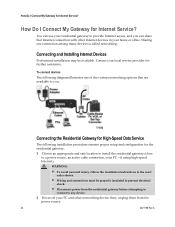
... or office. Connecting and Installing Internet Devices Professional installation may be properly insulated to prevent electrical shock. ƒ Disconnect power from the power source. 24 4021196 Rev A Connecting the Residential Gateway for Internet Service? then, unplug them from the residential gateway before... many devices is called networking. Contact your PC-if using high-speed Internet). You can share that are available to a power source, an active cable connection, your local service provider for the residential gateway. 1 Choose an appropriate and safe location to...
... or office. Connecting and Installing Internet Devices Professional installation may be properly insulated to prevent electrical shock. ƒ Disconnect power from the power source. 24 4021196 Rev A Connecting the Residential Gateway for Internet Service? then, unplug them from the residential gateway before... many devices is called networking. Contact your PC-if using high-speed Internet). You can share that are available to a power source, an active cable connection, your local service provider for the residential gateway. 1 Choose an appropriate and safe location to...
User Guide
Page 25
...the factory default configuration of your wireless gateway can be found later in this user guide in and power on your PC and other than ports provided on the residential gateway, use when the POWER, DS, US and ONLINE LEDs on the front panel of the residential gateway stop blinking and ... coax connector labeled CABLE on your residential gateway. You will be on the back of the power cord into an AC outlet to the yellow ETHERNET port on or blinking. 7 Once the residential gateway is powered up to install a cable signal splitter (not included). Insert one end of the Ethernet cable...
...the factory default configuration of your wireless gateway can be found later in this user guide in and power on your PC and other than ports provided on the residential gateway, use when the POWER, DS, US and ONLINE LEDs on the front panel of the residential gateway stop blinking and ... coax connector labeled CABLE on your residential gateway. You will be on the back of the power cord into an AC outlet to the yellow ETHERNET port on or blinking. 7 Once the residential gateway is powered up to install a cable signal splitter (not included). Insert one end of the Ethernet cable...
User Guide
Page 90
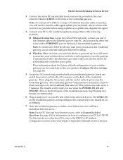
... is a unique alphanumeric address for the cable modem coaxial interface, which is a hardware address that uniquely identifies each node of the gateway Channels 1-8 Displays the power level and the signal to the CMTS at the headend. Monitor Gateway Status Section Downstream Channels Upstream Channels Field Description MAC Address (CM MAC Address... one of the possible current states of a network. A MAC address is used to connect to noise ratio of the active downstream channels Channels 1-4 Displays the power level of the active upstream channels 90 4021196 Rev A
... is a unique alphanumeric address for the cable modem coaxial interface, which is a hardware address that uniquely identifies each node of the gateway Channels 1-8 Displays the power level and the signal to the CMTS at the headend. Monitor Gateway Status Section Downstream Channels Upstream Channels Field Description MAC Address (CM MAC Address... one of the possible current states of a network. A MAC address is used to connect to noise ratio of the active downstream channels Channels 1-4 Displays the power level of the active upstream channels 90 4021196 Rev A
User Guide
Page 92
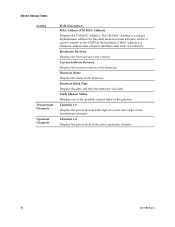
... Apple chime at the top of the Finder. If there is unchecked. 6 Verify that your Macintosh but do not release these keys until you must power off your Macintosh. 8 With the power off, simultaneously press and hold down...
... Apple chime at the top of the Finder. If there is unchecked. 6 Verify that your Macintosh but do not release these keys until you must power off your Macintosh. 8 With the power off, simultaneously press and hold down...
User Guide
Page 95
... to other devices, remove the splitter and reconnect the cables so that you need to your residential gateway AC power is properly inserted into an electrical outlet that your residential gateway AC power cord is connected directly to the cable input. Verify that your cable service is controlled by a wall switch. If...
... to other devices, remove the splitter and reconnect the cables so that you need to your residential gateway AC power is properly inserted into an electrical outlet that your residential gateway AC power cord is connected directly to the cable input. Verify that your cable service is controlled by a wall switch. If...
User Guide
Page 96
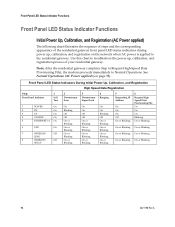
... High-Speed Data Provisioning File), the modem proceeds immediately to troubleshoot the power up , calibration, and registration on page 98). See Normal Operations (AC Power applied) (on the network when AC power is applied to the residential gateway. Front Panel LED Status Indicators During ...Blinking 96 4021196 Rev A Front Panel LED Status Indicator Functions Front Panel LED Status Indicator Functions Initial Power Up, Calibration, and Registration (AC Power applied) The following chart illustrates the sequence of steps and the corresponding appearance of the residential gateway ...
... High-Speed Data Provisioning File), the modem proceeds immediately to troubleshoot the power up , calibration, and registration on page 98). See Normal Operations (AC Power applied) (on the network when AC power is applied to the residential gateway. Front Panel LED Status Indicators During ...Blinking 96 4021196 Rev A Front Panel LED Status Indicator Functions Front Panel LED Status Indicator Functions Initial Power Up, Calibration, and Registration (AC Power applied) The following chart illustrates the sequence of steps and the corresponding appearance of the residential gateway ...
User Guide
Page 97
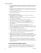
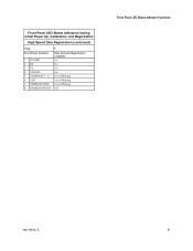
Front Panel LED Status Indicators During Initial Power Up, Calibration, and Registration High Speed Data Registration (continued) Step Front Panel Indicator 1 POWER 2 DS 3 US 4 ONLINE 5 ETHERNET 1 - 4 6 USB 7 WIRELESS LINK 8 WIRELESS SETUP 7 Data Network Registration Complete On On On On On or Blinking On or Blinking On or Blinking Off Front Panel LED Status Indicator Functions 4021196 Rev A 97
Front Panel LED Status Indicators During Initial Power Up, Calibration, and Registration High Speed Data Registration (continued) Step Front Panel Indicator 1 POWER 2 DS 3 US 4 ONLINE 5 ETHERNET 1 - 4 6 USB 7 WIRELESS LINK 8 WIRELESS SETUP 7 Data Network Registration Complete On On On On On or Blinking On or Blinking On or Blinking Off Front Panel LED Status Indicator Functions 4021196 Rev A 97
User Guide
Page 98
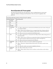
...; On - When wireless setup is being sent 1 - 4 to the gateway. Front Panel LED Status Indicator Functions Normal Operations (AC Power applied) The following chart illustrates the appearance of the residential gateway front panel LED status indicators during normal operations when AC... premise equipment (CPE) and the wireless home gateway ƒ Off - Front Panel LED Status Indicators During Normal Conditions Front Panel Indicator Normal Operations 1 POWER On 2 DS On 3 US On 4 ONLINE On 5 ETHERNET ƒ On - When no data is active to or from the modem ƒ...
...; On - When wireless setup is being sent 1 - 4 to the gateway. Front Panel LED Status Indicator Functions Normal Operations (AC Power applied) The following chart illustrates the appearance of the residential gateway front panel LED status indicators during normal operations when AC... premise equipment (CPE) and the wireless home gateway ƒ Off - Front Panel LED Status Indicators During Normal Conditions Front Panel Indicator Normal Operations 1 POWER On 2 DS On 3 US On 4 ONLINE On 5 ETHERNET ƒ On - When no data is active to or from the modem ƒ...
User Guide
Page 99
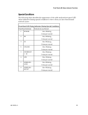
... special conditions to show when you have been denied network access. Front Panel LED Status Indicators During Special Conditions Front Panel Indicator Network Access Denied 1 POWER Slow Blinking 1 time per second 2 DS Slow Blinking 1 time per second 3 US Slow Blinking 1 time per second 4 ONLINE Slow Blinking 1 time per second 5 ETHERNET 1 - 44...
... special conditions to show when you have been denied network access. Front Panel LED Status Indicators During Special Conditions Front Panel Indicator Network Access Denied 1 POWER Slow Blinking 1 time per second 2 DS Slow Blinking 1 time per second 3 US Slow Blinking 1 time per second 4 ONLINE Slow Blinking 1 time per second 5 ETHERNET 1 - 44...
Hardware Installation Guide
Page 39
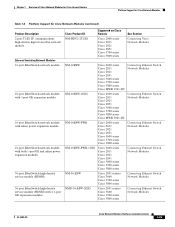
... GE and inline power expansion modules 36-port EtherSwitch high-density service module (HDSM) 36-port EtherSwitch high-density service module (HDSM) with 2 1-port GE expansion modules Cisco Product ID NM-HDV2-2T1/E1 Supported on Cisco Routers Cisco 2600 series Cisco 2811 Cisco 2821 Cisco 2851 Cisco 3700 series Cisco 3800 series See Section Connecting Voice Network Modules NM-16ESW...
... GE and inline power expansion modules 36-port EtherSwitch high-density service module (HDSM) 36-port EtherSwitch high-density service module (HDSM) with 2 1-port GE expansion modules Cisco Product ID NM-HDV2-2T1/E1 Supported on Cisco Routers Cisco 2600 series Cisco 2811 Cisco 2821 Cisco 2851 Cisco 3700 series Cisco 3800 series See Section Connecting Voice Network Modules NM-16ESW...
Hardware Installation Guide
Page 40
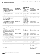
Platform Support for Cisco Network Modules Chapter 1 Overview of Cisco Network Modules for Cisco Access Routers Table 1-6 Platform Support for Cisco Network Modules (continued) Product Description Cisco Product ID Supported on Cisco Routers 36-port EtherSwitch high-density service module (HDSM) with inline power expansion module NMD-36-ESW-PWR Cisco 2851 routers Cisco 3660 Cisco 3700 series Cisco 3800 series 36-port EtherSwitch high...
Platform Support for Cisco Network Modules Chapter 1 Overview of Cisco Network Modules for Cisco Access Routers Table 1-6 Platform Support for Cisco Network Modules (continued) Product Description Cisco Product ID Supported on Cisco Routers 36-port EtherSwitch high-density service module (HDSM) with inline power expansion module NMD-36-ESW-PWR Cisco 2851 routers Cisco 3660 Cisco 3700 series Cisco 3800 series 36-port EtherSwitch high...
Hardware Installation Guide
Page 50
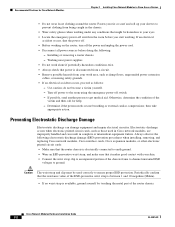
... Cisco Network Modules Chapter 2 Installing Cisco Network Modules in Cisco network modules, are improperly handled and can damage equipment and impair electrical circuitry. Recommended Practices for help. - Fasten your tie or scarf and roll up your sleeves to ground. Installing or removing a router chassis - Turn off the power and unplug the power cord. • Disconnect all power...
... Cisco Network Modules Chapter 2 Installing Cisco Network Modules in Cisco network modules, are improperly handled and can damage equipment and impair electrical circuitry. Recommended Practices for help. - Fasten your tie or scarf and roll up your sleeves to ground. Installing or removing a router chassis - Turn off the power and unplug the power cord. • Disconnect all power...

Hardware Installation Guide
Page 51
... this product should be handled according to all hardware procedures involving Cisco network modules for Cisco access routers. Statement 1030 Warning Ultimate disposal of the chassis. For systems without a power switch, line voltages are required to lift the chassis. Warning ... of these warnings are present within the power supply when the power cord is connected. Chapter 2 Installing Cisco Network Modules in Cisco Access Routers Recommended Practices for Cisco Network Modules General Maintenance Guidelines for Cisco Network Modules The following safety warning statements ...
... this product should be handled according to all hardware procedures involving Cisco network modules for Cisco access routers. Statement 1030 Warning Ultimate disposal of the chassis. For systems without a power switch, line voltages are required to lift the chassis. Warning ... of these warnings are present within the power supply when the power cord is connected. Chapter 2 Installing Cisco Network Modules in Cisco Access Routers Recommended Practices for Cisco Network Modules General Maintenance Guidelines for Cisco Network Modules The following safety warning statements ...


