
Hardware Installation Guide
Page 12
Contents E A P P E N D I X INDEX Translated Safety Warnings E-1 Attaching the Cisco RPS (model PWR300-AC-RPS-N1) E-1 Attaching the Cisco RPS (model PWR675-AC-RPS-N1) E-2 Installation Warning E-4 Installation Instructions E-5 Jewelry Removal Warning E-6 Stacking the Chassis Warning E-8 ... Chassis Warning for Rack-Mounting and Servicing E-19 Redundant Power Supply Connection Warning E-24 Switch Installation Warning E-25 Restricted Area E-27 Ethernet Cable Shielding in Offices E-28 Laser Beam Exposure E-30 Laser Radiation E-31 E-32 Catalyst 3750 Switch Hardware Installation Guide x 78-15136-02
Contents E A P P E N D I X INDEX Translated Safety Warnings E-1 Attaching the Cisco RPS (model PWR300-AC-RPS-N1) E-1 Attaching the Cisco RPS (model PWR675-AC-RPS-N1) E-2 Installation Warning E-4 Installation Instructions E-5 Jewelry Removal Warning E-6 Stacking the Chassis Warning E-8 ... Chassis Warning for Rack-Mounting and Servicing E-19 Redundant Power Supply Connection Warning E-24 Switch Installation Warning E-25 Restricted Area E-27 Ethernet Cable Shielding in Offices E-28 Laser Beam Exposure E-30 Laser Radiation E-31 E-32 Catalyst 3750 Switch Hardware Installation Guide x 78-15136-02

Hardware Installation Guide
Page 42
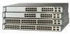
...Catalyst 3750 switches, 1000BASE-T small form-factor pluggable (SFP) modules can stack up to the Catalyst 3750-24TS, 3750G-24T, 3750-48TS, and 3750G-12S switches. Catalyst 3750-48TS-48 10/100 Ethernet ports and 4 SFP module slots - Catalyst 3750G-24T-24 10/100/1000 Ethernet ports - Catalyst 3750G-24TS... ports. Connection for optional Cisco RPS 300 redundant power system that operates on AC input and supplies backup DC power output to nine switches in half-duplex mode at 10 or 100 Mbps. • Configuration - Catalyst 3750 Switch Hardware Installation Guide 2-2 78...
...Catalyst 3750 switches, 1000BASE-T small form-factor pluggable (SFP) modules can stack up to the Catalyst 3750-24TS, 3750G-24T, 3750-48TS, and 3750G-12S switches. Catalyst 3750-48TS-48 10/100 Ethernet ports and 4 SFP module slots - Catalyst 3750G-24T-24 10/100/1000 Ethernet ports - Catalyst 3750G-24TS... ports. Connection for optional Cisco RPS 300 redundant power system that operates on AC input and supplies backup DC power output to nine switches in half-duplex mode at 10 or 100 Mbps. • Configuration - Catalyst 3750 Switch Hardware Installation Guide 2-2 78...

Hardware Installation Guide
Page 43
.../100/1000 ports on AC input and supplies backup DC power output to 28. 78-15136-02 Catalyst 3750 Switch Hardware Installation Guide 2-3 In Figure 2-3 the SFP port are grouped in pairs. Chapter 2 Product Overview Front Panel Description Note The Cisco RPS 300 does not support the Catalyst 3750G-24TS switch. - Front Panel Description The Catalyst 3750-24TS 10/100 ports are...
.../100/1000 ports on AC input and supplies backup DC power output to 28. 78-15136-02 Catalyst 3750 Switch Hardware Installation Guide 2-3 In Figure 2-3 the SFP port are grouped in pairs. Chapter 2 Product Overview Front Panel Description Note The Cisco RPS 300 does not support the Catalyst 3750G-24TS switch. - Front Panel Description The Catalyst 3750-24TS 10/100 ports are...

Hardware Installation Guide
Page 56
... maximum output power of switches. Cisco RPS Connector Specific Cisco RPS modes support specific Catalyst 3750 switches: • Cisco RPS 300 (model PWR300-AC-RPS-N1) supports the Catalyst 3750-24TS, 3750G-24T, 3750G-12S, and 3750-48TS switches. • Cisco RPS 675 (model PWR675-AC-RPS-N1=) supports the Catalyst 3750 family of 300W. Note The Cisco RPS 300 does not support the Catalyst 3750G-24TS switches. Use the supplied RPS connector...
... maximum output power of switches. Cisco RPS Connector Specific Cisco RPS modes support specific Catalyst 3750 switches: • Cisco RPS 300 (model PWR300-AC-RPS-N1) supports the Catalyst 3750-24TS, 3750G-24T, 3750G-12S, and 3750-48TS switches. • Cisco RPS 675 (model PWR675-AC-RPS-N1=) supports the Catalyst 3750 family of 300W. Note The Cisco RPS 300 does not support the Catalyst 3750G-24TS switches. Use the supplied RPS connector...

Hardware Installation Guide
Page 57
... when the internal power supply of network traffic. You can order a kit (part number ACS-DSBUASYN=) containing that can support six external network devices and provides power to the Cisco RPS 675 Redundant Power System Hardware Installation Guide. For more information on the Cisco RPS 300, refer..."Connector and Cable Specifications" section on the Cisco RPS 675, refer to one failed device at a time. It automatically senses when the internal power supply of 675W. For more information on page B-1. 78-15136-02 Catalyst 3750 Switch Hardware Installation Guide 2-17 If you want...
... when the internal power supply of network traffic. You can order a kit (part number ACS-DSBUASYN=) containing that can support six external network devices and provides power to the Cisco RPS 675 Redundant Power System Hardware Installation Guide. For more information on the Cisco RPS 300, refer..."Connector and Cable Specifications" section on the Cisco RPS 675, refer to one failed device at a time. It automatically senses when the internal power supply of 675W. For more information on page B-1. 78-15136-02 Catalyst 3750 Switch Hardware Installation Guide 2-17 If you want...

Hardware Installation Guide
Page 68
... to the Console Port To connect a PC to the console port, use the supplied RJ-45-to -DB-25 female DTE adapter. Note If you should power the switch and verify that adapter from Cisco. One cable guide and one black Phillips machine screw for attaching the brackets to the switch (Catalyst 3750-24TS, 3750G-24T, and 3750-48TS...
... to the Console Port To connect a PC to the console port, use the supplied RJ-45-to -DB-25 female DTE adapter. Note If you should power the switch and verify that adapter from Cisco. One cable guide and one black Phillips machine screw for attaching the brackets to the switch (Catalyst 3750-24TS, 3750G-24T, and 3750-48TS...
Hardware Installation Guide
Page 153
... a terminal-emulation session. Note If you are using a PC or terminal. Connect the other end of the supplied AC power cord to the "Powering Considerations" section on page 3-13 for more information. 78-15136-02 Catalyst 3750 Switch Hardware Installation Guide D-9 Appendix D Quick Setup By Using the CLI-Based Setup Program Starting the Terminal Emulation Software...
... a terminal-emulation session. Note If you are using a PC or terminal. Connect the other end of the supplied AC power cord to the "Powering Considerations" section on page 3-13 for more information. 78-15136-02 Catalyst 3750 Switch Hardware Installation Guide D-9 Appendix D Quick Setup By Using the CLI-Based Setup Program Starting the Terminal Emulation Software...
Hardware Installation Guide
Page 195
...numbering of 10/100 2-6 numbering of 10/100/1000 2-6 POST LEDs 4-2 results 4-1 running at powerup 1-4 power connecting to 3-10 connectors 2-14, 2-16 specifications A-1 to A-5 power on 3-10 power supply AC power outlet 2-16 RPS connector 2-16 procedures connection 3-44 to 3-48 installation 3-17 to 3-36 product disposal ... qualified personnel warning E-4 R rack-mounting 3-18 to 3-36 rear panel clearance 3-6 description 2-14 to 2-17 redundant power supply See RPS regulatory statements, EMC 3-4 removing SFP modules 3-43 to 3-44 78-15136-02 Catalyst 3750 Switch Hardware Installation Guide IN-5
...numbering of 10/100 2-6 numbering of 10/100/1000 2-6 POST LEDs 4-2 results 4-1 running at powerup 1-4 power connecting to 3-10 connectors 2-14, 2-16 specifications A-1 to A-5 power on 3-10 power supply AC power outlet 2-16 RPS connector 2-16 procedures connection 3-44 to 3-48 installation 3-17 to 3-36 product disposal ... qualified personnel warning E-4 R rack-mounting 3-18 to 3-36 rear panel clearance 3-6 description 2-14 to 2-17 redundant power supply See RPS regulatory statements, EMC 3-4 removing SFP modules 3-43 to 3-44 78-15136-02 Catalyst 3750 Switch Hardware Installation Guide IN-5

