
Hardware Installation Guide
Page 9
... Powering Considerations 3-13 Cabling Considerations 3-14 Recommended Cabling Configurations 3-15 Installing the Switch 3-17 Rack Mounting 3-18 Removing Screws from the Switch 3-19 Attaching Brackets to the Catalyst 3750G-24TS Switch 3-20 Attaching Brackets to the Catalyst 3750-24TS, 3750G-24T, 3750G-12S, and 3750-48TS Switches 3-25 Mounting the Switch in a Rack 3-28 Attaching the Cable Guide 3-30 Wall Mounting 3-32 Attaching...
... Powering Considerations 3-13 Cabling Considerations 3-14 Recommended Cabling Configurations 3-15 Installing the Switch 3-17 Rack Mounting 3-18 Removing Screws from the Switch 3-19 Attaching Brackets to the Catalyst 3750G-24TS Switch 3-20 Attaching Brackets to the Catalyst 3750-24TS, 3750G-24T, 3750G-12S, and 3750-48TS Switches 3-25 Mounting the Switch in a Rack 3-28 Attaching the Cable Guide 3-30 Wall Mounting 3-32 Attaching...

Hardware Installation Guide
Page 42
... 100 Mbps. • Configuration - Connection for optional Cisco RPS 300 redundant power system that operates on AC input and supplies backup DC power output to nine switches in Catalyst 3750 switches, 1000BASE-T small form-factor pluggable (SFP) modules can stack up to the Catalyst 3750-24TS, 3750G-24T, 3750-48TS, and 3750G-12S switches. Catalyst 3750-24TS-24 10/100 Ethernet ports and 2 small...
... 100 Mbps. • Configuration - Connection for optional Cisco RPS 300 redundant power system that operates on AC input and supplies backup DC power output to nine switches in Catalyst 3750 switches, 1000BASE-T small form-factor pluggable (SFP) modules can stack up to the Catalyst 3750-24TS, 3750G-24T, 3750-48TS, and 3750G-12S switches. Catalyst 3750-24TS-24 10/100 Ethernet ports and 2 small...

Hardware Installation Guide
Page 43
... numbers are numbered 1 (left , as shown in pairs. The first member of Catalyst 3750 switches. Port 3 is above port 4, and so on AC input and supplies backup DC power output to 28. 78-15136-02 Catalyst 3750 Switch Hardware Installation Guide 2-3 Chapter 2 Product Overview Front Panel Description Note The Cisco RPS 300 does not support the Catalyst 3750G-24TS switch. -
... numbers are numbered 1 (left , as shown in pairs. The first member of Catalyst 3750 switches. Port 3 is above port 4, and so on AC input and supplies backup DC power output to 28. 78-15136-02 Catalyst 3750 Switch Hardware Installation Guide 2-3 Chapter 2 Product Overview Front Panel Description Note The Cisco RPS 300 does not support the Catalyst 3750G-24TS switch. -

Hardware Installation Guide
Page 44
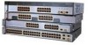
... 9 10 11 12 11X 2X 12X 13 14 13X 15 16 17 18 19 20 21 22 23 24 23X 14X 24X 1 Catalyst 3750 SERIES 1 10/100/1000 ports Figure 2-3 Catalyst 3750G-24TS Front Panel Chapter 2 Product Overview 86543 86544 SYST RPS MASTR STAT DUPLX SPEED STACK MODE 12 1X 34 56 78 9 10... 12X 13 14 13X 15 16 17 18 19 20 21 22 23 24 23X 14X 24X Catalyst 3750 SERIES 25 26 27 28 1 2 1 10/100 ports 2 SFP module ports The Catalyst 3750G-12S SFP module slots are grouped in three sets of four, as shown in Figure 2-4. Catalyst 3750 Switch Hardware Installation Guide 2-4 78-15136-02
... 9 10 11 12 11X 2X 12X 13 14 13X 15 16 17 18 19 20 21 22 23 24 23X 14X 24X 1 Catalyst 3750 SERIES 1 10/100/1000 ports Figure 2-3 Catalyst 3750G-24TS Front Panel Chapter 2 Product Overview 86543 86544 SYST RPS MASTR STAT DUPLX SPEED STACK MODE 12 1X 34 56 78 9 10... 12X 13 14 13X 15 16 17 18 19 20 21 22 23 24 23X 14X 24X Catalyst 3750 SERIES 25 26 27 28 1 2 1 10/100 ports 2 SFP module ports The Catalyst 3750G-12S SFP module slots are grouped in three sets of four, as shown in Figure 2-4. Catalyst 3750 Switch Hardware Installation Guide 2-4 78-15136-02

Hardware Installation Guide
Page 45
...The SFP port numbers are numbered 1 through 48. Chapter 2 Product Overview Figure 2-4 Catalyst 3750G-12S Front Panel Front Panel Description 97166 SYST RPS MASTR STAT DUPLX SPEED STACK MODE 1 2 3 4 5 6 7 8 9 10 Catalyst 3750 SERIES 11 12 1 1 SFP module ports The Catalyst 3750-48TS 10/100 ports are 1 (top) and 2 (bottom) and so on. Port ... 33X 35 36 37 38 39 40 41 42 43 44 45 46 47 48 47X 32X 34X 48X Catalyst 3750 SERIES 1 3 2 4 1 2 1 10/100 ports 2 SFP module ports 78-15136-02 Catalyst 3750 Switch Hardware Installation Guide 2-5 The ports are grouped in Figure 2-1.
...The SFP port numbers are numbered 1 through 48. Chapter 2 Product Overview Figure 2-4 Catalyst 3750G-12S Front Panel Front Panel Description 97166 SYST RPS MASTR STAT DUPLX SPEED STACK MODE 1 2 3 4 5 6 7 8 9 10 Catalyst 3750 SERIES 11 12 1 1 SFP module ports The Catalyst 3750-48TS 10/100 ports are 1 (top) and 2 (bottom) and so on. Port ... 33X 35 36 37 38 39 40 41 42 43 44 45 46 47 48 47X 32X 34X 48X Catalyst 3750 SERIES 1 3 2 4 1 2 1 10/100 ports 2 SFP module ports 78-15136-02 Catalyst 3750 Switch Hardware Installation Guide 2-5 The ports are grouped in Figure 2-1.

Hardware Installation Guide
Page 48
... LED 5 Status LED 6 Master LED 7 RPS LED 8 System LED 9 Port LED 86545 Catalyst 3750 Switch Hardware Installation Guide 2-8 78-15136-02 Figure 2-6 shows the Catalyst 3750-24TS, 3750G-24T, 3750G-24TS, 3750G-12S, and 3750-48TS LEDs and the Mode button that you use the switch LEDs to monitor switch activity and its performance. Front Panel Description Chapter 2 Product Overview LEDs You...
... LED 5 Status LED 6 Master LED 7 RPS LED 8 System LED 9 Port LED 86545 Catalyst 3750 Switch Hardware Installation Guide 2-8 78-15136-02 Figure 2-6 shows the Catalyst 3750-24TS, 3750G-24T, 3750G-24TS, 3750G-12S, and 3750-48TS LEDs and the Mode button that you use the switch LEDs to monitor switch activity and its performance. Front Panel Description Chapter 2 Product Overview LEDs You...

Hardware Installation Guide
Page 50
... 300 does not support the Catalyst 3750G-24TS switches. Port LEDs and Modes Each RJ-45 port and SFP module slot has a port LED. Front Panel Description Chapter 2 Product Overview For more information about the Cisco RPS 300, refer to the Cisco RPS 300 Redundant Power System Hardware Installation ... When you change to the Cisco RPS 675 Redundant Power System Hardware Installation Guide. For example, if you press the Mode button on the stack master to interpret the port LED colors in the stack also display SPEED. 2-10 Catalyst 3750 Switch Hardware Installation Guide 78-15136-...
... 300 does not support the Catalyst 3750G-24TS switches. Port LEDs and Modes Each RJ-45 port and SFP module slot has a port LED. Front Panel Description Chapter 2 Product Overview For more information about the Cisco RPS 300, refer to the Cisco RPS 300 Redundant Power System Hardware Installation ... When you change to the Cisco RPS 675 Redundant Power System Hardware Installation Guide. For example, if you press the Mode button on the stack master to interpret the port LED colors in the stack also display SPEED. 2-10 Catalyst 3750 Switch Hardware Installation Guide 78-15136-...

Hardware Installation Guide
Page 53
... bandwidth (32 Gbps). Chapter 2 Product Overview Front Panel Description • SFP port LEDs 3 and 4 on the Catalyst 3750-48TS switch show the status for StackWise ports 1 and 2, respectively. • SFP port LEDs 27 and 28 on the Catalyst 3750G-24TS switch show the status for StackWise ports 1 and 2, respectively. • The 10/100/1000 port LEDs 23...
... bandwidth (32 Gbps). Chapter 2 Product Overview Front Panel Description • SFP port LEDs 3 and 4 on the Catalyst 3750-48TS switch show the status for StackWise ports 1 and 2, respectively. • SFP port LEDs 27 and 28 on the Catalyst 3750G-24TS switch show the status for StackWise ports 1 and 2, respectively. • The 10/100/1000 port LEDs 23...

Hardware Installation Guide
Page 54
... two StackWise ports. (See Figure 2-8 and Figure 2-9.) Figure 2-8 Catalyst 3750-24TS, 3750G-24T, 3750G-12S, and 3750-48TS Rear Panel 86548 STACK 1 STACK 2 CONSOLE 1.6A-100R>09A-A2T0,IN05GV0-~60 HZ [email protected] 1 23 4 5 1 StackWise ports 2 RJ-45 console port 3 Fan exhaust 4 AC power connector 5 RPS connector 2-14 Catalyst 3750 Switch Hardware Installation Guide 78-15136-02
... two StackWise ports. (See Figure 2-8 and Figure 2-9.) Figure 2-8 Catalyst 3750-24TS, 3750G-24T, 3750G-12S, and 3750-48TS Rear Panel 86548 STACK 1 STACK 2 CONSOLE 1.6A-100R>09A-A2T0,IN05GV0-~60 HZ [email protected] 1 23 4 5 1 StackWise ports 2 RJ-45 console port 3 Fan exhaust 4 AC power connector 5 RPS connector 2-14 Catalyst 3750 Switch Hardware Installation Guide 78-15136-02

Hardware Installation Guide
Page 55
... Figure 2-9 Catalyst 3750G-24TS Rear Panel Rear Panel Description 86547 STACK 1 STACK 2 CONSOLE DSCPIENPCPO+IUWF1TI2EESvDRFISO@NUR1MP7RPAaELNYMUOATLE 1 23 4 5 1 StackWise ports 2 RJ-45 console port 3 Fan exhaust 4 AC power connector 5 RPS connector StackWise Ports The Catalyst 3750 switch ships with a 0.5-meter StackWise cable (72-2632-XX CABASY) that you can order these StackWise cables from your Cisco sales...
... Figure 2-9 Catalyst 3750G-24TS Rear Panel Rear Panel Description 86547 STACK 1 STACK 2 CONSOLE DSCPIENPCPO+IUWF1TI2EESvDRFISO@NUR1MP7RPAaELNYMUOATLE 1 23 4 5 1 StackWise ports 2 RJ-45 console port 3 Fan exhaust 4 AC power connector 5 RPS connector StackWise Ports The Catalyst 3750 switch ships with a 0.5-meter StackWise cable (72-2632-XX CABASY) that you can order these StackWise cables from your Cisco sales...

Hardware Installation Guide
Page 56
... (model PWR300-AC-RPS-N1) to an AC power outlet. Cisco RPS Connector Specific Cisco RPS modes support specific Catalyst 3750 switches: • Cisco RPS 300 (model PWR300-AC-RPS-N1) supports the Catalyst 3750-24TS, 3750G-24T, 3750G-12S, and 3750-48TS switches. • Cisco RPS 675 (model PWR675-AC-RPS-N1=) supports the Catalyst 3750 family of 300W. Rear Panel Description Chapter 2 Product Overview...
... (model PWR300-AC-RPS-N1) to an AC power outlet. Cisco RPS Connector Specific Cisco RPS modes support specific Catalyst 3750 switches: • Cisco RPS 300 (model PWR300-AC-RPS-N1) supports the Catalyst 3750-24TS, 3750G-24T, 3750G-12S, and 3750-48TS switches. • Cisco RPS 675 (model PWR675-AC-RPS-N1=) supports the Catalyst 3750 family of 300W. Rear Panel Description Chapter 2 Product Overview...
Hardware Installation Guide
Page 67
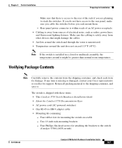
...switches. Note If the switch is shipped with these items: • This Catalyst 3750 Switch Hardware Installation Guide • About the Catalyst 3750 Documentation flyer • AC power cord (AC-powered switches) • One RJ-45-to the switch (Catalyst 3750G-24TS switch) 78-15136-02 Catalyst 3750 Switch Hardware Installation Guide 3-7 The switch...item for damage. If any item is unrestricted. • Temperature around the switch and through the vents is missing or damaged, contact your Cisco representative or reseller for support. Rear-panel power connector is within reach of ...
...switches. Note If the switch is shipped with these items: • This Catalyst 3750 Switch Hardware Installation Guide • About the Catalyst 3750 Documentation flyer • AC power cord (AC-powered switches) • One RJ-45-to the switch (Catalyst 3750G-24TS switch) 78-15136-02 Catalyst 3750 Switch Hardware Installation Guide 3-7 The switch...item for damage. If any item is unrestricted. • Temperature around the switch and through the vents is missing or damaged, contact your Cisco representative or reseller for support. Rear-panel power connector is within reach of ...

Hardware Installation Guide
Page 68
...as Hyperterminal or Procomm Plus-makes communication between the switch and your PC or terminal possible. Four Phillips machine screws for attaching the cable guide to the switch (Catalyst 3750-24TS, 3750G-24T, and 3750-48TS switches) - One cable guide and one of the ...switch and verify that adapter from Cisco. To connect the switch console port to a terminal, you don't specify the length of the mounting brackets - Verifying Switch Operation Before installing the switch in a rack, on a wall, or on page B-6. Preparing for attaching the RPS cover) - Catalyst 3750 Switch...
...as Hyperterminal or Procomm Plus-makes communication between the switch and your PC or terminal possible. Four Phillips machine screws for attaching the cable guide to the switch (Catalyst 3750-24TS, 3750G-24T, and 3750-48TS switches) - One cable guide and one of the ...switch and verify that adapter from Cisco. To connect the switch console port to a terminal, you don't specify the length of the mounting brackets - Verifying Switch Operation Before installing the switch in a rack, on a wall, or on page B-6. Preparing for attaching the RPS cover) - Catalyst 3750 Switch...

Hardware Installation Guide
Page 71
... are installing the Catalyst 3750-24TS, 3750G-24T, 3750G-24T, 3750G-12S, or 3750-48TS switches, you can use the Cisco RPS 300. Powering Off the Switch and Disconnecting the Console Port Disconnect the power cord from the switch console port. The MASTR LED is complete, only the SYST and STAT LEDs are installing the Catalyst 3750-24TS, 3750G-24T, 3750G-12S, or 3750-48TS switches, you can...
... are installing the Catalyst 3750-24TS, 3750G-24T, 3750G-24T, 3750G-12S, or 3750-48TS switches, you can use the Cisco RPS 300. Powering Off the Switch and Disconnecting the Console Port Disconnect the power cord from the switch console port. The MASTR LED is complete, only the SYST and STAT LEDs are installing the Catalyst 3750-24TS, 3750G-24T, 3750G-12S, or 3750-48TS switches, you can...

Hardware Installation Guide
Page 72
... rear of the switch. The Catalyst 3750-24TS, 3750G-24TS, and 3750-48TS switches are the same depth, and the Catalyst 3750G-12S and 3750G-24T switches are planning to Appendix A, "Technical Specifications." Stacking switches of cable. Make sure that there is supplied by default. Planning the Stack Chapter 3 Switch Installation Planning the Stack If you plan to stack your Cisco supplier. If you...
... rear of the switch. The Catalyst 3750-24TS, 3750G-24TS, and 3750-48TS switches are the same depth, and the Catalyst 3750G-12S and 3750G-24T switches are planning to Appendix A, "Technical Specifications." Stacking switches of cable. Make sure that there is supplied by default. Planning the Stack Chapter 3 Switch Installation Planning the Stack If you plan to stack your Cisco supplier. If you...

Hardware Installation Guide
Page 78
... containing the 24-inch rack-mounting brackets and hardware from Cisco. For the Catalyst 3750-24TS, 3750G-24T, 3750G-12S, and 3750-48TS switches, order part number RCKMNT-1RU=. 3-18 Catalyst 3750 Switch Hardware Installation Guide 78-15136-02 For the Catalyst 3750G-24TS switches, order part number RCKMNT-3550-1.5RU=. To install the switch in a 19-inch or 24-inch rack (24-inch racks...
... containing the 24-inch rack-mounting brackets and hardware from Cisco. For the Catalyst 3750-24TS, 3750G-24T, 3750G-12S, and 3750-48TS switches, order part number RCKMNT-1RU=. 3-18 Catalyst 3750 Switch Hardware Installation Guide 78-15136-02 For the Catalyst 3750G-24TS switches, order part number RCKMNT-3550-1.5RU=. To install the switch in a 19-inch or 24-inch rack (24-inch racks...

Hardware Installation Guide
Page 79
... Removing Screws from the Catalyst 3750-24TS, 3750G-24T, and 3750-48TS Switches 86819 16 17 18 19 20 21 22 23 24 23X Catalyst 3750 SERIES 1 24X 2 Figure 3-11 Removing Screws from the Switch If you must first remove screws in a one-rack-unit (RU) switch. Figure 3-10 and Figure 3-11 show how to install the switch in a rack, you...
... Removing Screws from the Catalyst 3750-24TS, 3750G-24T, and 3750-48TS Switches 86819 16 17 18 19 20 21 22 23 24 23X Catalyst 3750 SERIES 1 24X 2 Figure 3-11 Removing Screws from the Switch If you must first remove screws in a one-rack-unit (RU) switch. Figure 3-10 and Figure 3-11 show how to install the switch in a rack, you...

Hardware Installation Guide
Page 80
...part number 700-11523-XX; Figure 3-12 Removing Screws from the 3750G-24TS Switch 86820 23 24 23X 24X Catalyst 3750 SERIES 25 26 27 28 Attaching Brackets to remove the chassis screws in a 1.5-RU switch. Follow the same steps to attach the second bracket to one ...18 show how to attach each type bracket to the opposite side. 3-20 Catalyst 3750 Switch Hardware Installation Guide 78-15136-02 Installing the Switch Chapter 3 Switch Installation Figure 3-12 shows how to the Catalyst 3750G-24TS Switch The bracket orientation and the brackets that you are attaching the brackets for 24...
...part number 700-11523-XX; Figure 3-12 Removing Screws from the 3750G-24TS Switch 86820 23 24 23X 24X Catalyst 3750 SERIES 25 26 27 28 Attaching Brackets to remove the chassis screws in a 1.5-RU switch. Follow the same steps to attach the second bracket to one ...18 show how to attach each type bracket to the opposite side. 3-20 Catalyst 3750 Switch Hardware Installation Guide 78-15136-02 Installing the Switch Chapter 3 Switch Installation Figure 3-12 shows how to the Catalyst 3750G-24TS Switch The bracket orientation and the brackets that you are attaching the brackets for 24...
Hardware Installation Guide
Page 85
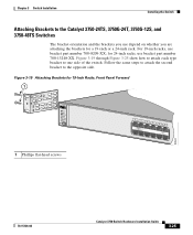
Follow the same steps to attach the second bracket to the Catalyst 3750-24TS, 3750G-24T, 3750G-12S, and 3750-48TS Switches The bracket orientation and the brackets you use depend on whether you are attaching the brackets for a 19-inch or a 24-inch rack. ...MODE 1 Phillips flat-head screws 12 1X 34 56 78 9 10 11 12 11X 2X 12X 86560 78-15136-02 Catalyst 3750 Switch Hardware Installation Guide 3-25 Chapter 3 Switch Installation Installing the Switch Attaching Brackets to the opposite side. Figure 3-19 Attaching Brackets for 24-inch racks, use bracket part number 700-8209-...
Follow the same steps to attach the second bracket to the Catalyst 3750-24TS, 3750G-24T, 3750G-12S, and 3750-48TS Switches The bracket orientation and the brackets you use depend on whether you are attaching the brackets for a 19-inch or a 24-inch rack. ...MODE 1 Phillips flat-head screws 12 1X 34 56 78 9 10 11 12 11X 2X 12X 86560 78-15136-02 Catalyst 3750 Switch Hardware Installation Guide 3-25 Chapter 3 Switch Installation Installing the Switch Attaching Brackets to the opposite side. Figure 3-19 Attaching Brackets for 24-inch racks, use bracket part number 700-8209-...

Hardware Installation Guide
Page 87
86563 Chapter 3 Switch Installation Figure 3-22 Attaching Brackets for 24-Inch Racks, Rear Panel Forward Installing the Switch 1.6A-100R>09A-A2T0,IN05GV0-~60 HZ [email protected] 1 1 Phillips flat-head screws Figure 3-23 Attaching Brackets for 19-Inch Telco Racks to Catalyst 3750-24TS, 3750G-24T, and 3750-48TS Switches 9 10 11 12 11X 12X 13 14 13X 15 16 17 18 19 20 21 22 23 24 23X 14X 24X Catalyst 3750 SERIES 1 2 1 1 Phillips flat-head screws 86564 78-15136-02 Catalyst 3750 Switch Hardware Installation Guide 3-27
86563 Chapter 3 Switch Installation Figure 3-22 Attaching Brackets for 24-Inch Racks, Rear Panel Forward Installing the Switch 1.6A-100R>09A-A2T0,IN05GV0-~60 HZ [email protected] 1 1 Phillips flat-head screws Figure 3-23 Attaching Brackets for 19-Inch Telco Racks to Catalyst 3750-24TS, 3750G-24T, and 3750-48TS Switches 9 10 11 12 11X 12X 13 14 13X 15 16 17 18 19 20 21 22 23 24 23X 14X 24X Catalyst 3750 SERIES 1 2 1 1 Phillips flat-head screws 86564 78-15136-02 Catalyst 3750 Switch Hardware Installation Guide 3-27